1
Rev 1/04 - 03
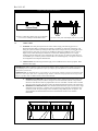
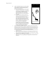
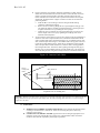
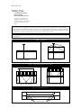
Figure 6 – Plate Shoe
iv.
v.
Attach, as illustrated in figure 2a, the 3 side steadying
cables. Install the 3 side steadying cables on back
(opposite side from the HLL) and two sides of each
safety pole section (Section 2).
1. First attach the appropriate plate shoes for either
2x4 (Section 7), 2x6 (Section 8), or 3x4 (Section
9) to the exterior wall sil-plates. Secure the plate
shoes through the pre-drilled holes using 6
standard 10d common nails, as illustrated in
figure 6. Make sure they are securely attached to
the sil-plate.
2. Locate and attach the tensioning cables (Part
Number 10) to the D-ring located on the section
of the safety pole directly below the top tee
section of the safety pole (Section 4). Attach the
other end of the tensioning cables to the Plate
Shoes. String together tensioning cables, if more
than one tensioning cable is required to reach the
plate shoe. Tighten the tensioning cable to
provide steady tension by tightening the
Exterior wall sil-plate
tensioning cable winch. Repeat this process for
the other tensioning cables. If you are installing a
HLL, do not tighten the back tensioning cable at
this point. The tensioning cables should not
exceed a 45 degree angle above the floor.
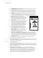
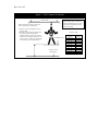
Figure 2.0 illustrates a typical HLL Safety Pole installation. The HLL and end anchors
must be located above the users at all times to reduce the loads on the end anchors. The
Self retracting Lifeline, when fully retracted, must be above the harness attachment level.
The HLL must be positioned to minimize the swing fall and free fall. The fall clearance
in figure 7 must also be taken into account when positioning the HLL.
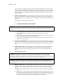
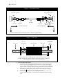
1. Install the HLL to the anchorage connectors using the double locking carabineers as
illustrated in figure 8.
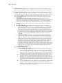
2. Remove the excess slack by pulling the wire rope through the cable grip. The jaw
release bolt must be extended, as illustrated in figure 9, allowing the jaws to tighten
around the wire rope, holding the wire rope tight.
3. Tighten the wire rope until the sag at the system mid span is 6 inches or less, with no
weight on the wire rope, by tightening the steadying cable on the backside of the
Safety Poles.