1
c) In channel entry mode (with channel number flashing in top
or bottom readout), press briefly to increment channel
number. Pressing the button briefly with the display showing
CH-9 resets readout to CH-0
11. Two-function Hold/CH button:
a) Press briefly to hold (freeze) reading(s). Press briefly again to
release hold.
b) Press and hold for >3 seconds to enter Hi channel entry
mode. In Hi channel entry mode, press briefly to enter Lo
channel entry mode. In both modes, if no entry is made within
10 seconds, readout(s) revert to showing real-time
measurements.
12. Rotary dial
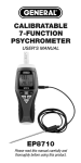
13. COM jack for black (negative) test lead
14. Jack for red (positive) test lead
15. Battery compartment (on back of unit)
16. Black (negative) test lead
17. Red (positive) test lead. Contains fast-acting ceramic fuse rated
at 500mA/500V
18. Protective caps for test leads
The table below explains the symbols and abbreviations used on the
meter and in this manual.
Electrical Symbols Used On the Meter and In This Manual
Adjust reading to zero
Tx (where X = 0-9) Wireless transmit mode
Rx (where X = 0-9) Wireless receive mode
HOLD
10
Alternating voltage / current
Direct voltage / current
Negative
Freeze / Hold reading