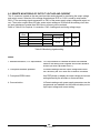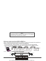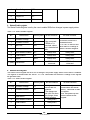
1
GE TECHNICAL MANUAL FOR KW Progra NESYSTM 10KW/15 pplies mmable DC Power Su Document: 83-530-000 Rev G TDK-Lambda Americas Inc. High Power Division 405 Essex Road, Neptune, NJ 07753 Tel: (732) 922-9300 Fax: (732) 922-9334 WARRANTY This TDK-Lambda Americas Inc. product is warranted against defects in materials and workmanship for a period of five years from date of shipment. During the warranty period, TDK-Lambda Americas Inc. will, at it’s option, either repair or replace products which prove to be defective. LIMITATION OF WARRANTY The warranty shall not apply to defects resulting from improper or inadequate usage or maintenance by the buyer, buyer supplied products or interfacing. The warranty shall not apply to defects resulting from unauthorized modifications, or from operation exceeding the environmental specifications of the product, or if the QA seal has been removed or altered by anyone other than TDK-Lambda Americas Inc. authorized personnel. TDK-Lambda Americas Inc. does not warrant the buyer’s circuitry or malfunctions of TDK-Lambda Americas Inc. products resulting from the buyer’s circuitry. Furthermore, TDK-Lambda Americas Inc. does not warrant any damage occurring as a result of the buyer’s circuitry or the buyer’s - supplied products. THIS LIMITED WARRANTY IS IN LIEU OF, AND TDK-LAMBDA AMERICAS INC DISCLAIMS AND EXCLUDES, ALL OTHER WARRANTIES, STATUTORY, EXPRESS OR IMPLIED, INCLUDING, WITHOUT LIMITATION, ANY WARRANTY OF MERCHANTABILITY OR FITNESS FOR A PARTICULAR PURPOSE, OR OF CONFORMITY TO MODELS OR SAMPLES. WARRANTY SERVICE This product must be returned to an authorized TDK-Lambda Americas Inc. service facility for repairs or other warranty service. For products returned to TDK-Lambda Americas Inc. for warranty service, the buyer shall prepay shipping charges to TDK-Lambda Americas Inc. If the unit is covered under the foregoing warranty then TDK-Lambda Americas Inc. shall pay the shipping charges to return the product to the buyer. Refer to Section 3.11 for repackaging for shipment. DISCLAIMER The information contained in this document is subject to change without notice. TDK-Lambda Americas Inc. shall not be liable for errors contained in this document or for incidental or consequential damages in connection with the furnishing, performance or use of this material. No part of this document may be photocopied, reproduced or translated into another language without the prior written consent of TDKLambda Americas Inc. TRADEMARK INFORMATION Genesys™ power supply is a trademark of TDK-Lambda Americas Inc. Microsoft™ and Windows™ are trademarks of Microsoft Corporation. THE FCC WANTS YOU TO KNOW This equipment has been tested and found to comply with the limits for a Class A digital device, pursuant to Part 15 of the FCC rules. These limits are designed to provide reasonable protection against harmful interference when the equipment is operated in a commercial environment. This equipment generates, uses and can radiate radio frequency energy and, if not installed and used in accordance with the instructions, may cause harmful interference to radio communications. Operation of this equipment in a residential area is likely to cause harmful interference, in which case the user will be required to correct the interference at his own expense. FCC WARNING Modifications not expressly approved by manufacturer could void the user authority to operate the equipment under FCC Rules. 1 83-000-016 Rev. F SAFETY INSTRUCTIONS CAUTION The following safety precaution must be observed during all phases of operation, service and repair of this equipment. Failure to comply with the safety precautions or warnings in this document violates safety standards of design, manufacture and intended use of this equipment and may impair the builtin protections within. TDK-Lambda Americas Inc. shall not be liable for user’s failure to comply with these requirements. INSTALLATION CATEGORY TM The Genesys power supply series has been evaluated to INSTALLATION CATEGORY II. Installation category (over voltage category) II: local level, appliances, portable equipment etc. With smaller transient over voltage than Installation Category (over voltage category) III. GROUNDING This product is a Safety Class 1 instrument. To minimize shock hazard, the instrument chassis must be connected to an electrical ground. The instrument must be connected to the AC power supply mains through a three conductor power cable, with the ground wire firmly connected to an electrical ground (safety ground) at the power outlet. For instruments designed to be hard-wired to the supply mains, the protective earth terminal must be connected to the safety electrical ground before another connection is made. Any interruption of the protective ground conductor or disconnection of the protective earth terminal will cause a potential shock hazard that might cause personal injury. WARNING OUTPUT TERMINALS GROUNDING There is a potential shock hazard at the RS232-485 and the IEEE ports when using power supplies with rated or combined voltage greater than 400V and the Positive Output of the Power Supply is grounded. Do Not connect the Positive Output to ground when using the RS232/485 or IEEE. FUSES Fuses must be changed by authorized TDK-Lambda Americas Inc. service personnel only. For continued protection against risk of fire, replace only with the same type and rating of fuse. INPUT RATINGS Do not use AC supply, which exceeds the input voltage and frequency rating of this instrument. The TM input voltage and frequency rating of the Genesys power supply series has three input ranges depending on the model type ordered. Ranges are 180-253 Vac/360-440 Vac/432-528 Vac, 50-60Hz. For safety reasons, the mains supply voltage fluctuations should not exceed above voltage range. LIVE CIRCUITS Operating personnel must not remove the instrument cover. No internal adjustment or component replacement is allowed by non-TDK-Lambda Americas Inc. qualified personnel. Never replace components with power cable connected. To avoid injuries, always disconnect power, discharge circuits and remove external voltage source before touching components. PARTS SUBSTITUTIONS & MODIFICATIONS Parts substitutions and modifications are allowed by authorized TDK-Lambda Americas Inc. service personnel only. For repairs or modifications, the instrument must be returned to an authorized TDKLambda Americas Inc. service facility. 2 83-530-000 Rev G SAFETY INSTRUCTIONS ENVIRONMENTAL CONDITIONS The Genesys TM power supply series safety approval applies to the following operating conditions: *Indoor use *Maximum relative humidity: 80% (no condensation) *Pollution degree 2 *Ambient temperature: 0°C to 50°C *Altitude: up to 3000m ATTENTION Observe Precautions for handling Electrostatic Sensitive Devices. CAUTION Risk of Electrical Shock Instruction manual symbol. The instrument will be marked with this symbol when it is necessary for the user to refer to the instruction manual. Indicates hazardous voltage. Indicates ground terminal. Protective Ground Conductor Terminal must be connected to Earth Ground. Off (Supply) On (Supply) The WARNING sign denotes a hazard. An attention to a procedure is called. Not following procedure correctly could result in personal injury. A WARNING sign should not be skipped and all indicated conditions must be fully understood and met. The CAUTION sign denotes a hazard. An attention to a procedure is called. Not following procedure correctly could result in damage to the equipment. Do not proceed beyond a CAUTION sign until all indicated conditions are fully understood and met. FCC COMPLIANCE NOTICE: Note: This equipment has been tested and found to comply with the limits for a Class A digital device, pursuant to part 15 of the FCC Rules. These limits are designed to provide reasonable protection against harmful interference when the equipment is operated in a commercial environment. This equipment generates uses, and can radiate radio frequency energy and, if not installed and used in accordance with the instruction manual, may cause harmful interference to radio communications. Operation of this equipment in a residential area is likely to cause harmful interference in which case the user will be required to correct the interference at his own expense. 3 83-530-000 Rev. G WARRANTY .............................................................................................................................. 1 CHAPTER 1 GENERAL INFORMATION................................................................................... 6 1.1 USER MANUAL CONTENT ...................................................................................................................6 1.2 INTRODUCTION .....................................................................................................................................6 1.3 ACCESSORIES......................................................................................................................................8 1.4 MODEL NUMBER FORMAT ...................................................................................................................9 CHAPTER 2 SPECIFICATIONS .............................................................................................10 CHAPTER 3 INSTALLATION ................................................................................................14 3.1 GENERAL 14 3.2 PREPARATION FOR USE....................................................................................................................14 3.3 INITIAL INSPECTIONS .........................................................................................................................14 3.4 RACK MOUNTING ...............................................................................................................................14 3.5 LOCATON, MOUNTING AND COOLING .............................................................................................15 3.6 AC SOURCE REQUIREMENTS ...........................................................................................................15 3.7 AC INPUT POWER CONNECTION......................................................................................................15 3.8 TURN-ON CHECKOUT PROCEDURE.................................................................................................17 3.9 CONNECTING THE LOAD ............................................................................................................19 3.10 LOCAL AND REMOTE SENSING.......................................................................................................22 CHAPTER 4 FRONT AND REAR PANEL CONTROLS AND CONNECTORS .......................25 4.1 INTRODUCTION ...................................................................................................................................25 4.2 FRONT PANEL CONTROLS AND INDICATORS ................................................................................25 4.3 REAR PANEL CONTROLS AND INDICATORS ...................................................................................29 4.4 REAR PANEL SW1 SETUP SWITCH ..................................................................................................29 4.5 REAR PANEL J1 PROGRAMMING AND MONITORING CONNECTOR.............................................31 CHAPTER 5 LOCAL OPERATION ...........................................................................................33 5.1 INTRODUCTION ...................................................................................................................................33 5.2 STANDARD OPERATION.....................................................................................................................33 5.3 OVER VOLTAGE PROTECTION (OVP)...............................................................................................34 5.4 UNDER VOLTAGE LIMIT (UVL) ...........................................................................................................35 5.5 FOLDBACK PROTECTION...................................................................................................................35 5.6 OUTPUT ON/OFF CONTROL ..............................................................................................................35 5.7 OUTPUT SHUT-OFF (SO) CONTROL VIA REAR PANEL J1 CONNECTOR .....................................35 5.8 ENABLE/DISABLE CONTROL VIA REAR PANEL J1 CONNECTOR .................................................36 5.9 CV/CC SIGNAL .....................................................................................................................................36 5.10 PS_OK SIGNAL...................................................................................................................................36 5.11 SAFE START AND AUTO-RESTART MODES ..................................................................................37 5.12 OVER TEMPERATURE PROTECTON (OTP)....................................................................................37 5.13 LAST SETTING MEMORY..................................................................................................................37 5.14 SERIES OPERATION .........................................................................................................................37 5.15 PARALLEL OPERATION ....................................................................................................................40 5.16 DAISY-CHAIN CONNECTION ............................................................................................................41 5.17 ADVANCED PARALLEL OPERATION ...............................................................................................41 5.18 FRONT PANEL LOCKING ..................................................................................................................44 CHAPTER 6 REMOTE ANALOG PROGRAMMING ................................................................45 6.1 INTRODUCTION ...................................................................................................................................45 6.2 LOCAL/REMOTE ANALOG INDICATION ............................................................................................45 6.3 LOCAL/REMOTE ANALOG INDICATION ............................................................................................45 6.4 REMOTE VOLTAGE PROGRAMMING OF OUTPUT VOLTAGE AND CURRENT LIMIT ..................46 6.5 RESISTIVE PROGRAMMING OF OUTPUT VOLTAGE AND CURRENT LIMIT .................................47 6.6 REMOTE MONITORING OF OUTPUT VOLTAGE AND CURRENT ..................................................48 4 83-530-000 Rev G CHAPTER 7 RS232 & RS485 REMOTE CONTROL ..............................................................49 7.1 INTRODUCTION ..................................................................................................................................49 7.2 CONFIGURATION ...............................................................................................................................49 7.3 REAR PANEL RS232/485 CONNECTOR............................................................................................50 7.4 CONNECTING POWER SUPPLIES TO RS232 BUS...........................................................................51 7.5 COMMUNICATION INTERFACE PROTOCOL....................................................................................52 7.6 ERROR MESSAGES............................................................................................................................53 7.7 COMMAND SET DESCRIPTION .........................................................................................................54 7.8 GLOBAL OUTPUT COMMANDS .........................................................................................................56 7.9 SINGLE BYTE COMMANDS................................................................................................................57 7.10 STATUS, ERROR AND SRQ REGISTERS ........................................................................................62 7.11 SERIAL COMMUNICATION TEST SET-UP .......................................................................................65 CHAPTER 8 ISOLATED ANALOG PROGRAMMING OPTION..............................................67 8.1 INTRODUCTION ...................................................................................................................................67 8.2 SPECIFICATIONS.................................................................................................................................67 8.3 ISOLATED PROGRAMMING & MONITORING CONNECTOR ...........................................................68 8.4 SETUP AND OPERATING INSTRUCTIONS........................................................................................69 CHAPTER 9 MAINTENANCE .................................................................................................70 9.1 INTRODUCTION ...................................................................................................................................70 9.2 UNITS UNDER WARRANTY ................................................................................................................70 9.4 ADJUSTMENTS AND CALIBRATION ..................................................................................................70 9.5 PARTS REPLACEMENT AND REPAIRS .............................................................................................70 9.6 TROUBLESHOOTING ..........................................................................................................................70 5 83-530-000 Rev. G CHAPTER 1 GENERAL INFORMATION 1.1 USER MANUAL CONTENT This User’s Manual contains the operating instructions, installation instructions and specifications of the TM Genesys 15KW and 10KW power supply series. The instructions refer to the standard power supplies, including the built-in RS232/485 serial communication. For information related to operation with the optional IEEE programming, refer to User’s Manual for Power Supply IEEE/IEMD Programming Interface. For information related to operation with the optional LAN programming, refer to the User’s Manual for Power Supply LAN Programming Interface. 1.2 INTRODUCTION 1.2.1 General Description TM Genesys power supplies are wide output range, high performance switching power supplies. The TM Genesys series is power factor corrected and operates from specified AC voltage range continuously. Output voltage and current are continuously displayed and LED indicators show the complete operating status of the power supply. The Front panel controls allow the user to set the output parameters, the protections levels (Over-Voltage protection, Under-Voltage limit and Foldback) and preview the settings. The rear panel includes the necessary connectors to control and monitor the power supply operation by remote analog signals or by the built-in serial communication (RS232/485). GPIB programming and Isolated-Analog programming/monitoring are optional 1.2.2 Features and options Constant Voltage / Constant Current with automatic crossover. Embedded Microprocessor Controller. Built-in RS-232/RS-485 Interface. Voltage & Current high resolution adjustment by digital encoders. High accuracy programming/readback. Last Setting Memory. Independent Remote ON/OFF (opto-isolated) and remote Enable/Disable. Remote sensing to compensate for voltage drop of power leads. External Analog Programming and Monitoring standard (0-5V or 0-10V, user selectable). Zero stacking-no ventilation required at the top and bottom surface of the power supply. Optional GPIB interface (SCPI compatible). Optional Isolated Analog programming/monitoring (0-5V or 0-10V, user selectable and 4-20mA). 6 83-530-000 Rev G 1.2.3 Control via the serial communication port The following parameters can be programmed via the serial communication port: 1. Output voltage setting. 2. Output current setting. 3. Output voltage measurement. 4. Output On/Off control. 5. Output current measurement. 6. Foldback protection setting 7. Over-voltage protection setting and readback. 8. Under-Voltage limit setting and readback. 9. Power-supply start up mode (last setting or safe mode). 1.2.4 Analog voltage programming and monitoring Analog inputs and outputs are provided at the rear panel for analog control of the power supply. The output voltage and the current limit can be programmed by analog voltage or by resistor, and can be monitored by analog voltage. The power supply output can be remotely set to On or Off and analog signals monitor the proper operation of the power supply and the mode of operation (CV/CC). 1.2.5 Parallel operation TM Genesys power supplies of the same output voltage and current rating can be paralleled in masterslave configuration with automatic current sharing to increase power available. 1.2.6 Output connections Output connections are made to rear panel via bus-bars up to 300V. For greater than 300Vo via stud terminals. Either the positive or negative terminal may be grounded or the output may be floated. Contact factory for assistance with higher float voltage applications. Local or remote sense may be used. In remote sense, the voltage drop on the load wires should be minimized. Refer to the specifications for the maximum voltage drop value. 1.2.7 Cooling and mechanical construction TM The Genesys series is cooled by internal fans. At the installation, care must be taken to allow free airflow into the power supply via the front panel and out of the power supply via the rear panel. CAUTION Observe all torque guidelines within this manual. Over torqueing may damage unit or accessories. Such damage is not covered under manufacturer’s warranty. 7 83-530-000 Rev. G 1.3 ACCESSORIES 1.3.1 Included Accessories - The following accessories are delivered with the power supply. 1.3.1.1 Serial Link Cable: Serial linking cable linking power supplies by RS-485 communication.(GEN/RJ45). Cable description: 0.5m Length, shielded, RJ-45 type plugs, eight (8) contacts (P/N 15-507-201) 1.3.1.2 Hardware: Strain Relief for AC Cord Output terminal Shield DB25 Programming Plug kit (AMP 749809-9) 1.3.2 Optional Communication Cables RS-232 Cables to connect GEN to Serial Port on PC GEN to PC (DB9) GEN 232/9 P/N 15-507-203 GEN to PC (DB25) GEN 232/25 P/N 15-507-204 RS-485 Cable to connect GEN to Serial Port on PC GEN to PC(DB9) GEN/485-9 P/N 15-507-202 1.3.3 AC cables – Not applicable. 8 83-530-000 Rev G 1.4 MODEL NUMBER FORMAT TM The model numbering system for Genesys power supply includes symbols for features and options. They are separated by dashes. The following chart explains the model number for the GEN Power Supply Family. * Factory Installed. Limit one (1) per Power Supply. Note 1: See Specifications for Input Range. Note 2: CE Mark with IEMD to 400VDC Output, without IEMD to 600VDC Note 3: All 3 are four wire input = 3 + GND (No Neutral). Note 4: Analog Meters are NOT available. Note 5: IS510, IS420, IEMD, or LAN may not be installed together. EXAMPLES: GEN10-1000-3P208 GEN10-1000-IEMD-3P400 WARNING IEEE 488/RS232 OPTION There is a potential shock hazard at the RS232-485 and the IEEE ports when using power supplies with rated or combined voltage greater than 400V and the Positive Output of the Power Supply is grounded. Do Not connect the Positive Output to ground when using the RS232/485 or IEEE. 9 83-530-000 Rev. G CHAPTER 2 SPECIFICATIONS All specifications are subject to change without notice. Contact factory for specific model availability. 1.Rated output voltage 2.Rated Output Current 3.Rated output power 1. OUTPUT RATING (Duty Cycle Continuous Duty). 1.1 STANDARD MODELS - 10kW V 7.5 10 12.5 20 25 30 40 A 1000 1000 800 500 400 333 250 kW 7.5 10.0 10.0 10.0 10.0 10.0 10.0 1.Rated output voltage 2.Rated Output Current 3.Rated output power 1.1 STANDARD MODELS - 15kW V N/A N/A N/A N/A A kW 1. Input voltage/freq.(range) 2.No of phase 3. Dropout voltage 4. Input current 180/360/432Vac 5. Power Factor 6. Efficiency at Low Line,100% load 7. Inrush current 8. Leakage current 9. Input Protection 10. Fuse 11. Input Overvoltage Protection 12. Phase Imbalance N/A N/A N/A 50 200 10.0 60 167 10.0 80 125 10.0 100 100 10.0 125 80 10.0 150 66 9.9 200 50 10.0 250 40 10.0 300 33 9.9 400 25 10.0 500 20 10.0 600 17 10.2 N/A 60 80 250 187.5 15.0 15.0 100 150 15.0 125 120 15.0 150 100 15.0 200 75 15.0 250 60 15.0 300 50 15.0 400 37.5 15.0 500 30 15.0 600 25 15.0 200 250 300 400 500 600 400 500 600 200 60 10 10 300 60 8 10 350 60 7 10 5 5 5 400 500 600 2.INPUT CHARACTERISTICS V 7.5 10 12.5 20 25 30 40 50 60 80 100 125 150 --- 208VAC (180-253); 400VAC (360-440); 480VAC (432-528), all 47-63Hz. --- 3 Phase (Wye or Delta) 4 wire total (3 Phase and 1 protective earth ground) V 175/355/425 A 10kw - 45/23/20 15kW - 64/32/27 All at full rated output power. --- 0.88 Passive % 77min for 7.5KW, 83 min for 10kW; 88 min for 15kW A Not to exceed full rated Input current See Para. 2.4 mA 3.5 (EN60950-1) max. --- 208 Circuit Breaker, 400/480 - Line Fuse --- 400/480 Input Only % Unit shall not be damaged by line overvoltage with max. duration of 100uSec. Up to 120% of nominal AC input voltage. = < 5% on Three Phase Input 3. STATIC CHARACTERISTICS V 7.5 10 12.5 20 25 30 40 50 60 80 100 125 150 200 250 300 0.01% of FS from lo min. to lo max 1. Max. line regulation c.v --- 0.1% of FS from Io min. to Io max 0.05% of FS from lo min. to lo max 2. Max. line regulation c.c --- 0.1% of FS from Vo min. to Vo max 0.02% of FS lo min. to lo max 3. Max load regulation c.v --- 0.1% of FS from Io min. to Io max 0.75% of FS from Vo min. to Vo max 4. Max load regulation c.c --- 0.1% of FS from Vo min. to Vo max 5. Temp. drift c.v --- +/-0.05% of Full Scale Over 8 hours, after 30 minute warm up, constant Line, Load & Temperature 6. Temp. drift c.c --- +/-0.05% of Full Scale Over 8 hours, after 30 minute warm up, constant Line, Load & Temperature 7. Stability c.v PPM/C 200 (0.02% Full Scale)/Degree C PPM/C 300( 0.03% Full Scale)/ Degree C 8. Stability c.c 9. Output noise p-p(20MHz) c.v mV 60 60 60 60 60 60 60 75 75 100 100 125 135 135 200 200 10. Ripple r.m.s 5Hz~1MHz c.v mV 20 20 20 20 20 20 20 20 20 25 25 25 25 35 35 60 11. Ripple r.m.s 5Hz~1MHz c.c (10kW) mA 5100 5100 2600 2600 1700 1700 100 80 67 50 40 32 20 20 16 13 12. Ripple r.m.s. 5Hz~1MHz c.c (15kW) mA – – – – – – – – 100 100 100 50 50 20 20 20 *Ripple and Noise at Full Rated Voltage & Load at 25C, Nominal Line. For models not listed use the ripple limit of the next higher voltage model. Per EIJ RC9002A 13. Rem. sense compensation/wire V 1 1 1 1 1 1.5 2 3 3 4 5 5 5 5 5 5 1. OCP 2. OCP type 3. Knee point protection 4. Short circuit protection 5. Short circuit burn-in 6. Foldback protection 7. Foldback response time 8. OVP type 9. OVP programming accuracy 10. OVP adjustment method 11. OVP trip point 12. OVP response time 13. Max. OVP reset time 14. Output under voltage limit 15. Input under voltage protection 16. Over temp. protection 17. Phase Loss Protection 4.PROTECTIVE FUNCTIONS V 7.5 10 12.5 20 25 30 40 50 60 80 100 125 150 200 250 % 0~100 --- Constant current --- None. No damage at knee point operation --- Yes --- Yes --- Output shut down , manual reset by front panel OUT button. S Less than 1 --- Inverter shut-down, manual reset by On/Off recycle or by OUT button % 5% Full Scale --- Adjust by front panel Voltage encoder and comm port. 0.05 to (1.02-1.05) x Rated Output Voltage V mS Less than 10mS for Output to begin to drop. S 7 from Turn On. --- Preset by front panel or communication port. Prevents from adjusting Vout below limit. Raises the Output good signal in case of output voltage is below limit. --- Yes. Power supply shut down below low line. --- Unit shall shut down when internal temperature exceeds safe operating levels. (Latched in Safe mode and unlatched in auto mode). Yes 10 83-530-000 Rev G 300 5. DYNAMIC CHARACTERISTICS V 7.5 10 12.5 20 400 500 600 100 100 100 100 100 100 100 100 100 100 100 100 100 100 100 100 100 100 100 100 100 100 100 100 100 100 100 100 100 100 100 100 100 100 Time for the output voltage to recover within 2% of its rated output voltage for a load change of 50~100% or 100~50% of rated output set-point: less than 3. Note: Properties 5.1-5.6 with Resistive Load. S 2 maximum from enable output until output stable. --- Overshoot limited to 125% Rated Output. Voltage at No-Load, Full-Load, Resistive load. S Less than 7 (without IEEE option) 100 100 100 100 1. Up-prog. response time, 0~Vomax fullload 2. Down-prog response time full-load 3. Transient response time (cv mode) 4. Time for Ouput Stable 5. Output fall and rise 6.Start-up delay 1. Vout voltage programming 2. Iout voltage programming 3. Vout resistor programming 4. Iout resistor programming 5. On/Off control (rear panel) 6. Output current monitor 7. Output voltage monitor 8. Power supply OK signal 9. Parallel operation 10. Series operation 11. CV/CC signal 12. Enable/Disable 13. Remote/Local selection 14. Remote/Local signal 1. Control functions 2. Display 3. Indications 25 30 40 50 60 80 100 125 150 200 250 300 mS mS mS 6. REMOTE ANALOG CONTROL AND SIGNALS --- 0~100%, 0~5V or 0~10V, user selectable. Accuracy & Linearity +/-1% of Rated Vo. --- 0~100%, 0~5V or 0~10V, user selectable. Accuracy & Linearity +/-1% of Rated Io. --- 0~100%, 0~5/10kohm full scale, user selectable. Accuracy & Linearity +/-1% of Rated Vo. --- 0~100%, 0~5/10kohm full scale, user selectable. Accuracy & Linearity +/-1% of Rated Io. --- By Voltage: 0.6V = Disable, 2-15V = enable (default) or dry contact, user selectable logic --- 0~5V or 0~10V , accuracy:1% , user selectable --- 0~5V or 0~10V , accuracy:1% , user selectable --- Yes. TTL high-OK, 0V (500ohm impedance)-Fail --- Up to Four (4) identical units may be connected in Master/Slave Mode with 'Single' wire connection. In Advanced parallel feature, the current of Master Unit, multiplied by number of units connected in parallel, is made available on digital interface and displayed on front panel of Master unit. Remote analog current monitor of the Master is scaled to output current of the Master unit (only). --- Possible (with external diodes) , up to identical 2 units with total output not to exceed +/-600V from chassis ground. --- CV: TTL high (4~5V) source: 10mA, CC: TTL low (0~04V):10mA --- Dry contact. Open:off , Short: on. Max. voltage at Enable/Disable Contacts 6V --- Selects Remote or Local operation by elect. Voltage: 0~0.6V/2~15V, <0.6V = Local 2-15V = Remote --- Signals operating mode in use. 7.FRONT PANEL --- Vout/ Iout manual adjust by separate encoders --- OVP/UVL manual adjust by Volt. Adjust encoder --- Address selection by Voltage adjust encoder. No of addresses:31 --- Go to Local --- Output On/Off --- AC On/Off --- Foldback control (CV to CC) --- RS232/485 and IEEE488.2 selection by IEEE or LAN enable switch and DIP switch --- Baud rate selection by Current adjust encoder. --- Re-start modes (auto , safe) --- Front Panel Lock/Unlock --- Parallel Master Slave: H1 = One Master, Zero Slave, H2 One Master, One Slave H3 = One Master, Two Slaves H4 = One Master, Three Slaves, S = Slave --- Vout: 4 digits , accuracy: 0.5% of rated Vout+/-1count , Green LED's , Size:10mm --- Iout: 4 digits , accuracy: 0.5% of rated Iout+/-1count , Green LED's , Size:10mm Voltmeter is user selectable to read either local voltage (at power supply) or remote voltage (at the load). --- ADDR., OVP/UVL , V/A , FOLD, REM./LOCAL, OUT ON/OFF, LFP/UFP, IEEE, LAN, Hx (Parallel Master) or S (Slave). CC/CV : GREEN LED's. ALRM (OVP,OTP,FOLD,AC FAIL): RED LED 11 83-530-000 Rev. G 1. Functions: 2. Application software: 1. Vout programming accuracy 2. Iout programing accuracy 3. Vout programming resolution 4. Iout programming resolution 5. Vout readback accuracy 6. Iout readback accuracy 7. Vout readback resolution 8. Iout readback resolution OV Response time Other Functions 1. Cooling 2. Weight 3. Dimensions 4. Types of connectors 5.Front panel material & finish 6. Mounting method 7. Mounting positions 8. Output ground connection 9. Color and finish 10. Output Terminal covers 1. 2. 3. 4. 5. 6. Operating temp Start up temp. Storage temp Operating humidity Storage humidity Altitude 7. Vibration & Shock (208/400VAC) 8. Audible Noise 8. SOFTWARE SPEC. 1. Voltage/current setting 2. OVP/UVL setting 3. Actual voltage/current readback 4. Voltage/current setting readback 5. OVP/UVL setting readback 6. Output On/Off 7. Foldback protection setting 8. Status readback (cc/cv , ovp , otp , foldback, ac fault) 9. Model identification readback 10. Self test. 11. Calibration (not user access.) (DAC-Zero and max points , Display-Zero and max) 12. Last setting recall (at power off). 13. Re-start mode setting 14. Front Panel Lock/Unlock 1.Drivers to LabView and LabWindows 2. Simple operating program 9. DIGITAL PROGRAMMING AND READBACK --+/-0.5% of rated output voltage --+/-0.5% of rated output current for units with Io <187.5 +/-0.7% of rated output current for Io <187.5 --- 0.02% of full scale (To be confirmed) --- 0.04% of full scale (To be confirmed) --- 0.1%+0.2% of rated output voltage Accuracy same as IEEE Programming Accuracy --- 0.1%+0.4% of rated output current Accuracy same as IEEE Programming Accuracy --- 0.02% of full scale --- 0.02% of full scale mS 20 mS maximum between output V exceeding IEEE limit and supply inhibit turning on. Set Over-Voltage Limit, Set Local/Remote Operating parameters and status available for display via host computer. 10. MECHANICAL CONSTRUCTION V 7.5 10 12.5 20 25 30 40 50 60 80 100 125 150 200 250 300 400 --- Fan driven, Airflow from Front to Rear. Supplemental vents on side that shall not be blocked. EIA Rack mounting, stackable. "Zero Stackable" top and bottom. Slides or suitable rear support required. Kg/Lb 43/97 --- H:3U ,W: 19" Rack, See 02-530-000 for outline drawing. --- 1) Input: Threaded Studs and terminal cover. Strain relief optional. 2) Output: Iout =>50A: bus-bars, Iout<37.5 a threaded stud terminal. 3) Analog programming: DB25, plastic connector, AMP, 747461-5, Female on Power Supply, Male on Mating connector 747321. Standard 25 pin D connector. 4) RS232/RS485, STD Phone Jack connector. 5) Isolated analog option: refer to Isolated Analog option spec. 08-030-200 6) IEMD Option, refer to IEMD Option Spec 08-030-100. --- RAL7035 Textured finish. --- Sandard 19" Rack Mount, provision for standard slides. Side/Rear Support is required; do not mount by F/P only. --- Horizontal. ---- M5 Stud --- Chassis Top/Sides/Bottom Yellow iridite. Front Panel RAL 7035 painted. --- Standard for all models with bus-bars. Closed connection for models with output connector. 500 600 11. ENVIRONMENTAL CONDITIONS C 0~50 C, 100% load. No operation > 50C C 0 C -20C to +70C % 20~80% RH Non-condensing % 10~90% RH Non-condensing --- Operating: 50º C up to 7500 ft., (2500m) 45º C from 7501 to 10,000ft (2501m - 3000m) Non Operating 40,000 ft (12,000m) G ASTM D4169, Standard Practice for Performance Testing of Shipping Containers and Systems, Shipping Unit: Single Package Assurance Level: Level II; Acceptance Criteria: Criterion 1 - No product damage Criterion 2 - Package is intact Distribution Cycle: Cy Air (intercity) and motor freight (local, single package up to 100 lbs.) (Note: for packages over 100 lbs, distribution cycle 12 - Air (intercity) and motor freight (local), unitized is used) db 65dBA at Full Load, measured 1m from Front Panel 12 83-530-000 Rev G 1. 208 Volts Input Models 1. ESD 2. Fast transients 3. Surge immunity 4. Conducted immunity 5. Radiated immunity 6. Power Frequency Magnetic Field 7. Conducted emission 8. Radiated emission 2. 400 Volts Input Models 1. ESD 2. Fast transients 3. Surge immunity 4. Conducted immunity 5. Radiated immunity 6. Power Frequency Magnetic Field 7. Voltage Dips, Short Interruptions and Voltage Variations Immunity Tests (400VAC Input Only) 8. Conducted emission 9. Radiated emission 1 . Elec trolytic ca pa citors life 2 . Grad e 4 . W a rranty 5 . She lf life 1 . ap plic able stan dards 2 . Insulation resistance J1 -1 J1 -2 J1 -3 J1 -4 J1 -5 J1 -6 J1 -7 J1 -8 J1 -9 J1 -1 0 J1 -1 1 J1 -1 2 J1 -1 3 J1 -1 4 J1 -1 5 J1 -1 6 J1 -1 7 J1 -1 8 J1 -1 9 J1 -2 0 J1 -2 1 J1 -2 2 J1 -2 3 J1 -2 4 J1 -2 5 12. EMC CE Mark --- EN61000-4-2 (IEC 801-2) Air-disch.+/-8kV , contact disch.+/-4kV --- EN61000-4-4 (IEC 1000-4-3) --- EN61000-4-5 (IEC 1000-4-5) --- EN61000-4-6 (IEC 1000-4-6) --- EN61000-4-3 (IEC 1000-4-3) EN61000-4-8 --- EN55011A, FCC part 15J-A --- EN55011A, FCC part 15J-A CE Mark --- EN61000-4-2 (IEC 801-2) Air-disch.+/-8kV , contact disch.+/-4kV --- EN61000-4-4 (IEC 1000-4-3) --- EN61000-4-5 (IEC 1000-4-5) --- EN61000-4-6 (IEC 1000-4-6) --- EN61000-4-3 (IEC 1000-4-3) --- EN61000-4-8 --- IEC 61000-4-11 ----- EN55011A, FCC part 15J-A EN55011A, FCC part 15J-A 13 . R ELIA BILITY SPEC S Yrs. More th an 3 yrs at 4 0C amb ient , 1 00% loa d --G-2 , La mbd a Grou p de rating crite ria & EIAJ RC R-91 02A co unt Re liabililty, G en eric FaIlure ra te s , 25 C Yrs. 5 yea rs Yrs. 5 yea rs , ele ctrolytic cap s s ha ll be refo rm ed after 2 yea rs 14 . SAFETY --UL /U LC 609 50 -1, EN6 095 0-1 re co gn iz ed . All O utpu ts are Ha za rd ous. (U nits with IE MD or ISO L op tion are Re co gnized u p to 4 00 volts o utput). C E Ma rk 208 & 40 0VAC in put on ly (CB Schem e). --100 Moh m at 5 00 Vd c 15 . J 1 Con nec tor EN A_ IN IF_ CO M IF_ CO M N/C N/C N/C N/C LOC /R EM VPG M IPGM VM ON CO M CV/CC EN A_ OU T SO PS_ OK N/C N/C N/C N/C LOC /R EM Signal VPG M_R TN IPGM _R TN IM ON P Ena ble/D is a ble D ry C onta ct with J1-1 4 Iso lated Interface C omm on . Re tu rn fo r SO, PS_ OK Iso lated Interface C omm on . Re tu rn fo r SO, PS_ OK Inpu t for se lectin g be tw ee n Loca l o r Re mo te a na lo g prog ram min g Inpu t for re mote an alo g vo lta ge/resistan ce program ming o f the O utpu t Voltag e Inpu t for re mote an alo g vo lta ge/resistan ce program ming o f the O utpu t C urre nt Ou tp ut Vo lta ge Mo nitor C ontrol Co mmo n for VMO N & IMO N Ou tp ut fo r C onstan t Voltag e/ C on sta nt C u rrent mod e ind ica tio n Ena ble/D is a ble D ry C onta ct with J1-1 Inpu t for Sh ut-O ff con trol of the ou tput. Ou tp ut fo r ind ica tio n of th e po we r supp ly status Ou tp ut R eturn R eturn Ou tp ut Ou tp ut fo r fo r fo r fo r fo r ind ica tin g if the u nit is in Lo ca l o r R emo te a na log prog ra mmin g mo de. VPGM J1-9; c on nected to N eg O utput IPGM J1-1 0; con ne cted to N eg O utpu t C urren t Mo nitor C urren t Bala nce in Parallel Op eration (O ne w ire - Re fe re nce to Ne ga tiv e Ou tp ut) 13 83-530-000 Rev. G CHAPTER 3 INSTALLATION 3.1 GENERAL This Chapter contains instructions for initial inspection, preparation for use and repackaging for shipTM ment. Connection to PC, setting the communication port and linking Genesys power supplies are described in Chapter 7. NOTE TM Genesys power supplies generate magnetic fields, which might affect the operation of other instruments. If your equipment is susceptible to magnetic fields, do not position it adjacent to the power supply. 3.2 PREPARATION FOR USE In order to be operational the power supply must be connected to an appropriate AC source. The AC source voltage should be within the power supply specification. Do not apply power before reading Section 3.6 and 3.7. Table 3-1 below, describes the basic setup procedure. Follow the instructions in Table 3-1 in the sequence given to prepare the power supply for use. Step no. Item Description Reference 1 Inspection Initial physical inspection of the power supply Section 3.3 2 Installation Section 3.4 Section 3.5 3 AC source Installing the power supply, Ensuring adequate ventilation. AC source requirements Connecting the power supply to the AC source 4 Test Turn-on checkout procedure. Section 3.8 5 Load connection Wire size selection. Local/Remote sensing. Single or multiple loads. Section 3.9 6 Default setting The power supply setting at shipment. Section 7.2.4 4.4.1, 3.9.4 Section 3.6 Section 3.7 Table 3-1: Basic setup procedure 3.3 INITIAL INSPECTIONS Prior to shipment this power supply was inspected and found free of mechanical or electrical defects. Upon unpacking of the power supply, inspect for any damage, which may have occurred in transit. The inspection should confirm that there is no exterior damage to the power supply such as broken knobs or connectors and that the front panel and meters face are not scratched or cracked. Keep all packing material until the inspection has been completed. If damage is detected, file a claim with carrier immediately and notify the TDK-Lambda Americas Inc. sales or authorized service facility nearest you. 3.4 RACK MOUNTING The Genesys TM power supply series is designed to fit in a standard 19” equipment rack. 3.4.1 To install the Power Supply in a rack: 1. Use the front panel rack-mount brackets to install the power supply in the rack. 14 83-530-000 Rev G 2. Use a support bar to provide adequate support for the rear of the power supply. Do not obstruct the air exhaust at the rear panel of the unit. 3.5 LOCATON, MOUNTING AND COOLING This power supply is fan cooled. The air intake is at the front panel and the exhaust is at the rear panel. Upon installation allow cooling air to reach the front panel ventilation inlets. Unrestricted air space at the front and the rear of the unit is necessary for proper cooling of power supply. 3.6 AC SOURCE REQUIREMENTS TM The Genesys series can be operated from a nominal 208V, 400V or 480V three phase, 4 wire, 4763 Hz. The input voltage range and current required for each model is specified in Chapter 2. Ensure that under heavy load, the AC voltage supplied to the power supply does not fall below the specifications described in Chapter 2. 3.7 AC INPUT POWER CONNECTION CAUTION Connection of this power supply to an AC power source should be made by an electrician or other qualified personnel. Do not exceed the torque specified on input stud terminals. WARNING There is a potential shock hazard if the power supply chassis (with cover in place) is not connected to an electrical safety ground via the safety ground in the AC input stud terminals. WARNING Some components inside the power supply are at AC/DC voltage even when the On/Off switch is in the “Off” position. To avoid electric shock hazard, disconnect the line and load and wait 15 minutes before removing cover. The customers AC line connects to the power supply through four stud type terminals. Only use a power cable with the correct voltage and current ratings. The recommended wire gauge is listed in the table in section 3.7.1. The ground wire must be equal to or larger than the recommended gauge for phase. The power supply must be permanently connected to an approved AC distribution box with suitably rated overcurrent protection (60Amp UL Listed fuse for 208V input, and 40 Amp UL listed fuse for 400/480 input). 15 83-530-000 Rev. G Input Rating Label Input Terminal Block Input Terminal Block with cover. NOTE: The figure shows input connection from left side. For connection from right side reverse the input cover. Figure 3.1 3.7.1 Recommended Cable Size for Input Connection INPUT VOLTAGE CURRENT RMS AMPS PER PHASE RECOMMENDED COPPER WIRE SIZE 208 75 4 AWG 400 45 6 AWG 480 35 7 AWG The AC input current and voltage rating is marked on the rear terminal of the power supply. The Protective Earth Ground must be connected before applying AC Line Power to the power supply. 16 83-530-000 Rev G 3.8 TURN-ON CHECKOUT PROCEDURE 3.8.1 General The following procedure ensures that the power supply is operational and may be used as a basic incoming inspection check. Refer to Fig. 4-1 and Fig. 4-2 for the location of the controls indicated in the procedure. 3.8.2 Prior to Operation 1. Ensure that the power supply is configured to the default setting: -On/Off switch at off position. -Dip switch: All positions at Down (“Off”) position. -Sense connector: Configured to Local Sense as shown in Fig.3-4: 3-4: sense connector default connection -For units equipped with IEEE option, ensure that the IEEE_En switch is in Up (default) position (Refer to Fig. 4-2, Item 9 for location), if checkout is to be done in IEEE mode. 2. Connect the unit to an AC source as described in Section 3.7. 3. Connect a DVM with appropriate cables for the rated voltage to the output terminals. 4. Turn the front panel ON/OFF switch to ON. 3.8.3 Constant Voltage Check 1. Turn on the output by pressing OUT pushbutton so the OUT LED illuminates. 2. Observe the power supply VOLT display and rotate the Voltage encoder. Ensure that the output voltage varies while the VOLT encoder is rotated. The minimum control range is from zero to the maximum rated output for the power supply model. Compare the DVM reading with the front panel VOLT display to verify the accuracy of the VOLT display. Ensure that the front panel VOLT LED is on. 3. Turn off the front panel AC power switch. 3.8.4 Constant Current Check 1. Ensure that the front panel switch is at Off position and the DVM connected to the output terminals shows zero voltage. 2. Connect a DC shunt across the output terminals. Ensure that the shunt and the wires current ratings are higher than the power supply rating. Connect a DVM to the shunt. 3. Turn the front panel switch to On position, 4. Turn on the output by pressing OUT pushbutton so the OUT LED illuminates. 5. Observe the power supply CURRENT display and rotate the CURRENT encoder. Ensure that the output current varies while the CURRENT encoder is rotated. The minimum control range is from zero to the maximum rated output for the power supply model. Compare the DVM reading with the front panel CURRENT display to verify the accuracy of the CURRENT display. Ensure that the front panel CURRENT LED is on. 6. Turn off the front panel ON/OFF switch. 17 83-530-000 Rev. G 7. Remove the shunt from the power supply output terminals. 3.8.5 OVP Check Refer to Section 5.3 for explanation of the OVP function prior to performing the procedure below. 1. Turn the front panel AC power switch to On position and turn on the output by pressing OUT pushbutton. 2. Using the VOLT encoder, adjust the output voltage to approx. 10% of the unit voltage rating. 3. Momentarily press the OVP/UVL button so that the CURRENT display shows “OUP”. The VOLTAGE display will show the last setting of the OVP level. 4. Rotate the VOLT encoder CCW to adjust the OVP setting to 50% of the unit voltage rating. 5. Wait a few seconds until the VOLT display returns to show the output voltage. 6. Adjust the output voltage toward its maximum and check that the output voltage cannot be increased more than the OVP 1.05 setting. 7. Adjust OVP limit to the maximum by repeating Step 3 and rotating the VOLT encoder C.W. 3.8.6 UVL Check Refer to Section 5.4 for explanation of the UVL function prior to performing the procedure below. 1. Press the OVP/UVL button TWICE so that the CURRENT display shows “UUL”. The VOLTAGE display will show the last setting of the UVL level. 2. Rotate the VOLT encoder to adjust the UVL level to approx. 10% of the unit voltage rating. 3. Wait a few seconds until the VOLT display returns to show the output voltage. 4. Adjust the output voltage toward its minimum and check that the output voltage cannot be decreased below the UVL x 1.05 setting. 5. Adjust the UVL limit to the minimum by repeating Sep 1 and rotating the VOLT encoder CCW. 3.8.7 Foldback Check WARNING Shorting the output may expose the user to hazardous voltages. Observe proper safety procedures. Refer to Section 5.5 for explanation of the FOLD function prior to performing the procedure below. 1. Ensure that the output voltage is set to approx. 10% of the unit rating. 2. Adjust the CURRENT encoder to set the current limit to approx. 10% of the unit rating. 3. Momentarily press the FOLD button. Ensure that the FOLD LED illuminates. The output voltage remains unchanged. 4. Short the output terminals momentarily (approx. 0.5 sec.). Ensure that the output voltage falls to zero, the VOLT display shows “Fb” and the ALARM LED blinks. 5. Press the FOLD button again to cancel the protection. The output voltage remains zero. 6. Press OUT button. Ensure that the output voltage returns to its last setting. 7. Turn the output off by pressing the OUT button. Ensure that the VOLT display shows “OFF”. 3.8.8 Address Setting 1. Press and hold the REM/LOC button for approx. 3 sec. The VOLT display will show the communication port address. 2. Using the VOLT adjust encoder; check that the address can be set within the range of 0 to 30. 3.8.9 Baud Rate Setting (RS-232 and RS-485 only) 1. Press and hold the REM/LOC button for approx. 3 sec. The CURRENT display will show the communication port Baud Rate. 2. Using The CURRENT adjust encoder, check that the Baud Rate can be set to 1200, 2400, 4800, 9600 and 19200. 18 83-530-000 Rev G 3.9 CONNECTING THE LOAD WARNING Turn Off the AC input power before making or changing any rear panel connection. Ensure all live circuits are discharged and that all connections are securely tightened before applying power. There is a potential shock hazard when using a power supply with a rated output greater than 40V. The load cables between the power supply outputs and the load must be a specified. The cable connections must be secured to required torque spec. Failure to meet these requirements could cause substantial voltage losses, terminal over-heating, and insulation degradation. The output styles vary depending o the output voltage range. Platform A & B (Output Voltage Range 7.5V-80V &100V-300V ). – Vertical Bus Bar Configuration, – 0.422 in. mtg. Hole, – Use 3/8 in dia. Bolt. Platform C (Output Range 400V- 600V) – Stud configuration – M6 x1.0 nut/washer size The output connections are protected with a metal cover. To connect cables, remove the cover. Connect the proper size cables with nuts and bolts. Proper torque (as per bolt size) should be applied to the bolts. Typical cable sizes for load connections are shown below. Use cables that meet requirements for current, voltage, length, temperature and termination. CURRENT (Amps) Io RECOMMENDED COPPER WIRE SIZE Io 50 50 < Io 100 100 < Io 187.5 187.5 < Io 333 333 < Io 700 700 < Io 1000 6 AWG. 0 AWG. 1 x 0000 AWG. 2 x 0000 AWG. 3 x 0000 AWG. 4 x 0000 AWG. Table 1. Recommended Cable Size for Output Connection 3.9.1 Wire termination The wires should be properly terminated with terminals securely attached. DO NOT use unterminated wires for load connection at the power supply. CAUTION When local sensing, a short from +LS or +S to -V or -S or -LS, will cause damage to the power supply. Reversing the sense wires might cause damage to the power supply in local and remote sensing. (Do not connect -S to +V or +S to -V). 19 83-530-000 Rev. G 3.9.2 Noise and Impedance Effects To minimize the noise pickup or radiation, the load wires and remote sense wires should be twisted pairs to the shortest possible length. Shielding of sense leads may be necessary in high noise environments. Where shielding is used, connect the shield to the chassis via a rear panel Ground screw. Even if noise is not a concern, the load and remote sense wires should be twisted-pairs to reduce coupling, which might impact the stability of power supply. The sense leads should be separated from the power leads. Twisting the load wires reduces the parasitic inductance of the cable, which could produce high frequency voltage spikes at the load and the output of power supply, because of current variation in the load itself. The impedance introduced between the power supply output and the load could make the ripple and noise at the load worse than the noise at the power supply rear panel output. Additional filtering with bypass capacitors at the load terminals may be required to bypass the high frequency load current. 3.9.3 Inductive loads Inductive loads can produce voltage spikes that may be harmful to the power supply. A diode should be connected across the output. The diode voltage and current rating should be greater than the power supply maximum output voltage and current rating. Connect the cathode to the positive output and the anode to the negative output of the power supply. Where positive load transients such as back EMF from a motor may occur, connect a surge suppressor across the output to protect the power supply. The breakdown voltage rating of the suppressor must be approximately 10% higher than the maximum output voltage of the power supply. 3.9.4 Connecting single loads, local sensing (default). Fig.3-10 shows recommended load and sensing connections for a single load. The local sense lines shown are default connections at the rear panel J2 sense connector. Local sensing is suitable for applications where load regulation is less critical. Fig. 3-10: Single load connection, local sensing 3.9.5 Connecting single loads, remote sensing Fig.3-11 shows recommended remote sensing connection for single loads. Remote sensing is used when, in Constant Voltage mode, the load regulation is important at the load terminals. Use twisted or shielded wires to minimize noise pick-up. If shielded wires are used, the shield should be connected to the ground at one point, either at the power supply chassis or the load ground. The optimal point for the shield ground should be determined by experimentation. 20 83-530-000 Rev G Fig. 3-11: Remote sensing, single load Fig. 3-12: Multiple loads connection, radial distribution, local sense 3.9.6 Multiple load connection with distribution terminals If remotely located output distribution terminals are used, the power supply output terminals should be connected to the distribution terminals by pair of twisted and/or shielded wires. Each load should be separately connected to the remote distribution terminals (see Fig.3-13). If remote sensing is required, the sensing wires should be connected to the distribution terminals or at the most critical load. 21 83-530-000 Rev. G Fig. 3-13: Multiple loads connection with distribution terminal WARNING There is a potential shock hazard at the sense connector when using a power supply with a rated output voltage greater than 40V. Local sense and remote sense wires should have a minimum insulation rating equivalent or greater than the maximum output voltage of the power supply. Ensure that the connections at the load end are shielded to prevent accidental contact with hazardous voltages. 3.9.7 Grounding outputs Either the positive or negative output terminals can be grounded. To avoid noise probems caused by common-mode current flowing from the load to ground, it is recommended to ground the output terminal as close as possible to the power supply chassis ground. Always use two wires to connect the load to the power supply regardless of how the system is grounded. 3.10 LOCAL AND REMOTE SENSING The rear panel J2 sense connector is used to configure the power supply for local or remote sensing of the output voltage. Refer to Fig.3-14 for sense connector location. 3.10.1 Sense wiring 3.10.2 Local sensing The power supply is shipped with the rear panel J2 sense connector wired for local sensing of the output voltage. See Table 3-4 for J2 terminals assignment. With local sensing, the output voltage regulation is made at the output terminals. This method does not compensate for voltage drop on the load wires, therefore it is recommended only for low load current applications or where the load regulation is less critical. +S +LS NC 1 2 34 5 -LS -S Fig. 3-14: Sense connector location 22 83-530-000 Rev G Terminal J2-1 J2-2 J2-3 J2-4 J2-5 Function Remote positive sense (+S) Local positive sense. Connected internally to the positive output terminal (+LS). Not connected (NC) Local negative sense. Connected internally to the negative output terminal (-LS). Remote negative sense (-S). Table 3-4: J2 terminals 3.10.3 Remote sensing WARNING There is a potential shock hazard at the sense point when using power supply with a rated output voltage greater than 40V. Ensure that the connections at the load end are shielded to prevent accidental contact with hazardous voltages. CAUTION When using shielded sense wires, ground the shield in one place only. The location can be the power supply chassis or one of the output terminals. Use remote sense where the load regulation at the load end is critical. In remote sense, the power supply will compensate for voltage drop on the load wires. Refer to the power supply specifications for the maximum voltage drop on load wires. The voltage drop is subtracted from the total voltage available at the output. Follow the instructions below to configure the power supply for remote sensing: 1. Ensure that the AC On/Off is in the Off position. 2. Remove the local sense jumpers from J2. 3. Connect the negative sense lead to terminal J2-5 (S) and the positive sense lead to terminal J21(+S) of the J2 mating connector. Ensure that the J2 mating connector is plugged securely into the rear panel sense connector, J2. 4. Turn On the power supply. Notes: 1. If the power supply is operating in remote sense and either the positive or negative load wire is not connected, an internal protection circuit will activate and shut down the power supply. To resume operation, turn the to the Off position, connect the open load wire, and turn On the power supply. 2. If the power supply is operated without the remote sense lines or local sense jumpers, it will continue to work, but the output voltage regulation will be degraded. Also, the OVP circuit may activate and shut down the power supply. 3.10.4 J2 sense connector technical information - J2 connector type: MC 1.5/5-G-3.81, Phoenix. - Plug type: MC 1.5/5-ST-3.81, Phoenix. - Wire AWG; 28 up to 16. - Stripping length: 7mm (0.28 inches). - Tightening torque: 0.22-0.25Nm (1.95-2.21Lb-Inch.) 23 83-530-000 Rev. G 3.11 REPACKAGING FOR SHIPMENT To ensure safe transportation of the instrument, contact the TDK-Lambda Americas Inc. sales or service facility near you for Return Authorization and shipping information. Please attach a tag to the power supply describing the problem and specifying the owner, model number and serial number of the power supply. Refer to Warranty Information for further instructions. 24 83-530-000 Rev G CHAPTER 4 FRONT AND REAR PANEL CONTROLS AND CONNECTORS 4.1 INTRODUCTION TM The Genesys Power Supply series has a full set of controls, indicators and connectors that allow the user to easily setup and operate the unit. Before starting to operate the unit, please read the following sections for explanation of the functions of the controls and connectors terminals. -Section 4.2: Front Panel Controls and Indicators. -Section 4.3: Rear Panel Controls and Indicators. 4.2 FRONT PANEL CONTROLS AND INDICATORS 19 1 6 VOLTAGE AL AR M 3 2 VOLTAGE DC VOLTS 15 18 FINE TM 12 FIN E OVP UVL P REV/ 10 TM PREV/ OVP UVL FOL D REM/L OC DC AMPS OU T 5 CURRENT DC AMPS 6 FOLD REM/LOC OUT 8 17 16 14 13 11 9 7 Fig. 4-1: Front panel controls and indicators. 25 CU RR ENT 4 GENESYS POWER SUPPLY 1 ALARM GENESYS POWER SUPPLY DC VOLTS 83-530-000 Rev. G Table 4-1: Front Panel controls and indicators Number Control/Indicator 1 VOLTAGE control 2 VOLTAGE indicator 3 VOLTAGE display 4 CURRENT display 5 CURRENT indicator 6 CURRENT control 7 OUT button 8 OUT indicator 9 REM/LOC button 10 REM/LOC indicator 11 FOLD button 12 FOLD indicator Description Section High resolution rotary encoder for adjusting the Output 5.2.1 Voltage. Also adjusts the OVP/UVL levels and selects the 5.3.1 5.4.1 Address 7.2.2 Green LED, lights for constant-Voltage mode operation. 4 digit, 7-segment LED display. Normally displays the output voltage. When the PREV button is pressed, the display indicates the programmed setting of the output voltage. When the OVP/UVL button is pressed, the Voltage display indicates the OVP/UVL setting. 4 digit, 7 segment LED display. Normally displays the output current. When the PREV button is pressed, the display indicates the programmed setting of output current. Green LED, lights for Constant-Current mode operation High resolution rotary encoder for adjusting the Output Current. Also selects the Baud-Rate of the communication port. Main function: Output ON/OFF control. Press OUT to set the output On or Off. Press to reset and turn On the output after OVP or FOLD alarm events have occurred. Auxiliary function: Selects between “Safe-Start” and “Auto-Restart” modes. Press and hold OUT button to toggle between “Safe-Start” and “Auto-Restart”. The VOLT display will cycle between “SAF” and “AUT”. Releasing the OUT button while one of the modes is displayed, selects that mode. Green LED, lights when the DC output is enabled. Main function: Go to local. Press REM/LOC to put the unit into Local (REM/LOC button is disabled at Local Lockout mode). Auxiliary function: Address and Baud Rate setting. Press and hold REM/LOC for 3 sec. to set the Address with the VOLTAGE encoder and the Baud Rate with the CURRENT encoder. Green LED, lights when the unit is in Remote mode. Foldback protection control. -Press FOLD to set Foldback protection to On. -To release Foldback alarm even, press OUT to enable the output and re-arm the protection. -Press FOLD again to cancel the Foldback protection. Green LED, lights when Foldback protection is On. 26 83-530-000 Rev G 5.2.2 7.2.4 5.6 5.11 7.2.5 7.2.2 7.2.4 5.5 Table 4-1: Front Panel controls and indicators Number 13 Control/Indicator OVP/UVL button 14 PREV button 15 PREV indicator 16 FINE button 17 FINE indicator 18 ALARM indicator 19 ON/OFF Switch Description Over Voltage Protection and Under Voltage limit setting. -Press once to set OVP using VOLTAGE encoder (the current display shows “OUP”) -Press again to set the UVL using VOLTAGE encoder (the current display shows “UUL”). Main function: Press PREV to display the output voltage and current limit setting. For 5 sec. the display will show the setting and then it will return to show the actual output voltage and current. Auxiliary function: Front Panel Lock. Press and hold PREV button to toggle between “Locked front panel” and “Unlocked front panel”. The display will cycle between “LFP” and “UFP”. Releasing the PREV button while one of the modes is displayed selects that mode. Green LED, lights when PREV button is pressed Section 5.3 5.4 5.17 Voltage and Current Fine/Coarse adjustment control. Operates as a toggle switch. In Fine mode, the VOLTAGE and CURRENT encoders operate with high resolution and in Coarse mode with lower resolution (approx. 6 turns). Auxiliary function: Advanced Parallel Operation Mode 5.15 Setting. Green LED, lights when the unit is in Fine mode. Red LED, blinks in case of fault detection. OVP, OTP Foldback, Enable and AC fail detection will cause the ALARM LED to blink. ON/OFF Switch 27 83-530-000 Rev. G Fig 4-2: Rear panel connections and controls 28 83-530-000 Rev G 4.3 REAR PANEL CONTROLS AND INDICATORS Table 4-2: Rear panel connections and controls Item Description Section 1 AC input connector M6 Stud terminal suitable for ring lugs. 3.7.1 3.7.2 2 DC output 3.9.6 3 Remote-In connector 4 Remote Out connector Bus-bars up to 300V models. Stud terminals for models above 300V. RJ-45 type connector, use for connecting power supplies to RS232 or RS485 port of computer for remote control purposes. When using several power supplies in a power system, the first unit RemoteIn is connected to the computer and the remaining units are chained, Remote-In to Remote-Out. RJ-45 type connector, used for chaining power supplies to form a serial communication bus. Number 5 J1 Analog Remote connector 6 SW1 Setup switch 7 J2 Remote sense connector Blank Subplate or Optional IEEE, ISO Analog Module or LAN Module 8 9 10 IEEE switch LAN switch Ground screw 7.3 7.4 7.3 7.4 Connector for remote analog interface. Includes output voltage and 4.5 current limit programming and monitoring signals, Shut-off control (electrical signal), Enable/Disable control (dry-contact), power supply ok (PS_OK) signal and operation mode (CV/CC) signal. Nine position DIP switch for selecting remote programming and 4.4 monitoring modes for Output Voltage, Current Limit and other control functions. Connector for making remote sensing connections to the load for regulation of the load voltage and compensation of load wire drop. Blank sub-plate for standard units. Isolated Remote Analog programming connector for units equipped with Isolated Analog control option. IEEE connector for units equipped with IEEE programming option (shown). LAN connector for units equipped with LAN programming option. Two position DIP switch for selecting option mode or RS232/485 mode. The options may be IEEE or LAN. M5x20mm screw for chassis ground connection. 4.4 REAR PANEL SW1 SETUP SWITCH The SW1 lowing: Setup switch (see Fig.4-3) is a 9-position DIP switch that allows the user to choose the folInternal or remote programming for Output Voltage and Current Limit. Remote voltage or resistive programming of Output Voltage and Output Current limit. Select range of remote voltage and resistive programming. Select range of output Voltage and Output Current monitoring. Select the Remote Shut-Off control logic. Select between RS232 and RS485 communication interface. Enable or disable the rear panel Enable/Disable control (dry contact). 29 83-530-000 Rev. G Fig. 4-3: SW1 setup DIP switch SW1 position function Refer to Table 4-3 for description of SW1 position functions. The factory default setting is Down for all positions. Observe ESD precautions when setting switch positions. Table 4-3: SW1 positions functions Position SW1-1 Function Output Voltage remote Analog programming DOWN (Factory default) Output Voltage Programmed by Front Panel Output Current programmed by Front Panel UP Output Voltage programmed by remote analog voltage Output Current programmed by remote analog voltage SW1-2 Output Current remote analog programming SW1-3 Programming range select (Remote voltage/resistive) 0-5V (0-5Kohm) 0-10V (0-10Kohm) SW1-4 Output Voltage and Current Monitoring Range 0-5V 0-10V SW1-5 Shut-Off Logic select Off: Low (0-0.6V) or Short On: High (2-15V) or Open Off: Low (2-15V) or Open On: High (0-0.6V) or Short SW1-6 RS232/485 select RS232 interface RS485 interface SW1-7 Output Voltage resistive programming Output Voltage programmed by Front Panel Output Voltage programmed by external resistor SW1-8 Output Current resistive programming Output Current programmed by Front Panel Output Current programmed by external resistor SW1-9 Enable/Disable control Rear panel Enable/Disable control is not active Rear panel Enable/Disable control is active Resetting the SW1 switch Before making any changes to the SW1 switch setting, disable the power supply output by pressing the front panel OUT button. Ensure that the output voltage falls to zero and OUT LED is off. Then use any small flat-bladed screwdriver to change the SW1 switch setting. 30 83-530-000 Rev G 4.5 REAR PANEL J1 PROGRAMMING AND MONITORING CONNECTOR The J1 Programming and Monitoring connector is a DB25 subminiature connector located on the power supply rear panel. Refer to Table 4-4 for description of the connector functions. The power supply default configuration is Local operation, which does not require connections to J1. For remote operation using J1 signals use the plug provided with power supply or equivalent type. It is essential to use plastic body plug to conform to Safety Agency requirements. Shielded cable is required to maintain EMC Specification for J1 wires. Connect the shield to a power supply chassis ground screw. 4.5.1 Making J1 connections -J1 connector type: AMP, P/N: 747461-3 -J1 plug description: AMP, P/N: 745211-2 -Wire dimension range: AWG26-22 -Extraction tool: AMP, 91232-1 or equivalent. -Manual Pistol grip tool: Handle: AMP, P/N: 58074-1 Head: AMP, P/N: 58063-1 Before making any connection, turn the power switch to the Off position and wait until the front panel display has turned Off. CAUTION Terminals 12, 22 and 23 of J1 are connected internally to the negative sense (-LS) potential of the power supply. Do not attempt to bias any of these terminals relative to the negative local sense. Use the Isolated Programming interface option to allow control from a programming source at a different potential relative to the power supply negative. CAUTION To prevent ground loops and to maintain the isolation of the Power supply when programming from J1, use an Ungrounded programming source. WARNING There is a potential shock hazard at the output when using a power supply with rated output greater than 40V. Use wires with minimum insulation rating equivalent to the maximum output voltage of the power supply. 31 83-530-000 Rev. G Table 4-4: J1 connector terminals and functions J1 Signal contact name Function J1-1 ENA_IN Enable/Disable the power supply output by dry-contact (short/open) with ENA_OUT. J1-2 IF_COM Isolated Interface Common. Return for the SO control, J1-3 PS_OK signal and for the optional IEEE interface. J1-47 N/C No Connection J1-8 LOCAL/ Input for selecting between Local or Remote analog proREMOTE gramming of output voltage and output current. J1-9 VPGM Input for remote analog voltage/resistance programming of the Output Voltage. J1-10 IPGM Input for remote analog voltage/resistance programming of the Output Current. J1-11 VMON Output for monitoring the power supply Output Voltage. Control Common. Return for VMON, IMON, CV/CC, J1-12 COM Reference Sec. 5.8 Sec.5.7, 5.10 Sec. 6.2 Sec. 6.16.4 Sec. 6.16.4 Sec. 6.6 LOC/REM. Connected internally to the negative local sense potential (-LS). J1-13 J1-23 Output for Constant-Voltage/Constant-Current mode indication. ENA_OUT Enable/Disable the power supply output by dry-contact (short/open) with ENA_IN. SO Input for Shut-Off control of the power supply output. PS_OK Output for indication of the power supply status. N/C No Connection. LOC/REM Output for indicating if the unit is in Local or Remote SIGNAL analog programming mode. VPGM_RTN Return for VPGM input. Connected internally to the “-LS”. IPGM_RTN Return for IPGM input. Connected internally to the “-LS”. J1-24 J1-25 IMON P J1-14 J1-15 J1-16 J1-1720 J1-21 J1-22 CV/CC Output for monitoring the power supply Output Current. Output for current balance in parallel operation. 32 83-530-000 Rev G Sec. 5.9 Sec. 5.8 Sec. 5.7 Sec. 5.10 Sec. 6.3 Sec. 6.1, 6.4, 6.5 Sec. 6.1, 6.4, 6.5 Sec. 6.6 Sec. 5.15 CHAPTER 5 LOCAL OPERATION 5.1 INTRODUCTION This Chapter describes the operating modes that are not involved in programming and monitoring the power supply via its serial communication port (RS232/RS485) or by remote analog signals. Ensure that the REM/LOC LED on the front panel is Off, indicating Local mode. If the REM/LOC LED is On, press the front panel REM/LOC button to change the operating mode to local. -For information regarding remote analog programming refer to Chapter 6. -For information regarding usage of the serial communication port refer to Chapter 7. 5.2 STANDARD OPERATION The power supply has two basic operating modes: Constant Voltage Mode and Constant Current Mode. The mode in which the power supply operates at any given time depends on the output voltage setting, output current limit setting and the load resistance. 5.2.1 Constant Voltage Mode 1. In constant voltage mode, the power supply regulates the output voltage at the selected value, while the load current varies as required by the load. 2. While the power supply operates in constant voltage mode, the VOLTAGE LED on the front panel illuminates. 3. Adjustment of the output voltage can be made when the power supply output is enabled (Output On) or disabled (Output Off). When the output is enabled, simply rotate the VOLTAGE encoder knob to program the output voltage. When the output is disabled, press the PREV button and then rotate the VOLTAGE encoder knob. The VOLTAGE meter will show the programmed output voltage for 5 seconds after the adjustment has been completed. Then the VOLTAGE meter will display “OFF”. 4. Adjustment resolution can be set to coarse or fine resolution. Press FINE button to select between the lower and higher resolution. The FINE LED turns On when the resolution is set to FINE. NOTE If after completing the adjustment, the display shows a different value than the setting, the power supply may be at current limit. Check the load condition and the power supply current limit setting. NOTE The maximum and minimum setting values of the output voltage are limited by the Over Voltage protection and Under Voltage limit setting. Refer to Sections 5.3 and 5.4 for more details. 5.2.2 Constant Current Operation 1. In constant current mode, the power supply regulates the output current at the selected value, while the voltage varies with the load requirement. 2. While the power supply is operating in constant current mode, the CURRENT LED on the front panel illuminates. 3. Adjustment of the output current can be made when the power supply output is enabled (Output On) or disabled (Output Off). -Disabled output (Off): Press PREV button and then rotate the Current encoder knob. The CURRENT meter will show the programmed current for 5 seconds after the adjustment has been completed. Then the VOLTAGE meter will display “OFF”. 33 83-530-000 Rev. G -Enabled output, power supply in Constant Voltage mode: Press the PREV button and then rotate the CURRENT encoder knob. The CURRENT meter will show the programmed current limit for 5 seconds after the adjustment has been completed, and then will return to show the actual load current. -Enabled output, power supply in Constant Current mode: Rotate the CURRENT encoder knob to adjust the current limit. 4. Adjustment resolution can be set to Coarse or Fine adjustment. Press the FINE button to select between the Coarse and Fine resolution. The FINE LED turns On when the resolution is set to FINE. 5.2.3 Automatic Crossover If the power supply operates in Constant Voltage mode, while the load current is increased to greater than the current limit setting, the power supply will automatically switch to Constant Current mode. If the load is decreased to less than the current limit setting, the power supply will automatically switch back to Constant Voltage mode. 5.3 OVER VOLTAGE PROTECTION (OVP) The OVP circuit protects the load in the event of a remote or local programming error or a power supply failure. The protection circuit monitors the voltage at the power supply sense points and thus providing the protection level at the load. Upon detection of an Over Voltage condition, the power supply output will shut down. 5.3.1 Setting the OVP level The OVP can be set when the power supply output is Enabled (On) or Disabled (Off). To set the OVP level, press the OVP/UVL button, so that the CURRENT meter shows “OUP”. The VOLTAGE meter shows the OVP setting level. Rotate the VOLTAGE encoder knob to adjust the OVP level. The display will show “OUP” and the setting value for 5 seconds after the adjustment has been completed and then will return to its previous state. To preview the OVP setting, press the OVP/UVL pushbutton so that the CURRENT display will show “OUP”. At this time, the VOLTAGE display will show the OVP setting. After 5 seconds, the display will return to its previous state. 5.3.2 Activated OVP protection indications When the OVP is activated the power supply output shuts down. The VOLTAGE display shows “OUP” and the ALARM LED blinks. 5.3.3 Resetting the OVP circuit To reset the OVP circuit after it activates: 1. Reduce the power supply Output Voltage setting below the OVP set level. 2. Ensure that the load and the sense wiring are connected properly. 3. There are four methods to reset the OVP circuit. Press OUT button. Turn the power supply Off using the AC On/Off switch, wait until the front panel display turns Off, then turn the power supply On using the AC On/Off switch. Turn the power supply output Off and then On using the SO control (refer to sect.5.7). In this method the power supply should be set to Auto-Restart mode. Send OUT command via the RS232/485 communication port. 34 83-530-000 Rev G 5.4 UNDER VOLTAGE LIMIT (UVL) The UVL prevents adjustment of the output voltage below a certain limit. The combination of UVL and OVP functions, allow the user to create a protection window for sensitive load circuitry. 5.4.1 Setting the UVL level Setting the UVL can be made when the power supply output is Enabled (On) or Disabled (Off). To set the UVL level, press the OVP/UVL button TWICE, so that the CURRENT meter shows “UUL”. The VOLTAGE meter shows the UVL setting level. Rotate the VOLTAGE encoder knob to adjust the UVL level. The display will show ‘UUL” and the setting value for 5 seconds after the adjustment has been completed and then will return to its previous state. UVL setting values are limited at the maximum level to approximately 5% below the Output Voltage setting. Attempting to adjust the UVL above this limit will result in no response to the adjustment attempt. The minimum UVL setting is zero. 5.5 FOLDBACK PROTECTION Foldback protection will shut down the power supply output if the load current exceeds the current limit setting level. This protection is useful when the load circuitry is sensitive to an over current condition. 5.5.1 Setting the Foldback protection To arm the Foldback protection, the FOLD button should be pressed so that the FOLD LED illuminates. In this condition, transition from Constant Voltage to Constant Current mode will activate the Foldback protection. Activation of the Foldback protection disables the power supply output, causes the ALARM LED to blink and displays “Fb” on the VOLTAGE meter. 5.5.2 Resetting activated Foldback protection There are four methods to reset an activated Foldback protection. 1. Press the OUT button. The power supply output is enabled and the Output Voltage and current will return to their last setting. In this method, the Foldback protection remains armed; therefore if the load current is higher than the current limit setting, the Foldback protection will be activated again. 2. Press the FOLD button to cancel the Foldback protection. The power supply output will be disabled and the VOLTAGE display will show “OFF”. Press the OUT button to enable the power supply output. 3. Turn the power supply output Off and then On using the SO control (refer to Section 5.7). In this method the foldback protection remains armed, therefore if the load current is higher than the current limit setting the Foldback protection will be activated. 4. Turn the power supply Off using the switch, wait until the front panel display turns Off, then turn the unit back ON again. The power supply output is enabled and the Output Voltage and Current will return to their last setting. In this method, the Foldback protection remains armed; therefore if the load current is higher than the current limit setting, the Foldback protection will be activated again. 5.6 OUTPUT ON/OFF CONTROL The Output On/Off enables or disables the power supply output. Use this function to make adjustments to either the power supply or the load without shutting off the ON/OFF switch. The Output On/Off can be activated from the front panel using the OUT button or from the rear panel J1 connector. The OUT button can be pressed at any time to enable or disable the power supply output. When the output is disabled, the output voltage and current fall to zero and the VOLTAGE display shows “OFF”. 5.7 OUTPUT SHUT-OFF (SO) CONTROL VIA REAR PANEL J1 CONNECTOR Contacts 2, 3 and 15 of J1 (Fig.4-2, Item 5) serve as Output Shut-Off (SO) terminals. The SO terminals accept a 2.5V to 15V signal or Open-Short contact to disable or enable the power supply output. The SO function will be activated only when a transition from On to Off is detected after applying AC power to unit. (Thus, in Auto-Restart mode, the output will be enabled after applying AC power; even if SO is in Off level). After On to Off transition is detected, the SO will enable or disable the power supply output according to the signal level or the short/open applied to J1. This function is useful for connecting power supplies in a “Daisy-chain” (refer to Section 5.16). The SO control can be used also to reset the OVP and Fold Protection. Refer to Section 5.3 and 5.5 for details. 35 83-530-000 Rev. G When the unit is shut-off by J1 signal, the VOLTAGE display will show “SO” to indicate the unit state. J1 contact 15 is the SO signal input and contacts 2 and 3, IF_COM, are the signal return (connected internally). Contacts 2, 3 and 15 are optically isolated from the power supply output. The SO control logic can be selected by the rear panel SW1 Setup switch. Refer to Table 5-2 for SW1 setting and SO control logic. SW1-5 setting SO signal level Power supply Display J1-2(3), 15 output Down (default) 2-15V or Open On Voltage/Current 0-0.6V or Short Off “SO” Up 2-15V or Open Off “SO” 0-0.6V or Short On Voltage/Current Table 5-2: SO logic selection 5.8 ENABLE/DISABLE CONTROL VIA REAR PANEL J1 CONNECTOR Contacts 1 and 14 of J1 (Fig.4-2, item 5) serve as Output Enable/Disable terminals by switch or relay. This function is enabled or disabled by the SW1 Setup switch position 9. Refer to Table 5-3 for Enable/Disable function and SW1 setting. SW1-9 setting Enable/Disable inputs Power supply output Display ALARM LED Down (Default) Open or Short On Voltage/Current Off Open Off “ENA” Blinking Up Short On Voltage/Current Off Table 5-3: Enable/Disable function and SW1 setting CAUTION To prevent possible damage to the unit, do not connect any of the Enable/Disable inputs to the positive or negative output potential. If the Enable/Disable inputs are opened when the unit is in Safe Start mode, it is required to short the Enable/Disable inputs and then press OUT button or send OUT1 command to resume operation. 5.9 CV/CC SIGNAL CV/CC signal indicates the operating mode of the power supply, Constant Voltage or Constant Current. CV/CC signal is an open collector output with a 30V parallel zener, at J1-13, referenced to the COM potential at J1-12 (connected internally to the negative sense potential). When the power supply operates in Constant Voltage mode, CV/CC output is open. When the power supply operates in Constant Current mode, CV/CC signal output is low (0-0.6), with maximum 10mA sink current. CAUTION Do not connect CV/CC signal to a voltage source higher than 30VDC, Always connect CV/CC signal to the voltage source with a series resistor to limit the sink current to less than 10mA. 5.10 PS_OK SIGNAL PS_OK signal indicates fault condition in the power supply. PS_OK is a TTL signal output at J1-16, referenced to IF_COM at J1-2, 3 (Isolated Interface Common). When a fault condition occurs, PS_OK level is low, with maximum sink current of 1mA; when no fault condition occurs, PS_OK level is high with maximum source current of 2mA. The following faults will set the PS_OK to Fault state: *OTP *Enable/Disable open *OVP *SO (Rear panel Shut-Off) *Foldback *IEEE failure (With optional IEEE interface) *AC fail *Output Off 36 83-530-000 Rev G 5.11 SAFE START AND AUTO-RESTART MODES When turning on the power supply, it can start to its last setting of Output Voltage and Current limit with the output enabled (Auto-restart) or start with the output disabled (Safe mode). Press and hold the OUT button to select between Safe start and Auto-restart modes. The VOLTAGE display will continuously cycle between “SAF” and “AUT” every 3 seconds. Releasing OUT push-button while one of the modes is displayed, selects that mode. The default setting at shipment is Safe mode. 5.11.1 Automatic start mode In this mode, the power supply restores its last operation setting. Upon start-up, the output is enabled or disabled according to its last setting. 5.11.2 Safe start mode In this mode, the power supply restores its last operation setting and sets the Output to Off state. At start-up, the output is disabled and the output voltage and current are zero. To enable the output and restore the last output voltage and current limit values, momentarily press OUT button. 5.12 OVER TEMPERATURE PROTECTON (OTP) The OTP circuit shuts down the power supply before the internal components can exceed their safe internal operating temperature. When an OTP shutdown occurs, the display show “OTP” and the ALARM LED blinks. Resetting the OTP circuit can be automatic (non-latched) or manual (latched) depending on the Safe or Automatic restart mode. 1. Safe start mode: In Safe start mode, the power supply stays off after the over temperature condition has been removed. The display continues to show “OTP” and the ALARM LED continues to blink. To reset the OTP circuit, press OUT button (or send OUT ON command via the serial port). 2. Auto-restart mode: In Auto-restart mode, the power supply recovers to its last setting automatically when the over temperature condition is removed. 5.13 LAST SETTING MEMORY The power supply is equipped with Last Setting Memory, which stores power supply parameters at each AC turn-off sequence. STORED PARAMETERS: 1. OUT On or Off 2. Output voltage setting 3. Output current limit 4. OVP level 5. UVL level 6. FOLD setting 7. Start-up mode (Safe or Auto-restart) 8. Remote/Local (If the last setting was Local Lockout, the supply will return to Remote mode) 9. Address setting 10. Baud rate 11. Locked/Unlocked Front Panel (Items 8, 9, 10 are related to Remote digital control operation and explained in Chapter 7) 5.14 SERIES OPERATION Power supplies of the SAME MODEL can be connected in series to obtain increased output voltage. Split connection of the power supplies gives positive and negative output voltage. 37 83-530-000 Rev. G CAUTION Do not connected power supplies from different manufacturers in series or in parallel. 5.14.1 Series connection for increased output voltage In this mode, two units are connected so that their outputs are summed. Set the current limit of each power supply to the maximum that the load can handle without damage. It is recommended that diodes be connected in parallel with each unit output to prevent reverse voltage during start up sequence or in case one unit shuts down. Each diode should be rated to at least the power supply rated output voltage and output current. Refer to Fig.5-1 and 5-2 for series operation with local and remote sensing. WARNING When power supplies are connected in series, and the load or one of the output terminals is grounded, no point may be at a greater potential of +/-60VDC from ground for models up to 60VDC Rated Output and +/-600VDC from ground for models >60VDC Rated Output. When using RS232/485 or IEEE, refer to the OUTPUT TERMINALS GROUNDING warning, Section 3.9.11. Remote programming in series operation for increased output voltage: 1. Programming by external voltage: The analog programming circuits of this power supply are referenced to the negative Sense (-S) potential. Therefore, the circuits used to control each series connected unit must be separated and floated from each other using the Isolated Analog option. 2. Using the SO function and PS_OK signal: The Shut-Off and PS_OK circuits are referenced to the isolated interface common, IF_COM (J1-2,3). The IF_COM terminals of different units can be connected to obtain a single control circuit for the power supplies connected in series. See Section 5.16 for details. 38 83-530-000 Rev G 3. Programming by external resistor: 4. Programming via the Serial Communication port (RS232/RS485): Programming by external resistor is possible. Refer to Section 6-5 for details. The communication port is referenced to the IF_COM which is isolated from the power supply output potential. Therefore power supplies connected in series can be chained using the Remote-In and Remote-Out connectors. Refer to Chapter 7 for details. 5.14.2 Series connection for positive and negative output voltage In this mode, two units are configured as a positive and negative output. Set the current limit of each power supply to the maximum that the load can handle without damage. It is recommended that diodes be connected in parallel with each unit output to prevent reverse voltage during start-up or in case one of the units shuts down. Each diode should be rated to at least the power supply rated output voltage and output current. Refer to Fig.5-3 for this operating mode. Remote programming in series operation for positive and negative output voltage 1. Programming by external voltage: The analog programming circuits of this power supply are referenced to the negative Sense (-LS) potential. Therefore the circuits used to control series connected unit must be separated and floated from each other. 2. Using the SO function and PS_OK: The Shut-Off and PS_OK circuits are referenced to the isolated interface common, IF_COM (J1-2-3). The IF_COM terminals of the units can be connected to obtain a single control circuit for the power supplies connected in series. 3 Programming by external resistor: Programming by external resistor is possible. Refer to 4. Programming via the Serial Communication port (RS232/RS485): Section 6-5 for details. The communication port is referenced to the IF_COM which is isolated from the power supply output potential. Therefore power supplies connected in series can be chained using the Remote-In and Remote-Out connectors. Refer to Chapter 7 for details. 39 83-530-000 Rev. G 5.15 PARALLEL OPERATION Up to four units of the same VOLTAGE and CURRENT rating can be connected in parallel to provide up to four times the output current capability. One of the units operates as a master and the remaining units are slaves. The slave units are analog programmed by the master unit. In remote digital operation, only the master unit can be programmed by the computer while the slave units may be connected to the computer for voltage, current and status readback only. Follow the following procedure to configure multiple supplies for parallel operation. 1. Setting up the Master unit Set the master unit output voltage to the desired voltage. Program the current limit to the desired load current limit divided by the number of parallel units. During operation, the master unit operates in CV mode, regulating the load voltage at the programmed output voltage. Connect the sensing circuit to local or remote sensing as shown in Fig.5-4 or fig.5-5. 2. Basic Parallel Operation In this method, setting the units as Master and Slaves is made by the rear panel J1 connections and the setup switch SW1. Each unit displays its own output current and voltage. To program the load current, the Master unit should be programmed to the total load current divided by the number of units in the system. Refer to the following procedure to configure multiple supplies for simple Parallel operation. 3. Setting up the slave units -1. The output voltage of the slave units should be programmed higher than the output voltage of the master unit to prevent interference with the master unit’s control. The current limit of each unit should be programmed to the desired load current limit divided by the number of parallel units. -2. Set the rear panel setup switch SW1 position 2 to its up position. -3. Connect short between J1-8 and J1-12 (refer to Table 4-4). -4. Connect J1 terminal 10 (IPGM) of the slave unit to J1 terminal 25 (P) of the master unit. During operation the slave units operate as a controlled current source following the master output current. It is recommended that the power system is designed so that each unit supplies up to 95% of its current rating because of the imbalance which may be caused by cabling and connections voltage drop. 4. Setting Over Voltage protection The master unit OVP should be programmed to the desired OVP level. The OVP of the slave units should be programmed to a higher value than the master OVP. When the master unit shuts down, it programs the slave unit to zero output voltage. If a slave unit shuts down (when its OVP is set lower than the master output voltage), only that unit would shut down and the remaining slave units would supply all the load current. 5. Setting Foldback protection Foldback protection is desired and may only be used with the master unit. When the master unit shuts down it programs the slave units to zero output voltage. 6. Connection to the load In parallel operation, power supplies can be connected in local or remote sensing. Refer to Fig. 5-4 and 5-5 for typical connections of parallel power supplies. The figures show connection of two units, however the same connection method applies up to 4 units. 40 83-530-000 Rev G With local sensing it is important to minimize the wire length and resistance. Also the positive and negative wire resistance should be as close as possible to each other to achieve current balance between power supplies. 5.16 DAISY-CHAIN CONNECTION It is possible to configure a multiple power supply system to shut down all the units when a fault condition occurs in one of the units. When the fault is removed, the system recovers according to its setting to Safe start mode or Automatic restart. Setup switch SW1 position 5 should be set to its Down position to enable the Daisy-chain operation. Other SW1 positions can be set according to the application requirements. If a fault occurs in one of the units its PS_OK signal will be set to low level and the display will indicate the fault. The other units will shut off and their display will indicate “SO”. When the fault condition is removed, the units will recover to their last setting according to their Safe start or Auto-restart setting. Fig.5-6 shows connection of three units, however the same connection method applies to systems. 5.17 ADVANCED PARALLEL OPERATION In this method, multiple supplies can be configured to parallel operation as a single power supply. The total load current and output voltage are displayed by the Master unit and can be readback from the Master unit. The Slave units display only their operating status (On, Off or Fault condition). Refer to the following procedure to configure multiple supplies for Advanced parallel operation. 41 83-530-000 Rev. G 1. Basic configuration. SW1 position 2 - Down in the Master Supply and up in all Slave Supplies. Connect a short between J1-8 and J1-12 in all Slave Supplies. Connect J1-25 of the Master Supply to J1-10 of all Slave Supplies. Connect J1-16 of the Master Supply to J1-15 of the ‘First’ Slave Supply. Connect J1-16 of the ‘First’ Slave Supply to J1-15 of the ‘Second’ Slave Supply (if any) Connect J1-16 of the ‘Second’ Slave Supply to J1-15 of the ‘Third’ Slave Supply (if any) Connect J1-16 of the ‘Last’ Slave Supply to J1-15 of the Master Supply Connect J1-2 and 3 to all supplies Select Local or Remote sense - Ref. Figures 5-4 and 5-5 2. Setting the units as Master or Slave a) Depress and hold the FINE button for 3 seconds. The Master/Slave configuration will be displayed on the Current Display. Rotate the CURRENT encoder to obtain the desired mode. Refer to Table 5-4 for the CURRENT display and modes of operation. CURRENT Display Operating Mode H1 Single supply (default) H2 Master supply with 1 Slave supply H3 Master supply with 2 Slave supplies H4 Master supply with 3 Slave supplies S Slave supply Table 5-4: Setting mode of operation b) When the desired configuration is obtained, depress and release the FINE button or wait approx. 5 seconds. 3. Master and Slave units default operation a) When a unit is programmed to Slave mode it enters the Remote mode with Local Lockout. In this mode, the front panel controls are disabled to prevent accidental setting change (refer to Sec. 7.2.7 for details). b) The Slave units parameters will automatically set the following: *Output voltage to approximate. 102% of rated output voltage. *Programmed Current to zero. *UVL to zero volts *OVP to its maximum value *AST On *OUT On *Foldback protection Off c) The Master and Slave modes are stored in the power supply EEPROM when the AC power is turned off. The system will return to the Master/Slave mode upon re-application of AC power. d) Master unit does nto display actual total current of all the units in parallel. 4. CURRENT display accuracy In the advanced parallel mode, the Master unit does not display actual total current of all units in parallel. In this method, the CURRENT display accuracy is 2% +/- 1 count. In cases that higher accuracy is required, it is recommended to use the basic parallel operation mode. 5. To release units from Slave mode Slave units can be released using the following procedure: a) Depress FINE button for 3 seconds. The Master/Slave configuration will be displayed on the CURRENT display. b) Select H1 mode using the CURRENT encoder. c) Depress FINE button again or wait 5 seconds. d) Turn the AC power Off to store the new setting. e) After exiting from Slave operation the unit’s parameters will be set to: *Programmed Voltage to zero 42 83-530-000 Rev G *Programmed Current to zero *UVL to zero volts *OVP to its maximum value *AST OFF *OUT OFF *Foldback protection OFF *Locked Front Panel To J1-10 SLAVE#2 POWER SUPPLY -S +LS -LS MASTER POWER SUPPLY +S +V As short as possible -V Twisted pair J1-25 P LOAD IPGM J1-8 J1-12 J1-10 +V SLAVE#1 POWER SUPPLY -S -LS +LS -V +S Fig.5-4: Parallel connection with local sensing CAUTION Make sure that the connection between –V terminals is reliable to avoid disconnection during operation. Disconnection may cause damage to the power supply. NOTE With local sensing it is important to minimize the wire length and resistance. Also the positive and negative wire resistance should be close as possible to each other to achieve current balance between power supplies +S To J1-10 SLAVE#2 POWER SUPPLY -S -S Twisted pair +S MASTER POWER SUPPLY +V As short as possible -V Twisted pair +S J1-25 P IPGM J1-8 J1-12 J1-10 LOAD +V SLAVE#1 POWER SUPPLY -S -LS -V +LS -S +S Fig.5-5: Parallel operation with Remote sensing 43 83-530-000 Rev. G 5.18 FRONT PANEL LOCKING The front panel controls can be locked to protect from accidental power supply parameter change. Press and hold PREV button to toggle between “Locked front panel’ and “Unlocked front panel”. The display will cycle between “LFP” and “UFP”. Releasing the PREV button while one of the modes is displayed, selects that mode. 5.18.1 UNLOCKED FRONT PANEL In this mode, the front panel controls are enable to program and monitor the power supply parameters. 5.18.2 LOCKED FRONT PANEL In this mode the following front panel controls are disabled: -VOLTAGE and CURRENT encoders. -FOLD button. -OUT button The power supply will not respond to attempts to use these controls. The VOLT display will show “LFP” to indicate that the front panel is locked. OVP/ UVL button is active to preview the OVP and UVL setting. Use PREV button to preview the output voltage and current setting or to unlock the front panel. 44 83-530-000 Rev G CHAPTER 6 REMOTE ANALOG PROGRAMMING 6.1 INTRODUCTION The rear panel connector J1 allows the user to program the power supply output voltage and current limit with an analog device. J1 also provides monitoring signals for output voltage and output current. The programming range and monitoring signals range can be selected between 0-5V or 0-10V using the setup switch SW1. When the power supply is in Remote Analog programming, the serial communication port is active and can be used to read the power supply parameters. CAUTION COM (J1-12), VPGM_RTN (J1-22) AND IPGM_RTN (J1-23) terminals of J1 connect internally to the -Sense potential (-LS). Do not connect these terminals to any potential other than -Sense (-LS), as it may damage the power supply. CAUTION When the Isolated Analog Option is installed, do not apply any signals to the non-isolated VPGM and IPGM (J1-9 and J1-10) pins. All other J1 features may be used normally. Refer to Section 4.5 for a description of J1 features. 6.2 LOCAL/REMOTE ANALOG INDICATION Contact 8 of J1 (Fig.4-2, Item 5) accepts TTL signal or Open-Short contact (referenced to J1-12) to select between Local or Remote Analog programming of the output voltage and current limit. In Local mode, the output voltage and current limit can be programmed via the front panel VOLTAGE and CURRENT encoders or via the RS232/485 port. In Remote Analog mode, the output voltage and current limit can be programmed by analog voltage or by programming resistors via J1 contacts 9 and 10 (refer to Sections 6.4 and 6.5). Refer to Table 6-1 for Local/Remote Analog control (J1-8) function and Setup switch SW1-1, 2 setting. SW1-1, 2 setting Down (default) Up J1-8 function No effect “0” or Short “1” or Open Output voltage/ Current setting Local Remote Local Table 6-1: Local/Remote Analog control function 6.3 LOCAL/REMOTE ANALOG INDICATION Contact 21 of J1 (Fig. 4-2, Item 5) is an open collector output that indicates if the power supply is in Local mode or in Remote Analog mode. To use this output, connect a pull-up resistor to a voltage source of 30Vdc maximum. Choose the pull-up resistor so that the sink current will be less than 5mA when the output is in low state. Refer to table 6-2 for J1-21 function. Analog Mode J1-8 SW1-1 SW1-2 J1-21 signal TTL “0” or short Down Down Open Local Down Up 00.6V Remote Up Down 00.6V Remote Up Up 00.6V Remote TTL “1” or open Down or Up Down or Up Open Local Table 6-2: Local/Remote Analog indication 45 83-530-000 Rev. G 6.4 REMOTE VOLTAGE PROGRAMMING OF OUTPUT VOLTAGE AND CURRENT LIMIT CAUTION To maintain the isolation of power supply and prevent ground loops, use an isolated programming source when operating the power supply via remote analog programming at J1 connector. Perform the following procedure to set the power supply to Remote Voltage programming: 1. Turn the power supply switch to Off. 2. Set setup switch SW1 position 1 and 2 to their UP position. 3. Set SW1 position 3 to select programming voltage range according to Table 6-3. 4. Ensure that SW1 positions 3 to select programming voltage range according to Table 6-3. 5. Connect a short between J1-8 and J1-12 (refer to Table 4-4). 6. Connect the programming source to the mating plug of J1 as shown in Fig.6-1. Observe correct polarity for the voltage source. 7. Set the programming sources to the desired levels and turn the power supply ON. Adjust the programming sources to change the power supply output. NOTES: 1. SW1 positions, 4, 5, 6 and 9 are not required for remote programming. Their setting can be determined according the application. 2. The control circuits allow the user to set the output voltage and current limit up to 5% over the model-rated maximum value. The power supply will operate within the extended range, however it is not recommended to operate the power supply over its voltage and current rating and performance is not guaranteed. SW1-3 setting UP Output Voltage programming VPGM (J1-9) 0-10V Current limit programming IPGM (J1-10) 0-10V DOWN 0-5V 0-5V Table 6-3: SW1-3 setting and programming range Use shielded cable refer to Section 4.5. 46 83-530-000 Rev G 6.5 RESISTIVE PROGRAMMING OF OUTPUT VOLTAGE AND CURRENT LIMIT For resistive programming, internal current sources, for output voltage and/or output current control, supply 1mA current through external programming resistors connected between J1-9 & 22 and J1-10 & 23. The voltage across the programming resistors is used as a programming voltage for the power supply. Resistance of 05Kohm or 010Kohm can be selected to program the output voltage and current limit from zero to full scale. A variable resistor can control the output over its entire range, or a combination of variable resistor and series/parallel resistors can control the output over restricted portion of its range. Perform the following procedure to set the power supply to Resistive programming: 1. Turn the switch to off. 1. Set setup switch SW1 positions 1 and 2 to their UP position. 2. Set SW1 position 3 to select programming resistor range according to Table 6-4. 3. Set SW1 positions 7 and 8 to their UP position to enable resistive programming mode. 4. Connect a short between J1-8 and J1-12 (refer to Table 4-4). 5. Connect the programming resistors to the mating plug of J1 as shown in Fig.6-2. 6. Set the programming resistors to the desired resistance and turn the power supply ON. Adjust the resistors to change the power supply output. NOTES: 1. SW1 positions 4, 5, 6 and 9 are not required for remote programming. Their setting can be determined according to the application requirements. 2. The control circuits allow the user to set the output voltage and current limit up to 5% over the model-rated maximum value. The power supply will operate within the extended range, however it is not recommended to operate the power supply over its voltage and current rating and performance is not guaranteed. 3. To maintain the temperature stability specification of the power supply, the resistors used for programming should be stable and low noise resistors, with temperature coefficient of less than 50ppm. 4. When resistive programming is used, front panel and computer control (via serial communication port) of output voltage and current are disabled. SW1-3 setting UP DOWN Output Voltage programming VPGM (J1-9) Current limit programming IPGM (J1-10) 0-10Kohm 0-10Kohm 0-5Kohm 0-5Kohm Table 6-4: SW1-3 setting and programming range 47 83-530-000 Rev. G 6.6 REMOTE MONITORING OF OUTPUT VOLTAGE AND CURRENT The J1 connector, located on the rear panel provides analog signals for monitoring the output voltage and output current. Selection of the voltage range between 0-5V or 0-10V is made by setup switch SW1-4. The monitoring signals represent 0 to 100% of the power supply output voltage and output current. The monitor outputs have 500 ohm series output resistance. Ensure that the sensing circuit has an input resistance of greater than 500 Kohm or accuracy will be reduced. Refer to Table 6-5 for required J1 connection, SW1-4 setting and monitoring voltage range. Signal name VMON IMON VMON IMON Signal function Vout monitor Iout monitor Vout monitor Iout monitor J1 connection Signal (+) Return (-) J1-11 J1-12 J1-24 J1-11 J1-12 J1-24 Range SW1-4 0-5V Down 0-10V Up Table 6-5 Monitoring signals setting Notes: 1. Radiated emissions, FCC requirements: FCC requirements for radiated emissions use shielded cable for the analog control signals and connect shield to chassis (As stud is provided near J1). 2. Front panel encoders operation: In Remote analog mode the output voltage and current can’t be set by the VOLTAGE and CURRENT encoders. 3. Front panel PREV button: Use PREV button to display the output voltage and current setting defined by the encoders or communication. 4. Communication: In Remote analog mode, power supply parameters can be programmed and readback via the communication port except output voltage and current setting. 48 83-530-000 Rev G CHAPTER 7 RS232 & RS485 REMOTE CONTROL 7.1 INTRODUCTION TM This chapter describes the operation of the Genesys 10kw and 15kw power supplies via the serial communication port. Details of the initial set-up, operation via RS232 or RS485, the command set and the communication protocol are described in this chapter. 7.2 CONFIGURATION Default setting The power supply is shipped with the following setting: -Address -Baud-rate -RS232/485 -Vout setting -Iout setting 6 9600 RS232 0 Maximum -Output -Start up mode -OVP -UVL -Foldback -Front panel Off Safe start Maximum 0 Off Unlocked (UFP) Address setting The power supply address can be set to any address between 0 and 30. Follow the instructions described below to set the address. 1. If the unit is in Remote mode (front panel REM/LOC LED illuminates), press REM/LOC button to put the unit into Local mode. 2. Press and hold for approximately 3sec. the REM/LOC button. The VOLTAGE display will indicate the communication port address. 3. Using the VOLTAGE adjust encoder, select the address. To preview the address at any time, press and hold the REM/LOC button for approx. 3 sec. The VOLTAGE display will indicate the power supply address. RS232 or RS485 selection To select between RS232 or RS485 set the rear panel setup switch SW1-6 position to: -Down for RS232 -Up for RS485 Baud rate setting Five optional rates are possible: 1200, 2400, 4800, 9600 and 19200. To select the desired rate, the following steps should be taken: 1. If the unit is in Remote mode (front panel REM/LOC LED illuminates), press REM/LOC button to put the unit into Local mode. 2. Press and hold for approx. 3 sec. the REM/LOC button. The CURRENT display will show the communication port baud Rate. 3. Using the CURRENT adjust encoder, select the desired Baud Rate. Setting the unit into Remote or Local mode 1. The unit will be put into Remote mode only via serial communication command. Commands that will put the unit into Remote mode are: RST PV n OUT n PC n RMT n (for n values see Tables 7-4, 7-5 and 7-6) 49 83-530-000 Rev. G 2. There are two Remote modes: 1. Remote: In this mode, return to local can be made by the front panel REM/LOC or via serial port command RMT 0. Set the unit into Remote mode via serial port RMT 1 command. 2. Local Lockout: In this mode the unit can be returned to Remote mode via the serial port RMT 1 command or by turning off the AC power until the display turns off and then recycling AC power. In local Lockout mode, the front panel REM/LOC button is not active. Set the unit into Local Lockout mode via serial port RMT 2 command. RS232/485 port in Local mode When the power supply is in local mode, it can receive queries or commands. If a query is received, the power supply will reply and remain in Local mode. If a command that affects the output is received, the power supply will perform the command and change to Remote mode. Serial commands may be sent to set the status registers and read them while the unit is in Local mode. If the Enable registers are set (refer to Section 7.8) the power supply will transmit SRQ’s while in Local mode. Front panel in Remote mode Front panel control in Remote mode is disabled except for: 1. PREV: use to preview the Voltage and Current limit setting. 2. OVP/UVL: use to preview the OVP/UVL setting. 3. LOC/REM: use to set the unit into Local mode. In Local Lockout mode, only PREV and OVP/UVL are active. 7.3 REAR PANEL RS232/485 CONNECTOR The RS232/485 interface is accessible through the rear panel RS232/485 IN and RS485 OUT connectors. The connectors are 8 contact RJ-45. The IN and OUT connectors are used to connect power supplies in a RS232 or RS485 chain to a controller. Refer to Fig. 7-1 for IN/OUT connectors. Tx and Rx are used for RS232 communication. Txd +/- and Rxd +/- are used for RS485 communication. Refer to RS232 and RS485 cable description for connection details. 50 83-530-000 Rev G 7.4 CONNECTING POWER SUPPLIES TO RS232 BUS 7.4.1 Single power supply 1. Select the desired interface RS232 or RS485 using rear panel setup switch SW1-6 (Section 4-4). -RS232: Down position -RS485: Up position 2. Connect rear panel IN connector to the controller RS232 or RS485 port using a suitable shielded cable. Refer to Figures 7-2, 7-3 and 7-4 for available RS232 and RS485 cables. 51 83-530-000 Rev. G NOTE The address (ADR n) command must return an “OK” response before any other commands are accepted. Multi power supply connection to RS232 or RS485 bus Up to 31 units can be connected to RS232 or RS485 bus. The first unit connects to the controller via RS232 or RS485 and the other units are connected with RS485 bus. 1. First unit connection: Refer to Section 7.4.1 for connecting the first unit to the controller. 2. Other units connection: The other units on the bus are connected via their RS485 interface. RS485 RS485 RS232/RS485 RS485 Refer to Figure 7-5 for typical connection. - Set rear panel setup switch SW1-6 to its UP position. IN IN to Fig. OUT7-6), connect OUT OUT OUT - Using the Linking cable (refer each unitINOUT connector to IN the next unit IN POWER SUPPLY POWER SUPPLY POWER SUPPLY POWER SUPPLY connector. #2 #1 #3 #31 Fig7-5: Multiple power supply RS232/485 connection 7.5 COMMUNICATION INTERFACE PROTOCOL L=0.5m typ. 8 1 8 1 PIN NO. HOUSING 1 6 3 5 4 NAME SHIELD SG TXD TXD + RXD RXD + - PIN NO. HOUSING 5216 3 83-530-000 5 4 NAME SHIELD SG RXD RevRXD G + TXD TXD + - Fig.7-6: Serial link cable with RJ-45 shielded connectors (P/N: GEN/RJ-45) 7.5.1 Data format Serial data format is 8 bit, one start bit and one stop bit. No parity bit. 7.5.2 Addressing The Address is sent separately from the command. Refer to section 7.7.3 for details. 7.5.3 End of Message The end of message is the Carriage Return character (ASCII 13). The power supply ignores the Line Feed (ASCII 10) character. 7.5.4 Command Repeat The backslash character “\” will cause the last command to be repeated. 7.5.5 Checksum The user may add a checksum (optional) to the end of the command. The checksum is “$” followed by two hex characters. If a command or a query has a checksum, the response will also have one. There is no CR between the command string and the “$” sign. Example: STT?3A STAT?$7B 7.5.6 Acknowledge The power supply acknowledges received commands by returning an “OK” message. If an error is detected the power supply will return an error message. The rules of checksum apply also to the acknowledge. 7.5.7 Error message If an error is detected in command or query, the power supply will respond with an error message. Refer to section 7.6 for details. 7.5.8 Backspace The backspace character (ASCII 8) clears the last character sent to the power supply. 7.6 ERROR MESSAGES The power supply will return error messages for illegal commands and illegal programming parameters. Refer to Table 7-1 for programming error messages and Table 7-2 for commands error messages. Table 7-1: Programming error messages Error Code E01 E02 E04 Description Returned when program voltage (PV) is programmed above acceptable range. Example: PV above ‘105% of supply rating’ Returned when programming output voltage below UVL setting. E06 Returned when OVP is programmed below acceptable range. Example: OVP less than 5% of supply voltage rating’ plus ‘voltage setting’. Returned when UVL is programmed above the programmed output voltage. E07 Returned when programming the Output to ON during a fault shut down. Table 7-2: Commands error messages Error Code Description 53 83-530-000 Rev. G C01 Illegal command or query C02 C03 Missing parameter Illegal parameter C04 Checksum error C05 Setting out of range 7.7 COMMAND SET DESCRIPTION 7.7.1 7.7.2 7.7.3 # 1 General guide 1. Any command or argument may be in capital letters or small letters. 2. In commands with an argument, a space must be between the command and the argument. 3. For any command that sets a numeric value, the value may be up to 12 characters long. 4. Carriage Return: If the CR character (ASCII 13) is received by itself, the power supply will respond with “OK” and CR. Command set categories 1. Initialization control 2. ID control 3. Output control 4. Status control 4 Initialization control commands Command Description ADR is followed by address, which can be 0 to 30 and is used to access the power ADR n supply. Clear status. Sets FEVE and SEVE registers to zero (refer to Section 7-11). CLS Reset command. Brings the power supply to a safe and known state: RST Output voltage: zero, Remote: non-lockout remote, Output current: zero, Auto-start: Off, Output: Off, OVP: maximum, FOLD: Off, UVL: zero The conditional registers (FLT and STAT) are updated, the other registers are not changed. Sets the power supply to local or remote mode: RMT 5 RMT? 6 MDAV? 7 \ 2 3 7.7.4 # 1. RMT 0 or RMT LOC, sets the power supply into Local mode. 2. RMT 1 or RMT REM, sets the unit into remote mode. 3. RMT 2 or RMT LLO, sets the unit into Local Lockout mode (latched remote mode). Returns to the Remote mode setting: 1. “LOC” - The unit is in Local mode. 2. “REM” - The unit is in Remote mode. 3. “LLO” - The unit is in Local Lockout (latched remote) mode. Returns MD MODE OPTION Status. 1 indicates installed and 0 indicates not installed. Repeat last command. If \<CR> is received, the power supply will repeat the last command. ID control commands Command Description 54 83-530-000 Rev G 1 IDN? Returns the power supply model identification as an ASCII string:TDK-Lambda, 2 3 4 REV? SN? DATE? Returns the software version as an ASCII string. Returns the unit serial number. Up to 12 characters. Returns date of last test. Date format: yyyy/mm/dd 7.7.5 # 1 2 3 4 5 6 7.7.5 7 8 9 10 11 12 13 14 15 16 GENX-Y Output control commands Command Description Sets the output voltage value in Volts. The range of voltage value is described in PV n Table 7-3. The maximum number of characters is 12. See the following examples for PV n format: PV 12, PV 012, PV 12.0, PV 012.00, etc… Reads the output voltage setting. Returns the string “n” where “n” is the exact string PV? sent in the PV n command. When in Local mode, returns the PREVIEW (front panel) settings in a 5 digits string. Reads the actual output voltage. Return 5 digits string. MV? Example: 60V supply sends 01.150, 15.012, 50.000, etc… Set the output current value in Amperes. The range of current values is described PC n in Tables 7-4 and 7-5. The maximum number of characters is 12. See the following examples for PC n format: PC n format: PC 10, PC 10.0, PC 010.00, etc… Reads the output current setting. Returns the string “n” where “n” is the exact string PC? sent in the PC n command. When in Local mode, returns the PREVIEW (front panel) settings in a 5 digits string. Reads the actual output current. Returns 5 digits string. MC? Example: 200A supply sends 000.50, 110.12, 200.00, etc… Output control commands-cont. Display Voltage and Current data. Data will be returned as a string of ASCII characters. A comma will separate the different fields. The fields, in order, are: Measured DVC? Voltage, Programmed Voltage, Measured Current, Programmed Current, Over Voltage Set Point and Under Voltage Set Point. Example: 5.9999,6.0000,010.02,010.00,7.500,0.000 Set the low pass filter frequency of the A to D Converter for Voltage and Current FILTER nn Measurement where nn = 18, 23 or 46. FILTER? Returns the A to D Converter filter frequency: 18,23 or 46 Hz. Turns the output to ON or OFF. Recover from Safe-Start, OVP or FLD fault. OUT n OUT 1 (or OUT ON)-Turn On. OUT 0 (or OUT OFF)-Turn Off Returns the output On/Off status string. OUT? ON - output On. OFF - output Off. Sets the Foldback protection to ON or OFF. FLD n FLD 1 (or FOLD ON) - Arms the Foldback protection FLD 0 (or FOLD OFF) - Cancels the Foldback protection. When the Foldback protection has been activated, OUT 1 command will release the protection and re-arm it, while FLD 0 will cancel the protection. Returns the Foldback protection status string: FLD? “ON” - Foldback is armed. “OFF” - Foldback is cancelled. Add (nn x 0.1) seconds to the Fold Back Delay. This delay is in addition to the stanFBD nn dard delay. The range of nn is 0 to 255. The value is stored in eprom at AC power down and recovered at AC power up. FBD ? Supply returns the value of the added Fold Back Delay. FBDRST Reset the added Fold Back Delay to zero. 55 83-530-000 Rev. G 17 OVP n 18 OVP? 19 OVM 20 UVL n 21 UVL? 22 AST n 23 AST? 24 SAV 25 RCL 26 MODE? Sets the OVP level. The OVP setting range is given in Table 7-7. The number of characters after OVP is up to 12. The minimum setting level is approximately 105% of the Output Voltage setting, or the value in Table 7-7, whichever is higher. The maximum OVP setting level is shown in Table 5-1. Attempting to program the OVP below this level will result in an execution error response (“E04”). The OVP setting stays unchanged. Returns the setting “n” where “n” is the exact string in the user’s “OVP n”. When in Local mode, returns the last setting from the front panel in a 4 digit string. Sets OVP level to the maximum level. Refer to Table 7-7. Sets Under Voltage Limit. Value of “n” may be equal to PV setting, but returns “E06” if higher. Refer to Table 7-8 for UVL programming range. Returns the setting “n” where “n” is the exact string in the user’s “UVL n”. When in Local mode, returns the last setting from the front panel in a 4 digit string. Sets the Auto-restart mode to ON or OFF. AST 1 (or AST ON): Auto restart On. AST 0 (or AST OFF): Auto restart Off. Returns the string auto-restart mode status. Saves present settings. The settings are the same as power-down last setting. These settings are erased when the supply power is switched Off and the new “last settings” are saved. Recalls last settings. Settings are from the last power-down or from the last “SAV” command. Returns the power supply operation mode. When the power supply is On (OUT 1) it will return “CV” or “CC”. When the power supply is OFF (OUT 0 or fault shutdown) it will return “OFF”. 7.8 GLOBAL OUTPUT COMMANDS 7.8.1 GENERAL All supplies, even if not the currently addressed supply, receiving a global command will execute the command. No response to the PC issuing the command will be returned to the PC. The PC issuing the command will be responsible to delay and any other communications until the command is execute. 200 Ms minimum is the suggested delay. If the command contains an error, out of range values for example, no error report will be sent to the issuing PC. Table 7.8.1 GRST GPV n GPC n Reset. Brings the power supply to a safe and known state: Output voltage: 0V, output current: 0A, OUT: Off, Remote: RMT 1, AST: Off OVP: Max, UVL: 0. The conditional register (FLT and STAT) are updated. Other registers are not changed. Non-Latching faults (FB, OVP, SO) are cleared, OUT fault stays Sets the output voltage value in volts. The range of voltage values is shown in Table 7-5. ‘n’ may be up to 12 char plus dec. pt Program the output current value in amperes. The range of current values is shown in Table 7-6. ‘n’ may be up to 12 char plus dec. pt 56 83-530-000 Rev G GOUT GSAV GRCL Turns the output to ON or OFF: “OUT 1/ON” = turn on “OUT 0/OFF” = turnoff, clears CV and CC bits in the Status Condition (STAT). OUT ON will respond with “E07’ if the output cannot be turned on because of a latching fault (OTP< AC, ENA, SO) shutdown. Save present settings. Same settings as power-down last settings listed in Error! Reference source not found. Except the address and Baud rate are not saved Saves to the RAM. These settings are erased when the supply power is switched off and the new ‘last settings’ are saved. Recall last settings. Settings are from last power-down or from last ‘SAV’ or ‘GSAV’ command. Address and Baud rate are not recalled so communication is not interrupted. 7.9 SINGLE BYTE COMMANDS 7.9.1 General Single byte commands are commands in which all the necessary data for the supply to act upon is contained in a single byte. Single byte commands will be executed immediately by the supply. If the command requires data to be sent to the HOST PC or IEEE Board (see sections 7.9.4 and 7.9.3.1) that response will be transmitted immediately with no delay due to any software overhead. With the exception of the Disconnect from communications command, section 7.9.3.1, commands must be sent by the HOST PC or IEEE Board 2 times in sequence for verification. All have the most significant bit, D7, set to a logic 1. A CR, carriage return, character is not included in a single byte command. The RST command will not change any setting made by a single byte command. All Single Byte commands will be executed in 1 ms or less. This does not include any response sent to the HOST/IEEE Board, which is dependent upon the response length and the serial transmission speed (Baud rate). 7.9.2 Global commands without response 7.9.2.1 Disable MD Mode (MD MODE OPTION REQUIRED) Disable is the default condition upon power up. The Hex value of the command is 0xA0. Send it two times in sequence. All supplies, both the currently addressed supply and all non-addressed supplies, will disable MD Mode as a result of this command. 7.9.2.2 Enable MD Mode (MD MODE OPTION REQUIRED) Send to enable Multi Drop Mode. The Hex value of the command is 0xA1. Sent it two times in sequence. When this command is sent, the supply will set SRQ retransmission to the disable state; if you wish it to be enabled you must send the enable command. All supplies, both the currently addressed supply and all non-addressed supplies, will enable MD Mode as a result of this command. 7.9.2.3 Disable SRQ retransmission (MD MODE OPTION REQUIRED) Disable is the default condition upon power up. The Hex value of the command is 0xA2. Sent it two times in sequence. If the supply sends an SRQ it will only sent it 1 time. All supplies, both the currently addressed supply and all non-addressed supplies, will disable SRQ retransmission as a result of this command. All status registers will retain their data when this command is sent. 57 83-530-000 Rev. G 7.9.2.4 Enable SRQ retransmission (MD MODE OPTION REQUIRED) Enable retransmission of SRQs. This is only available when the Multi Drop Mode is enabled in the supply. The Hex value of the command is 0xA3. Send it two times in sequence. If the supply sends an SRQ it will be repeated on a timely basis, 10 ms plus 20 ms times the supply address, until answered. All supplies, both the currently addressed supply and all nonaddressed supplies, will enable SRQ retransmission as a result of this command. 7.9.2.5 Enable FLT Bit in the SENA Register The Hex value of the command is 0xA4. Send it two times in sequence. 7.9.3 Global commands with response 7.9.3.1 Disconnect from communications Command the supply to end all data transmissions to the HOST PC/IEEE Board and cease its role as the active addressed supply. The HOST PC/IEEE Board will be required to resend the ‘ADR nn’ command to reestablish communications with the supply. After receiving the first command the supply will respond with an OK<CR>. The Hex value of the command is 0xBF. All supplies, both the currently addressed supply and all non-addressed supplies, will respond to this command; but only the currently addressed supply (if any) will respond with the ‘OK’. 7.9.4 Addressed commands with response 7.9.4.1 Read registers Send (0x80 + Address) (1 byte binary - send 2 times sequentially). The supply will return the contents of the Status Condition Register, the Status Enable Register, the Status Event Register (SEVE?), the Fault Condition Register, the Fault Enable Register and the Fault Event Register IFEVE/). All registers will be represented in two Hex bytes. Following the register data, a single dollar sign, $, will be added to signal the end of data and the start of a checksum. The checksum will be the sum of all register data and will be represented in two Hex bytes. The transmission will end with the CR character. If repetitive sending of SRQs was active and the supply was sending them, the supply will stop sending repetitive SRQs but leave the function active. The contents of the registers will not be destroyed. Note that the supply does snot have to be the active addressed supply. Note that this command will not execute if another command is being processed. 7.9.4.2 Print Power On Time Print the total time the supply has operated under AC power. Send 2 bytes in sequence, A6 Hex and the address of the supply in binary. A 32 bit integer will be returned in 8 Hex bytes. The data will be the number of minutes that power has been ‘ON’ in the supply in binary. A ‘$’ sign and 2 byte Hex checksum will be appended to the data. There is no method provided to reset this number. Retransmit last message. Send (0xC0 + Address) (1 byte binary - send 2 times sequentially). The supply will return the last message sent. Note that the supply does not have to be the active addressed supply. This command will not execute if another command is being processed. Note that Single byte commands do not load data into the supply’s data output buffer. Thus this command will not cause the supply to retransmit data obtained from any previous Single Byte Command. 58 83-530-000 Rev G 7.9.4.3 Retransmit Last Message Send (0xC0 + Address) (1 byte binary - send 2 times sequentially). The supply will return the last message sent. Note that the supply does not have to be the active addressed supply. This command will not execute if another command is being processed. Note that Single byte commands do not load data into the supply’s data output buffer. Thus this command will not cause the supply to retransmit data obtained from any previous Single Byte Command. 7.9.4.4 Test if MD Mode is Installed Send AA Hex followed by the address of the supply in binary. If not installed, the supply will return a ‘1’. If installed, the supply will return a ‘0’. 7.9.5 Addressed commands without response 7.9.5.1 Acknowledge SRQ Send (0xE0 + Address) (1 byte binary - send 2 times sequentially). The supply will stop resending SRQ. If Enable SRQ retransmission is active, it will remain active. 7.9.5.2 Re-enable SRQ with out reading/clearing the SEVE Register Send A5 Hex followed by the address of the supply in binary and new SRQ’s generated by new events in the Fault Event will be enabled without reading and clearing the Status Event Register. All events previously recorded in the Fault Event Register must have been serviced by the user’s software prior to this command to take affect. Name Bit Positions Response Global Commands Disable MD Mode 1010 0000 None Enable MD Mode 1010 0001 None Disable SRQ retransmission Enable SRQ retransmission Enable FLT Bit 1010 0010 None 1010 0011 None 1010 0100 None Disconnect serial communications Addressed Commands Read Registers 1011 1111 OK All supplies will halt transmission and enter the non-addressed state. 100x xxxx Register data Non destructive read of all register. x xxxx is the address of the supply in binary. 59 83-530-000 Rev. G Description Set supplies out of MD Mode (default) Set supplies into MD Mode Disable retransmission of SRQs by supplies (default) Enable retransmission of SRQs by supplies Enable the FLT bit in the SENA Register Re-enable SRQ Print Power On Time Byte 1 1010 0101 Byte 2 xxxx xxxx Byte 1 1010 0110 Byte 2 xxxx xxxx None Power On time in minutes Retransmit last message 110x xxxx Last message Acknowledge SRQ 111x xxxx None Test if MD Mode is Installed Byte 1 1010 1010 Byte 2 xxxx xxxx 0 or 1 100x xxxx N/A Supply Initiated Communications SRQ SRQ from supply when in MD Mode. X xxxx is the address of the supply in binary. Table 7-3. SINGLE BYTE COMMUNICATIONS Table 7-4: Current programming range Model 7.5-1000 10-1000 12.5-800 20-500 25-400 30-333 40-250 50-200 60-167 80-125 100-100 125-80 150-66 200-50 250-40 300-33 400-25 500-20 600-17 Minimum (A) 0.0 0.0 0.0 0.0 0.0 0.0 0.0 0.0 0.0 0.0 0.0 0.0 0.0 0.0 0.0 0.0 0.0 0.0 0.0 Re-enable SRQ without reading or clearing the SEVE Register. xxxx xxxx is the address of the supply in binary. Works only in MD Mode. Read the time the supply is active under AC Power. xxxx xxxx is the address of the supply in binary. Returns a 32 Bit integer as 8 Hex bytes. A ‘$’ sign is appended to the data followed by a 2 byte check-sum. A total of 11 bytes are returned. Retransmit last response from a command. x xxxx is the address of the supply in binary. Acknowledge SRQ. If retransmission of SRQ is enabled, it will remain enabled for the next SRQ. X xxxx is the address of the supply in binary. Returns a 0 if not installed or a 1 if installed. A ‘$’ sign followed by a 2 bytes checksum and Carriage Return is appended to the data. xxxx xxxx is the address of the supply in binary. Maximum (A) 1000.0 1000.0 800.0 500.0 400.0 333.0 250.0 200.0 167.0 125.0 100.0 80.0 66.0 50.0 40.0 33.0 25.0 20.0 17.0 NOTE: 60 83-530-000 Rev G The power supply can accept values higher 5% than the table values, however it is not recommended to program the power supply over the rated values. Table 7-5: OVP programming range Model Rated Output Voltage (V) 7.5-1000 10-1000 12.5-800 20-500 25-400 30-333 40-250 50-200 60-167 80-125 100-100 125-80 150-66 200-50 250-40 300-33 400-25 500-20 600-17 Minimum (V) 0.75 1 1.25 2 2.5 3 4 5 6 8 10 12.5 15 20 25 30 40 50 60 Table 7-6: UVL programming range Maximum (V) Model Rated Output Voltage (V) 7.5-1000 10-1000 12.5-800 20-500 25-400 30-333 40-250 50-200 60-167 80-125 100-100 125-80 150-66 200-50 250-40 300-33 400-25 500-20 600-17 8.25 11 13.75 22 27.5 33 44 55 66 88 110 137.5 165 220 275 330 440 550 660 Minimum (V) 0 0 0 0 0 0 0 0 0 0 0 0 0 0 0 0 0 0 0 Maximum (V) 7.125 9.5 11.875 19 23.75 28.5 38 47.5 57 76 95 118.75 142.5 190 237.5 285 380 475 570 7.9.6 Status Control Commands Refer to Section 7-10 for definition of the registers. # Command 1 STT? 2 3 4 5 6 7 8 9 FLT? FENA FENA? FEVE? STAT? SENA SENA? SEVE? Description Reads the complete power supply status. Returns ASCII characters representing the following data, separated by commas: MV<actual (measured) voltage> PC<programmed (set) current> PV<programmed (set) voltage> SR<status register, 2-digit hex> MC<actual (measured) current> FR<fault register, 2-digit hex> Example response: MV(45.201),PV(45), MC(4.3257), PC(10), SR(30), FR(00) Reads Fault Conditional Register. Returns 2-digit hex. Set Fault Enable Register using 2-digit hex. Reads Fault Enable Register. Returns 2-digit hex. Reads Fault Event Register. Returns 2-digit hex. Clears bits of Fault Event Register. Reads Status Conditional Register. Returns 2-digit hex. Sets Status Enable Register using 2-digit hex. Reads Status Enable Register. Returns 2-digit hex. Reads Status Event register. Returns 2-digit hex. Clears bits of Status Event register. 61 83-530-000 Rev. G 7.10 STATUS, ERROR AND SRQ REGISTERS 7.10.1 General This section describes the various status error and SRQ registers structure. The registers can be read or set via the RS232/485 commands. When using the IEEE option, refer to the User’s Manual for TM Genesys Power Supply IEEE Programming Interface. Refer to Fig. 7-7 for the Status and Error Registers Diagram. 7.10.2 Conditional registers The fault Condition Register and the Status Condition Register are read only registers that the user may read to see the condition of the supply. Refer to Table 7-8 for description of the Fault Condition Register bits and Table 7-9 for the Status Condition register bits. 7.10.3 Conditional registers Table 7-10: Fault Condition Register BIT Fault name Fault symbol Spare bit SPARE Fixed to zero Fixed to zero 1 AC Fail AC AC fail has occurred. The AC input returns to normal. 2 Over temperature OTP OTP shutdown has occurred. The power supply cools down. 3 Foldback FOLD 4 Over voltage OVP 5 Shut Off SO The supply output is turned On by front panel button or OUT 1 command. The supply output is turned ON by front panel button or OUT 1 command. Rear panel J1 “Shut Off” condition removed. 6 Output Off OFF Enable ENA Foldback shutdown has occurred OVP shutdown has occurred. Rear panel J1 “Shut Off” condition has occurred. Front panel OUT button pressed to Off. Rear panel J1 Enable terminal (J1-1&J1-14) opened. Bit Set condition Bit Reset condition 0 (LSB) 7(MSB) Bit Set condition Bit Reset condition The supply output is turned On by front panel button or OUT 1 command. Rear panel J1 Enable terminals closed. Table 7-11: Status Condition Register BIT Fault name Fault symbol 0 (LSB) Constant Voltage CV Output is On and the supply in CV. Output is ON and the supply is not in CV. 1 Constant Current CC Output is ON and the supply is not in CC. 2 No Fault NFLT 3 Fault active FLT 4 Auto-Restart Enabled AST Output is ON and the supply in CC. The power supply is operating normally or fault reporting is not enabled. See “OUT n” command in Section 7.7.5. One or more faults are enabled and occur. Supply is in AutoRestart mode (from Front Panel or serial command). 62 83-530-000 Rev G One or more faults are active and fault reporting is enabled (using “FENAxx”). Fault Event Register cleared (FEVE?). Supply is in Safe-Start mode (from Front Panel or serial command). 5 Fold Enabled FDE 6 Spare bit Local Mode 7(MSB) Fold protection disabled (from Front Panel or serial command). SPARE Fold protection enabled (from Front Panel or serial command). Fixed to zero. LCL Supply in Local mode. Supply in Remote mode or LocalLockout mode. Fixed to zero. 7.10.4 Service Request: Enable and Event Registers The conditional Registers are continuously monitored. When a change is detected in a register bit, which is enabled, the power supply will generate an SRQ message. The SRQ message is: “Inn” terminated by CR, where the nn is the power supply address. The SRQ will be generated either in Local or Remote mode. Refer to Tables 7-10 to 7-13 for details of the Enable and Event registers. 1. Fault Enable Register The Fault Enable Register is set to the enable faults SRQs. Table 7-12: Fault Enable Register Enable BIT Fault symbol Bit Set condition bit name 0 (LSB) Spare bit SPARE 1 AC Fail AC 2 Over Temperature OTP 3 Foldback FOLD 4 Over Voltage OVP 5 Shut Off SO 6 Output Off OFF Enable ENA 7(MSB) User command: “FENA nn” where nn is hexadecimal Bit reset condition User command: “FENA nn” where nn is hexadecimal (if nn=”00”, no fault SRQs will be generated). 2. Fault Event Register The Fault Event will set a bit if a condition occurs and it is enabled. The register is cleared when FEVE?, CLS or RST commands are received. Table 7-13: Fault Event Register Enable bit name Spare bit SPARE 1 AC Fail AC 2 Over Temperature OTP 3 Foldback FOLD BIT 0 (LSB) Fault symbol Bit Set condition Bit reset condition Fault condition occurs and it is enabled. The fault can set a bit, but when the Entire Event Register is cleared when user sends “FEVE?” command to read the register. “CLS” and power-up also 63 83-530-000 Rev. G 4 Over Voltage OVP 5 Shut Off SO 6 Output Off OFF Enable ENA 7(MSB) 3. Status Enable register The Status Enable Register is set by the user to enable SRQs from changes in power supply status. Table 7-14: Status Enable Register BIT Status name Status symbol Bit Set condition Bit reset condition User command: “SENA nn” is received, where nn is User command: hexadecimal bits. “SENA nn” is If “nn”=00, no SRQ is sent received, where nn is hexadecimal when there is a change in Status Condition Register. bits. 0 (LSB) Constant Voltage CV 1 Constant Current CC 2 No Fault NFLT 3 Fault active FLT 4 Auto-Restart enabled AST Always zero Always zero 5 Fold enabled FDE Always zero Always zero 6 Spare Spare Always zero Always zero Local Mode LCL “SENA nn” command “SENA nn” command 7 (MSB) 4. Status Event Register The Status Event Register will set a bit if a change in the power supply status occurs and it is enabled. The register is cleared when the “SEVE?” or “CLS” commands are received. A change in this register will generate SRQ. Table 7-15: Status Event Register BIT Status name Status symbol Bit Set condition Bit reset condition Entire Event Register is cleared when user sends “SEVE?” command to read the register. “CLS” and power-up also clear the Status Event Register. 0 (LSB) Constant Voltage CV 1 Constant Current CC 2 No Fault NFLT 3 Fault active FLT 4 Auto-Restart enabled 0 Changes in status occurs and it is enabled. The change can set a bit, but when the change clears the bit remains Always zero 5 Fold enabled 0 Always zero 6 Spare 0 Always zero 64 83-530-000 Rev G 7 (MSB) Local Mode LCL Unit is set to Local 7.11 SERIAL COMMUNICATION TEST SET-UP Use the following instructions as basic set-up to test the serial communication operation. TM 1.Equipment: PC with Windows Hyper Terminal, software installed, Genesys Power supply, RS232 cable. 2. PC set-up: 2.1 Open Hyper Terminal…………………….New Connection. 2.2 Enter a name 2.3 Connect to…………………………………Direct to Com 1 or Com 2 2.4 Configure port properties: Bits per second……9600 Data bits……………8 Parity……………….None Stop bits……………1 Flow control……….None 2.5 Open Properties in the program 2.6 Setting: File………………….Properties ASCII Set Up Select Echo characters locally, select send line ends with line feed. On some PC systems, pressing the number keypad “Enter” will distort displayed messages. Use the alphabetic “Enter” instead. 3.Power supply set-up: Connect the power supply to the PC using the RS232 cable. Set via the front panel: Baud Rate: 9600, Address: 06 (default). Set via the rear panel: RS232/485 to RS232 (refer to Section: 4-4). 4. Communication Test: Model identification: PC: write: ADR 06 Power supply response: “OK” Command test: PC write: OUT1 Power supply response: “OK” PC write: PVn Power supply response: “OK” PC write: PCn (for values of n see Tables 7-4, 7-5 and 7-6) Power supply response: “OK” The power supply should turn on and the display will indicate the actual output voltage and the actual output current. 65 83-530-000 Rev. G Command Error (”Cnn”) One response for every command or query received. Response messages Execution Error (”Enn”) Query Response (”message”) Command Response (”OK”) Status Registers Condition Constant Voltage Constant Current No Fault Fault Auto Start Fold Enabled Spare Local Mode LSB 0 1 2 3 4 CV CC NFLT FLT AST 5 FDE 6 0 MSB 7 LCL Enable Serial TXD Event CV CC NFLT FLT 0 0 0 LCL 0 0 0 “Inn” and CR SRQ Messages One SRQ when SEVE goes from all zeroes to any bit set. Setting more SEVE bits does not cause more SRQs. “STAT?” “SENA xx” “SEVE?” “SENA?” Positive Logic: 0 = No Event 1 = Event Occured Fault Registers Condition Spare AC Fail Over Temperature Foldback (tripped) Over Volt Prot Shut Off (rear panel) Output Off (front panel) Enable Open LSB 0 1 2 3 4 5 6 MSB 7 Enable 0 AC OTP FLD OVP SO OFF ENA “FLT?” Event 0 AC OTP FLD OVP SO OFF ENA “FENA xx” “FENA?” “FEVE?” Fig.7-7: Status and Error Registers Diagram 66 83-530-000 Rev G CHAPTER 8 ISOLATED ANALOG PROGRAMMING OPTION 8.1 INTRODUCTION TM Isolated Analog Programming is an internal option card for analog programming of the Genesys power supply series. The option is factory installed and cannot be obtained with GPIB (IEEE-488) Interface. Output Voltage and Current Limit can be programmed and readback through optically isolated signals which are isolated from all other ground references in the power supply. There are two types of Isolated Analog programming cards: 1. 0-5V/0-10V option (PN: IS510): Using 0-5V or 0-10V signals for programming and readback. 2. 4-20mA option (PN: IS420): Using current signals for programming and readback. 8.2 SPECIFICATIONS 8.2.1 0-5V/0-10V OPTION (PN: IS510) Programming Inputs Monitoring Outputs Output voltage programming accuracy Output current programming accuracy Output voltage programming temperature coefficient Output current programming temperature coefficient Input impedance Absolute maximum voltage Max. voltage between program inputs and supply outputs Output voltage monitoring accuracy Output current monitoring accuracy Output Impedance (see Note) Max. voltage between monitoring outputs and supply outputs % % PPM/°C PPM/°C Ohm Vdc Vdc % % Ohm Vdc +/-1 +/-1 +/-100 +/-100 1M 0-15 600 +/-1.5 +/-1.5 100 600 NOTE: Use 100Kohm minimum input impedance for the monitoring circuits to minimize the readback error. 8.2.2 4-20mA option (PN: IS420) Programming Inputs Monitoring Outputs Output voltage programming accuracy Output current programming accuracy Output voltage programming temperature coefficient Output current programming temperature coefficient Input impedance Absolute maximum input current Max. voltage between program inputs and supply outputs Output voltage monitoring accuracy Output current monitoring accuracy Maximum load impedance Max. voltage between monitoring outputs and supply outputs 67 83-530-000 Rev. G % % PPM/°C PPM/°C Ohm Vdc Vdc % % Ohm Vdc +/-1 +/-1 +/-200 +/-200 50 0-30 600 +/-1.5 +/-1.5 500 600 8.3 ISOLATED PROGRAMMING & MONITORING CONNECTOR Refer to Table 8-1 for detailed description of the rear panel Isolated Programming & Monitoring connector. To provide the lowest noise performance, it is recommended to use shielded-twisted pair wiring. Refer to Fig.8-1 for description of the connector. Isolated programming plug P/N: MC1.5/8-ST-3.81, Phoenix. 1 2 3 4 5 6 7 8 Shield Shield +VPROG_ISO +IPROG_ISO GND_ISO +IMON_ISO +VMON_ISO GND_ISO Fig.8-1: Isolated Programming & Monitoring connector Table 8-1: Detailed description of Isolated programming & Monitoring connector Terminal Signal name 1 SHLD 2 +VPROG_ISO 3 +IPROG_ISO 4 Function Range 0-5/010V IS510 option Range 4-20mA IS420 option Shield, connected internally to chassis of the supply. Output voltage programming input Output current programming input 0-5/0-10V 4-20mA 0-5/0-10V 4-20mA GND_ISO Ground for programming signals. Ground Ground 5 GND_ISO Ground for programming signals. Ground Ground 6 +VMON_ISO Output voltage monitoring output 0-5/0-10V 4-20mA 7 +IMON_ISO Output current monitoring output 0-5/0-10V 4-20mA 8 SHLD Shield, connected internally to chassis of the supply. 68 83-530-000 Rev G Chassis ground Chassis ground 8.4 SETUP AND OPERATING INSTRUCTIONS CAUTION To prevent damage to the unit, do not program the output voltage and current to higher then the power supply rating. 8.4.1 Setting up the power supply for 0-5/0-10V Isolated Programming and Monitoring Perform the following procedure to configure the power supply. 1. Turn the power supply AC power switch to Off. 2. Connect a short between J1-8 and J1-12 (refer to Table 4-4). 3. Set the Setup switch SW1 positions 1 and 2 to their Up position. 4. Set SW1 position 3 to select the programming voltage range: Down=0-5V, Up=0-10V. 5. Set SW1 position 4 to select the monitoring range: Down=0-5V, Up=0-10V. 6. Ensure that SW1 positions 7 and 8 are in their down position. 7. Connect the programming sources to the mating plug of the Isolated Programming connector. Observe for correct polarity of the voltage source. NOTE J1-8 and J1-12 must be shorted together with a jumper. 8. Set the programming sources to the desired levels and turn the power supply ON. 8.4.2 Setting up the power supply for 4-20mA Isolated Programming and Monitoring Perform the following procedure to configure the power supply: 1. Turn the power supply AC power switch to Off. 2. Connect a short between J1-8 and J1-12 (refer to Table 4-4). 3. Set the Setup switch SW1 positions 1 and 2 to their Up position. 4. Set SW1 position 3 to its Up position. 5. Set SW1 position 4 to its Up position. 6. Ensure that SW1 positions 1 and 2 to their Up position. 7. Connect the programming source to the mating plug of the Isolated Programming connector. Observe for correct polarity of the voltage source. NOTE J1-8 and J1-12 must be shorted together with a jumper. 8. Set the programming sources to the desired levels and turn the power supply ON. CAUTION When the Isolated Analog Option is installed, do not apply any signals to the non-isolated VPGM and IPGM (J1-9 and J1-10) pins. All other J1 features may be used normally. Refer to Section 4.5 for a description of J1 features. NOTE SW1 position 3 and 4 must be in their Up position for operation with 4-20mA Isolated Programming and Monitoring. 69 83-530-000 Rev. G CHAPTER 9 MAINTENANCE 9.1 INTRODUCTION This Chapter provides information about maintenance, calibration and troubleshooting. 9.2 UNITS UNDER WARRANTY Units requiring repair during the warranty period should be returned to a TDK-Lambda Americas Inc. authorized service facility. Refer to the addresses listing on the back cover of this manual. Unauthorized repairs performed by other than the authorized service facilities will void the warranty. 9.3 PERIODIC MAINTENANCE No routine maintenance of the power supply is required except for periodic cleaning. To clean, disconnect the unit from the AC supply and allow 60 seconds for discharging internal voltage. The front panel and the metal surfaces should be cleaned using a damp cloth containing a mild solution of detergent and water. The solution should be applied onto a soft cloth, and not directly to the surface of the unit. Do not use aromatic hydocarbons or chlorinated solvents for cleaning. Use low pressure compressed air to blow dust from the unit. 9.4 ADJUSTMENTS AND CALIBRATION No internal adjustment or calibration is required. There is NO REASON to open the power supply cover. This will void the warranty. 9.5 PARTS REPLACEMENT AND REPAIRS As repairs are made only by the manufacturer or by authorized service facilities, no parts replacement information is provided in the manual. In case of failure, unusual or erratic operation of the unit, contact a TDK-Lambda Americas Inc. sales or service facility nearest you. Please refer to the TDK-Lambda Americas Inc. sales offices addresses listing on the back cover of this user manual. 9.6 TROUBLESHOOTING If the power supply appears to be operating improperly, use the troubleshooting guide to determine whether the power supply, load or external control circuit are the cause. Configure the power supply for basic front panel operation and perform the tests of Section 3.8 to determine if the problem is with the supply. Table 9-1 provides the basic checks that can be performed to diagnose problems, and references to Sections of this manual for further information. Table 9-1: Troubleshooting guide SYMPTOM No output. All displays and indicators are blank. Output is present momentarily but shuts off quickly. The display indicates “AC”. Output is present momentarily but shuts off quickly.The display indicates “OUP”. CHECK Is the AC power cord defective? Is the AC input voltage within range? Does the AC source voltage sag when load is applied? Is the power supply configured to Remote sense? 70 83-530-000 Rev G ACTION Check continuity, replace if necessary. Check input AC voltage. Connect to appropriate voltage source. Check input AC voltage. Connect to appropriate voltage source. Check if the positive or negative load wire is loose. REF 3.7 3.6 3.7 3.6 3.9.6 3.9.8 SYMPTOM Output voltage will not adjust. Front panel CC LED is on. Output voltage will not adjust Front panel CV Led is on. Output current will not adjust. Front panel CV LED is on. Large ripple present in output. CHECK Is the unit in constant current mode? Check if output voltage is adjusted above OVP setting or below UVL setting. Is the unit in constant voltage mode? Is the power supply in remote sense? Is the voltage drop on the load wire high? No output. Display indicates “OUP” Over Voltage Protection circuit is tripped. No output. Front panel ALARM LED is blinking. Display indicates “ENA” Display indicates “SO” Display indicates “OTP” Display indicates “Fb” Poor Load regulation. Front panel CV LED is on. Are sensing wires connected properly? The front panel controls are nonfunctional. Is the power supply in Local-Lockout mode? 71 83-530-000 Rev. G ACTION Check current limit setting and load current. Set OVP or UVL so they will not limit the output. REF 5.2.1 5.2.2 5.3 5.4 Check current limit and voltage setting Check load and sense wires connection for noise and impedance effects. Minimize the drop on the load wires. Turn off the AC power switch. Check load connections. If analog programming is used, check if the OVP is set lower than the output. Check rear panel J1 ENABLE connection. Setup switch SW1 setting. Check rear panel J1 Output Shut-Off connection. Check if air intake or exhaust are blocked. Check if the unit is installed adjacent to heat generating equipment. Check Foldback setting and load current. Connect the sense wires according to User’s Manual instructions. Turn Off the AC power and wait until the display turns off. Turn on the AC power and press front panel REM/LOC button. 5.2 3.9.4 3.9.8 5.3 5.8 4.4 5.7 5.5 3.9.8 7.2.5