1
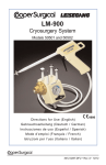
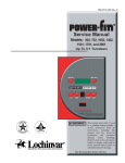
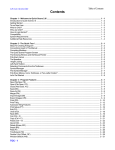
6 720 811 153-00.1O CRC200 Comfort Room Controller 6 720 811 158 (2015/02) User manual 2 | Contents Contents 1 Explanation of symbols and safety instructions . . . . 2 1.1 Guideline to symbols . . . . . . . . . . . . . . . . . . . . . . . . 2 1.2 Safety instructions . . . . . . . . . . . . . . . . . . . . . . . . . 3 2 Product Description . . . . . . . . . . . . . . . . . . . . . . . . . . . . 2.1 Notes on functional scope . . . . . . . . . . . . . . . . . . . 2.2 Function as controller . . . . . . . . . . . . . . . . . . . . . . . 2.3 Certificates . . . . . . . . . . . . . . . . . . . . . . . . . . . . . . . 2.4 Applicability of the technical documentation . . . . 2.5 Operation after a power failure . . . . . . . . . . . . . . . 1 Explanation of symbols and safety instructions 1.1 Guideline to symbols Warnings Warnings in this document are identified by a warning triangle printed against a grey background. Keywords at the start of a warning indicate the type and seriousness of the ensuing risk if measures to prevent the risk are not taken. 3 3 3 3 3 3 3 Overview of controls and symbols . . . . . . . . . . . . . . . . 4 4 Getting started . . . . . . . . . . . . . . . . . . . . . . . . . . . . . . . . 6 4.1 Changing the room temperature . . . . . . . . . . . . . . 6 4.2 More settings . . . . . . . . . . . . . . . . . . . . . . . . . . . . . . 7 5 Working with the MENU . . . . . . . . . . . . . . . . . . . . . . . . . 9 5.1 Menu structure . . . . . . . . . . . . . . . . . . . . . . . . . . . 10 5.2 Overview of main menu . . . . . . . . . . . . . . . . . . . . 10 5.3 Adapting the settings for Heating with the time program (automatic mode) . . . . . . . . . . . . . . . . . 11 5.4 Changing the settings for water heating . . . . . . . 14 5.5 Setting up a vacation program . . . . . . . . . . . . . . . 15 5.6 Displaying information about the system . . . . . . 17 5.7 General settings . . . . . . . . . . . . . . . . . . . . . . . . . . 18 The following keywords are defined and can be used in this document: • DANGER indicates a hazardous situation which, if not avoided, will result in death or serious injury. • WARNING indicates a hazardous situation which, if not avoided, could result in death or serious injury. • CAUTION indicates a hazardous situation which, if not avoided, could result in minor to moderate injury. • NOTICE is used to address practices not related to personal injury. Important information This symbol indicates important information where there is no risk to people or property. Additional symbols 6 Energy-saving tips . . . . . . . . . . . . . . . . . . . . . . . . . . . . 19 Symbol Function ▶ Sequence of steps 7 FAQ . . . . . . . . . . . . . . . . . . . . . . . . . . . . . . . . . . . . . . . . . 19 Cross-reference to other points in this document or to other documents 8 Troubleshooting . . . . . . . . . . . . . . . . . . . . . . . . . . . . . . 20 8.1 Eliminating “sensed” faults . . . . . . . . . . . . . . . . . . 20 8.2 Eliminating displayed faults . . . . . . . . . . . . . . . . . 21 • Listing/list entry – Listing/list entry (2ndlevel) Tank loading Flashing indication display (e. g. flashing ON) 9 Environmental protection/disposal . . . . . . . . . . . . . . 22 6 720 811 158-11.2O 10 Setup log . . . . . . . . . . . . . . . . . . . . . . . . . . . . . . . . . . . . . 23 Table 1 Additional symbols Technical terms . . . . . . . . . . . . . . . . . . . . . . . . . . . . . . . 24 Index . . . . . . . . . . . . . . . . . . . . . . . . . . . . . . . . . . . . . . . . 25 6 720 811 158 (2015/02) CRC200 Product Description | 3 1.2 Safety instructions These operating instructions are intended for the heating system user. ▶ Read and retain the operating instructions (heat source, modules etc.) prior to operation. ▶ Observe safety instructions and warnings. Designated use ▶ Use the product only to control heating systems in residential houses or apartments. Any other use is considered improper. Any resulting damage is excluded from the manufacturer's warranty. Inspection and maintenance Regular inspection and maintenance are prerequisites for safe and environmentally compatible operation of the heating system. We recommend that you enter into a contract for the annual inspection and demand-dependent maintenance with an authorized contractor. ▶ Have work carried out only by an authorized contractor. ▶ If any faults are discovered, have them remedied immediately. Risk of damage from frost The system can freeze if it is switched off: ▶ Observe the instructions for frost protection. ▶ Always leave the system switched on for additional functions, e. g. water heating or anti-seize protection. ▶ Have faults rectified immediately. Risk of scalding at the hot water draw-off point ▶ If hot water temperatures above 60 °C are set or if thermal disinfection is activated, a mixer must be installed. If in doubt, ask your contractor. 2 Product Description The user interface CRC200 permits simple operation of the heating system. The desired room temperature can be set in the room by turning the dial. Automatic operation with the adjustable time program assures energy-saving operation by reducing the room temperature at specified times or shutting off the heating entirely. This method of controlling the heating optimizes thermal comfort while minimizing energy consumption. DHW heating can be adjusted conveniently and controlled efficiently. 2.1 Notes on functional scope The functional scope and thus the menu structure of the user interface are determined by the structure of the system. Your attention is drawn to the importance of the system structure at the relevant places in these instructions. The control ranges and factory settings may differ from the information in these instructions, depending on the system installed at the site. Consult your contractor if you have further questions. 2.2 Function as controller Water heating settings for the storage tank and thermal disinfection are made in the first heating zone on the CRC200. The CRC200 functions as a Room temperature-dependent controller which means automated control of the heating based on the room temperature. 2.3 Certificates This product has been tested and is certified for both the US and Canadian markets, and meets all applicable US and Canadian standards. 2.4 Applicability of the technical documentation All information related to BUS systems and heating controllers contained in the technical documentation of e.g. heat sources applies also to the present user interface. 2.5 Operation after a power failure No settings are lost in the event of a brief power failure or if the heat source is shut down for short periods of time (min. four hours power reserve after 1½ hour of operation). When the power supply is restored, the user interface resumes operation. If the shutdown period is prolonged, the settings for the time of day and the date might have to be made again. No other settings are required. CRC200 6 720 811 158 (2015/02) 4 | Overview of controls and symbols 3 Overview of controls and symbols 1 2 5 3 4 6 720 809 984-40.1O Fig. 1 Controls Item Element 1 Designation Explanation dial ▶ Turn to change a setting or select a menu/menu item. ▶ Press to open a menu/menu item or confirm a setting/message. 2 auto auto button ▶ Press to activate the automatic mode. 3 man man button ▶ Press to activate the hold mode (manual operation) 4 Back button ▶ Press to return to the higher menu level or discard a setting. ▶ Press for an extended period of time to close the main menu. 5 Table 2 menu menu button ▶ Press to open the main menu. Controls 6 720 811 158 (2015/02) CRC200 Overview of controls and symbols | 5 2 3 12:31 4 Tu 7 3 Recirculation auto 1 1 man 5 6 8 6 720 811 158-02.2O Fig. 2 Item Symbols on the display (sample figures) Symbol 1 Designation Explanation Value display Display of the current room temperature and input field for the desired room temperature Display of information values and input field for setting values 2 pm/am Time of day 3 – Text line Afternoon/morning with 12-hour format (factory setting 12-hour format) Time of day (e. g. 02:03pm) and current day of the week (e. g. Mo) Display of menu items, settings, info texts etc. Additional texts are identified by direction arrows and displayed by turning the dial. 4 Operating mode Automatic Mode Active (according to time program) Hold Mode Active (manual operation) Heating Circuit Active Setback Mode Active 5 Segment display Solid segments: time set for operating mode today (1 segment = 30 min) 6 Operating state Burner operational 7 Menu Heating Menu with settings for the heating system Menu DHW Menu with settings for water heating Menu Holiday Menu with settings for vacation program Menu Info Menu to display current information about the heating system, e. g. heating, hot water Menu Settings Menu with general settings, e. g. language, time/date, formats Units line Physical units for the displayed values, e. g. in the “Information” menu. The following units can be shown: ( ) No segments: time set for setback mode today (1 segment = 30 min) 8 Table 3 CRC200 – Symbols on the display 6 720 811 158 (2015/02) 6 | Getting started 4 Getting started An overview of the structure of the main menu and the position of the individual menu items can be found on page 10. 4.1 Each of the following descriptions takes the standard display as its starting point ( page 5, Fig. 2 at left). Changing the room temperature Operation Result Manual operation Auto mode To check the current required room temperature. If the automatic mode is active ( displayed): ▶ Press the auto key. The desired room temperature then appears on the display for a few seconds. How long the current setting applies (time to next switching time) appears next for a few seconds. Set Room Temp 6 720 811 158-03.1O If the hold mode is active ( displayed): ▶ Press the man key. The desired room temperature then appears on the display for a few seconds. An indication that the current setting is being held (unlimited time) then appears on the display for a few seconds. Hold 6 720 811 158-04.2O Auto mode If it is too cold or too warm for you today: Change the room temperature temporarily ▶ Turn the dial in order to set the desired room temperature. ▶ Press the dial (or wait a few seconds). The setting value stops flashing. The user interface operates with the modified settings. The change applies until the next switching time in the active time program is reached ( Chapter 5.3, Page 11). The temperature stored in the automatic mode then becomes active again. to 11:00 pm 6 720 811 158-05.1O Should it be permanently too cold or too hot for you: Change the required room temperature for the Heating or Setback mode Auto mode ▶ Press the menu key to open the main menu. ▶ If necessary, turn the dial to highlight the Heating menu. ▶ Press the dial to open the Heating menu. Temperatures Notice: Continued on page 7. Table 4 6 720 811 158-06.1O Getting started – Room temperature 6 720 811 158 (2015/02) CRC200 Getting started | 7 Operation Result Auto mode Notice: Continued from page 6. ▶ Press the dial to open the Temperatures menu. ▶ Turn the dial to select the menu item Heating or Setback and press the dial. The current setting appears and flashes. ▶ Turn the dial to set the desired room temperature for the selected operating mode and press the dial. The setting value stops flashing. The user interface operates with the modified settings. Setback 6 720 811 158-07.1O Manual operation If you require a room temperature for a period of time which deviates from the temperatures set for heating or setback: Activate manual operation and set the required room temperature ▶ Press the man key. The user interface will now constantly maintain the set temperature entered for manual operation. ▶ Wait a few seconds until the default display appears again or press the dial twice. ▶ Turn the dial to set the desired room temperature and press the dial (or wait a few seconds). The setting value stops flashing. The user interface operates permanently and for an unlimited period of time with the modified setting (without setback). Table 4 4.2 Set Room Temp 6 720 811 158-08.1O Getting started – Room temperature More settings Operation Result If you need hot water outside of the times set in the time program: Activate immediate tank charging (immediate hot water function) ▶ ▶ ▶ ▶ Press the menu key to open the main menu. Turn the dial to highlight the DHW menu. Press the dial to open the selected menu. Press the dial. The current setting appears and flashes. ▶ Turn the dial to set ON and press the dial. Water heating (tank heating or instantaneous flow heating) becomes active immediately. After heat-up, immediate tank charging switches off again. Tank loading 6 720 811 158-11.2O Setting the time and date ▶ ▶ ▶ ▶ Press the menu key to open the main menu. Turn the dial to highlight the Settings menu. Press the dial to open the selected menu. Turn the dial to select the Time/Date menu and press the dial. The menu item Time of Day is displayed. Time of Day 6 720 811 158-14.1O Table 5 CRC200 Getting started – More settings 6 720 811 158 (2015/02) 8 | Getting started Operation ▶ Press the dial. The input field for the hour setting starts to flash. ▶ Turn the dial to set the hour and press the dial. The input field for the minute setting starts to flash. ▶ Turn the dial to set the minutes and press the dial. Result Time of Day 6 720 811 158-15.1O ▶ Turn the dial to select the menu item Date and press the dial. The first input field for the date starts to flash in the text line (observe the setting in the Settings > Format > Date format menu). ▶ Set the month, day and year in the same way as the hours and minutes. ▶ Press the dial. The setting value stops flashing. The user interface operates with the modified settings. 07/20/2014 6 720 811 154-16.1O To prevent the user interface settings from being modified inadvertently: Activate key block ▶ Press and hold the dial and auto key simultaneously for a few seconds until Key Lock appears in the text line. ▶ If a control element is actuated while key block is active, Key Lock appears in the text line. Key Lock Canceling key block: ▶ Press and hold the dial and auto key simultaneously for a few seconds until Key Lock no longer appears in the text line. 6 720 811 158-17.1O To change the language of the display texts: Set language ▶ ▶ ▶ ▶ Press the menu key to open the main menu. Turn the dial to highlight the Settings menu. Press the dial to open the selected menu. Press the dial. The currently set language flashes in the text line and appears in abbreviated form in the value display. ▶ Turn the dial until the desired language appears and press the dial. The selected language is active immediately. english 6 720 811 158-18.1O If your day/night pattern changes (e. g if you work shifts): Adapt the time program Enter setting in the Heating > Time program menu ( Table 10, Page 12). Heat begin1 6 720 811 158-21.1O Table 5 Getting started – More settings 6 720 811 158 (2015/02) CRC200 Working with the MENU | 9 5 Working with the MENU Opening the menu ▶ Press the menu key to open the main menu. ▶ Turn the dial to highlight the the desired menu, e. g. Settings. ▶ Press the dial to open the selected menu. ▶ Turn the dial to select a submenu, e. g. Settings > Format. ▶ Press the dial to open the selected menu. Changing the setting ▶ Turn the dial in order to select the desired menu item, e. g. Format > Contrast. ▶ Press the dial. The current setting appears and flashes. ▶ Turn the dial to set a value. ▶ Press the dial. The setting value stops flashing. The user interface operates with the modified settings. Closing the menu ▶ Press the Back key to return to the next higher menu. -or▶ Press and hold the Back key for a longer period of time to close the main menu and return to the room temperature display immediately. Table 6 CRC200 Working with the main menu 6 720 811 158 (2015/02) 10 | Working with the MENU 5.1 Menu structure Main Menu Heating Holiday Settings Temperatures Holiday Prog. english Heating Info Time/Date Setback Heating 1) Time of Day Time program Outdoor Temp. Date Reset Sched. Operat. stats Time correc. DHW Room Temp. Tank loading Format DHW Mode Date format Operat. stats Time Format Recirculation 2) Set temp. Temp. Format Disinfection 2) Actual Temp. Sensor calib. Contrast Service 3) 6 720 811 156-17.2O Fig. 3 1) 2) 3) Main menu summary Set language. Available only on the user interface for heating zone 1. Settings in the service menu may only be changed by a contractor (hidden by default). 5.2 Overview of main menu Menu Purpose of the menu Page Heating Change the room temperatures 11 and time program for the heating system permanently. DHW Change the hot water 14 temperature and settings for the hot water system. Holiday Settings for operating the system during prolonged periods of absence (vacation program). 15 Info Display the current temperatures and operating status of the system. 17 Settings Change the general settings, e. g. language, time or date. 18 Table 7 6 720 811 158 (2015/02) CRC200 Working with the MENU | 11 5.3 Adapting the settings for Heating with the time program (automatic mode) Heating menu Normally, the time program provides the best heating comfort. If the temperatures or the time program do not meet your needs, you can adapt the settings. Setting the temperatures for the operating modes in the automatic mode A detailed description of how to change the temperatures can be found in Chapter 4.2, Page 7. Menu Heating > Temperatures Menu item Description Heating Desired room temperature for the heating mode; if automatic mode is active, the time program will switch to this temperature at the start of every heating phase (42 °F ... 86 °F / 5.5 °C ... 30.0 °C). This temperature cannot be set lower than the temperature for the setback mode + 1 °F (+ 0.5 °C). Setback Desired room temperature for the setback mode; if automatic mode is active, the time program will switch to this temperature at the start of every setback phase (41 °F ... 85 °F / 5.0 °C ... 29.5 °C) or OFF. This temperature cannot be set lower than the temperature for the heating mode – 1 °F ( – 0.5 °C). Table 8 Temperature settings in the heating menu Adapting the start of heating and start of setback in the Time program Six switching times are available under each menu item in the Time program menu (day of week or group of days). Using these switching times, three heating phases per day can be established. Heat begin1 represents the first switching time for the heating mode and defines when the first heating phase starts. Strt setback1 represents the first switching time for the setback mode and defines when the first heating phase ends. To set the same switching times for several days of the week, set the switching times under Mo-Fr first. Then adapt the time program for the individual days of the week that differ and for Saturday and Sunday. The switching times in the time program can be set in 15-minute increments. In the segment display, each segment corresponds to one half-hour. As a result, a discrepancy of 15 minutes may occur in the segment display of the time program. This discrepancy has no effect on the time program. A detailed description of how to modify the time program can be found in Table 10, Page 12. Menu Heating > Time program Menu item Description Mon-Fri It is possible to set 6 switching times for each day (3 switching times for heat begin and 3 switching times for setback begin). The minimum duration of a heating phase is 30 minutes. Saturday Sunday Monday Tuesday The default settings are: Wednesday • Mon-Fri: Heat begin1: 06:00am to Strt Thursday setback1: 11:00pm Friday • and Sunday: Heat begin1: 08:00am to Strt setback1: 11:00pm This means that you are heating from 11:00pm in the evening until 06:00am on the following day to the setback temperature only (Saturday and Sunday until 08:00am). Table 9 CRC200 Time program settings in the heating menu 6 720 811 158 (2015/02) 12 | Working with the MENU The following table shows how to activate or modify the time program. Operation Result Activate automatic mode with time program If manual operation is active ( displayed): ▶ Press the auto key. The user interface controls the room temperature in the automatic mode on the basis of the time program. 12:41 We 6 720 811 158-19.1O Open time program for several days for one individual weekday ▶ Press the menu key to open the main menu. The Heating menu is highlighted. ▶ Press the dial to open the selected menu. ▶ Turn the dial to select the Time program menu and press the dial. The Time program menu is open, the Mon-Fri menu item is displayed. Mon-Fri 6 720 811 158-20.1O ▶ Turn the dial to select Mon-Fri (change switching times for all weekdays together) or Saturday ... Friday (change switching times for individual weekdays). ▶ Press the dial. The selected menu item is open, Heat begin1 is displayed. Heat begin1 6 720 811 158-21.1O Set heat begin or setback begin earlier or later (move switching time) ▶ Open time program for all weekdays or one individual weekday. ▶ Select the switching time and press the dial. The hour currently set for the switching time and the associated segment in the segment display start to flash. ▶ Turn the dial to move the switching time. The setting in the value display changes in 15-minute increments and in the segment display in 30-minute increments. ▶ Press the dial. The user interface operates with the modified setting. Strt setback1 6 720 811 158-22.1O Table 10 Activating and modifying the time program 6 720 811 158 (2015/02) CRC200 Working with the MENU | 13 Operation Result Add a new heating phase (e. g. Heat begin2 to Strt setback2) If all six switching times in the time program are not being used, a new heating phase can be added. ▶ Open time program for all weekdays or one individual weekday. ▶ Turn the dial to select Heat begin2 and press the dial. The new switching time is added. The hour and associated segment in the segment display start to flash. Heat begin2 6 720 811 158-23.1O ▶ Turn the dial to set Heat begin2, e. g. to 02:00pm and press the dial. The new heating phase is added with a duration of one half-hour. Strt setback2 is set to 02:30pm. If necessary, move Strt setback2 to later, e. g. to 11:00pm. The user interface operates with the modified settings. Strt setback2 6 720 811 158-24.1O Interrupt heating phase with setback phase (e. g. add setback phase between Heat begin2 and Strt setback2) ▶ ▶ ▶ ▶ Open time program for all weekdays or one individual weekday. Turn the dial to select Strt setback2 (end of the heating phase being interrupted). Set Strt setback2 to the start of the interruption, e. g. 06:00pm. Add a new heating phase and set heat begin and setback begin, e. g. Heat begin3 (09:00pm) to Strt setback3 (11:00pm). The user interface automatically sorts the heating phases chronologically. The user interface operates with the modified settings. Strt setback3 6 720 811 158-25.1O Delete a heating phase (e. g. Heat begin2 to Strt setback2) ▶ Open time program for all weekdays or one individual weekday. ▶ Turn the dial to select Strt setback2 and press the dial. The hour currently set for the switching time and the associated segment in the segment display start to flash. ▶ Turn the dial to set Strt setback2 to the same hour as Heat begin2. Delete? appears in the text line ▶ Press the dial. The heating phase is deleted. The user interface operates with the modified settings. Delete? 6 720 811 158-26.1O Delete a setback phase (e. g. Strt setback1 to Heat begin2) ▶ Open time program for all weekdays or one individual weekday. ▶ Delete the heating phase before Strt setback1 (or after Heat begin2). The user interface automatically sorts the heating phases chronologically. ▶ Set Heat begin1 to earlier (or Strt setback1 to later). The setback phase is deleted. The user interface operates with the modified settings. Heat begin1 6 720 811 158-27.1O Table 10 Activating and modifying the time program CRC200 6 720 811 158 (2015/02) 14 | Working with the MENU Resetting the time program to the factory settings Menu Heating > Reset Sched. Hot water menu Menu item Description Menu item Description Tank loading Reset Sched. With the aid of the YES setting, an individual time program can be reset to the factory settings. All other settings are retained. If immediate tank charging is activated (ON), water heating or temperature maintenance is active immediately. Mode Operating modes for water heating, Page 14. Recirculation Recirculation makes hot water available immediately at the hot water taps. • If ON is set, hot water is pumped through the recirculation line briefly once or several times per hour. • If AUTO is set, hot water is pumped through the recirculation line briefly once or several times per hour at the times water heating or keeping water hot is active. • Set OFF to save as much energy as possible. Disinfection1) Thermal disinfection safeguards the hygienic quality of the hot water. If AUTO is set, the hot water is heated to 158 °F (70 °C) once every Tuesday starting at 2:00am (at night). Table 11 5.4 Changing the settings for water heating CAUTION: Health hazard due to legionella! ▶ At lower hot water temperatures, activate thermal Disinfection. WARNING: Risk of scalding! If thermal disinfection is activated to prevent legionella, the hot water is heated once to 158 °F (70 °C) (Tuesday night at 02:00am). The hot water temperature is set at the factory to 140 °F (60 °C). There is a risk of scalding at the taps if the temperature is set higher than this. ▶ Make sure that a mixer is installed. If in doubt, ask your contractor. Table 12 Operating modes for water heating The following statements refer to a request for hot water from this CRC200. Water heating or temperature maintenance remains active even if a request comes from a different CRC200. The operating modes for hot water can be used independently of the active operating mode for heating. • The automatic mode for water heating is active when AUTO appears in the value display under the menu item Mode. There is no separate time program for water heating. The time program for heating also specifies the switching times for water heating. Water heating is active for a half an hour before, during and after each heating phase (all heating circuits). The time program for water heating is also in effect during manual operation of the heating system. • Continuous water heating or temperature maintenance is active when Mode appears in the value display under the menu item ON. • There is no water heating or temperature maintenance when Mode appears in the value display under the menu item OFF. A detailed description of how immediate tank charging is activated and how the hot water temperature is set can be found in Chapter 4.2, Page 7. Proceed as described in Table 6 on page 9 to change the other settings. 6 720 811 158 (2015/02) CRC200 Working with the MENU | 15 5.5 Setting up a vacation program NOTICE: System damage! ▶ After a prolonged period of absence, check the operating pressure of the heating system at the pressure gauge. To save energy, we recommend that you use the vacation program during a prolonged period of absence. Holiday The vacation program is activated automatically at 6 720 811 158-28.1O the previously set vacation start date. While the the vacation program is running, the text line displays Holiday. The current room temperature appears in the value display. The factory settings guarantee energy-saving and safe operation during your vacation. The room temperature used for heating between the vacation start and vacation end dates corresponds to the setback temperature in the automatic mode (see Changing the setting Chapter 4.2, page 7). If the CRC200 is used as the controller, water heating or temperature maintenance is off while the vacation program is active. After the end of the vacation program, the user interface operates again with the set time program (heating and setback phases). Vacation menu Menu item Functional description Holiday Prog. If the setting value is set to ON, the heating system automatically operates energy efficiently from the vacation begin to the vacation end date ( Tab. 14). Table 13 The following table shows how to activate, set, interrupt or prematurely end the vacation program. Operation Result Open the vacation menu ▶ Press the menu key to open the main menu. ▶ Turn the dial to highlight the Holiday menu. ▶ Press the dial to open the selected menu. The menu item Holiday Prog. is displayed. Holiday prog. 6 720 811 158-29.1O Activate the vacation program and set the vacation time ▶ Open the Holiday menu. ▶ Press the dial. The setting value OFF starts to flash in the input field. ▶ Turn the dial to select ON and press the dial. The text line displays the vacation begin date (factory setting for 1st vacation day = current date) and the vacation end date (factory setting for last day = one week after the current date). The input field for the day vacation begins starts to flash. ▶ Turn the dial to set the month vacation begins and press the dial. The month that vacation begins is changed; the input field for the day vacation begins starts the flash. ▶ Turn the dial to set the day vacation begins and press the dial.1) The day that vacation begins is changed; the input field for the month vacation ends starts to flash. 07/20/ - 07/27/ 6 720 811 158-30.1O 08/06/ - 07/27/ 6 720 811 158-31.1O Table 14 Activating, setting, interrupting or prematurely ending the vacation program CRC200 6 720 811 158 (2015/02) 16 | Working with the MENU Operation ▶ Turn the dial to set the month vacation ends and press the dial. The month that vacation ends is changed; the input field for the day vacation ends starts to flash. ▶ Turn the dial to set the day vacation ends and press the dial.2) The user interface operates with the modified settings. The vacation program is activated automatically on set vacation begin date. The vacation period for the example shown runs from 12:00am on 08/06/ to 12:00am on 08/22/. Result 08/06/ - 08/21/ 6 720 811 158-32.1O Canceling vacation program ▶ Press the man key. The user interface will now constantly maintain the set temperature entered for manual operation. Hot water is available only if immediate tank charging is active or the hot water operating mode is ON. ▶ If necessary, turn the dial to set the desired room temperature and press the dial (or wait a few seconds). The user interface will now constantly maintain the new set room temperature. ▶ Press the auto key to resume the vacation program. 12:55 We 6 720 811 158-33.1O Canceling the vacation program early ▶ Open the Holiday menu. ▶ Press the dial. The setting value ON starts to flash in the input field. ▶ Turn the dial to select OFF and press the dial. The vacation program is ended prematurely. The setting values for the vacation begin and vacation end dates are deleted. Holiday prog. 6 720 811 158-34.1O Table 14 Activating, setting, interrupting or prematurely ending the vacation program 1) If the vacation begin date precedes the current date, the year vacation begins is the coming year. 2) If the vacation end date precedes the vacation begin date, the year vacation ends is the year following the year vacation begins. 6 720 811 158 (2015/02) CRC200 Working with the MENU | 17 5.6 Displaying information about the system Menu Info > Heating Menu item Description (possible displays) Outdoor Temp. The currently measured outdoor temperature, e . g. – 23 °F ( – 5.0 °C). This menu item is displayed only if an outdoor temperature sensor is installed. Operat. stats The heating system can have four different operating conditions. The current status of each heating zone assigned is displayed: • If OFF is displayed, the heating is off, but frost protection remains active. • If Heating or Setback is displayed, the heating system is operating in automatic mode. Based on the time program, the system heats to the temperature set for the particular operating mode. • If Manual is displayed, the heating system operates in the manual mode. ▶ Turn the dial to select a menu item, e. g. Actual Temp. (= current hot water temperature) Room Temp. The currently measured room temperature, e. g. 72 °F (22.0 °C). If no information appears in the value display: ▶ Press the dial. The information for the selected menu item appears. ▶ Press the Back key to return to the menu item. Table 16 Info menu The current system values and the active operating status can be displayed easily via the Info menu. No changes can be made here. The DHW menu is displayed only if the user interface is installed and set up appropriately in a system with water heating. Opening the menu ▶ ▶ ▶ ▶ ▶ Press the menu key to open the main menu. Turn the dial to highlight the Info menu. Press the dial to open the info menu. Turn the dial to select a submenu, e. g. DHW. Press the dial to open the selected menu. Display information Closing the menu ▶ Press the Back key to return to the next higher menu. ▶ Press the Back key for an extended period of time to close the main menu. Table 15 Operating the info menu Menu Info > DHW Menu item Description (possible displays) Operat. stats Display of the current operating status of water heating: ON or OFF Set temp. Desired hot water temperature, e . g. 122 °F (50.0 °C). Actual Temp. The currently measured hot water temperature, e. g. 117 °F (47.0 °C). Table 17 CRC200 6 720 811 158 (2015/02) 18 | Working with the MENU 5.7 General settings Settings menu All relevant settings for the end customer are combined under the general settings. This starts with language selection, continues through all time settings and format selections and ends with sensor calibration and display contrast. Changing the language A detailed description of how to change the language can be found in Table 5, Page 7. Setting the time correction correctly Example of calculating the time correction value, with a time of day deviation of approx. – 6 minutes per year (the clock in the user interface is 6 minutes slow): • – 6 minutes per year = – 360 seconds per year • 1 year = 52 weeks • – 360 seconds : 52 weeks = – 6.92 seconds per week • Increase the value of the time correction by 7 s/week. Settings > “Language”1) menu Setting output formats and properties of the user interface Proceed as described in Table 6 on page 9 to change the settings in the Format menu. Menu item Functional description Menu Settings > Format Language1) The language used for menus and menu items can be changed. Menu item Table 18 1) The set language appears on the display instead of the text “Language”. Setting the time and date A detailed description of how to set the time and date can be found in Table 5, Page 7. Proceed as described in Table 6 on page 9 to change the other settings. No settings are lost in the event of a brief power failure or if the heat source is shut down for short periods of time. When the power supply is restored, the user interface resumes operation. If the shutdown period is prolonged, the settings for the time of day and the date might have to be made again. No other settings are required. Menu Settings > Time/Date Menu item Time Format A 24-hour format (24h) and a 12-hour format (12h, am and pm) are available for displaying the time. Temp. Format The units °C and °F are available for displaying the temperatures. Sensor calib. If the room temperature displayed by the user interface is not accurate, correct the discrepancy by up to 5.4 °F (3 °C), à “Calibrating the room temperature sensor (Sensor calib.)” Contrast If what appears on the display is hard to see because of the lighting conditions, adjust the contrast of the display (36 % ... 64 %). Functional description Time of Day Set the current time. Date Set the current date. Time correc. Time correction of the internal clock of the user interface in seconds per week ( – 20 s/ week ... 20 s/week). Only the unit s (seconds) appears on the display instead of s/week (seconds per week) ( “Setting the time correction correctly”). Table 19 6 720 811 158 (2015/02) Functional description Date format Display of the date in all menus (DD.MM.YYYY or MM/DD/YYYY), where: D = day, M = month, Y = year. If indication of the year is not needed (e. g. in the vacation program), only DD.MM. or MM/DD/ appears. Table 20 Calibrating the room temperature sensor (Sensor calib.) ▶ Place a suitable thermometer close to the user interface so that they are both subject to the same heat influences. ▶ Keep heat sources such as direct sunlight and body heat, etc., away from the user interface and the thermometer for one hour. ▶ Open the Sensor calib. menu. ▶ Turn the dial to set the correction value for the room temperature. For example, if the thermometer is showing a temperature 1.2 °F (0.7 °C) higher than the user interface, increase the setting value under Sensor calib. by 1.2 °F (0.7 K). ▶ Press the dial. The user interface operates with the modified settings. CRC200 Energy-saving tips | 19 6 Energy-saving tips Economy heating • Use the time program by activating automatic mode. Set the required room temperatures for the heating and setback operating modes in accordance with your personal temperature preferences. Adjust the time programs to suit your lifestyle. – Heating mode = Comfortable living environment – Setback mode = Active living, away from home or asleep • Keep the user interface away from external heat sources (e. g. sunlight, tiled stoves, etc.). Otherwise there may be undesired fluctuations in the room temperature. • Never position large objects such as a sofa immediately in front of radiators (maintain a clearance of at least 50 cm). Otherwise, the heated air cannot circulate and heat the room adequately. • If you reduce the room temperature by 2 °F (1 K / 1 °C), you can save up to 6 % energy. However, allowing the room temperature of heated rooms to drop below + 59 °F (+ 15 °C) daily is not recommended. This way, the walls cool off too much. In the heat-up phase, the room climate is disturbed by the cold walls, which continue to emit cold. If you further increase the room temperature, more energy is used than with the same amount of heat supply. • With good heat insulation of your building, it is possible that after a heating phase the desired room temperature for the setback mode will not be reached. Nevertheless, energy is being saved as the heating system stays off. You save still more energy if you set the switching time for the setback mode earlier. Ventilating properly Briefly open the windows fully instead of only a little. If the windows are only open a little, heat is constantly drawn out of the room without significantly improving the indoor air. Water heating on demand • If the heating phases and the times at which hot water is required are closely aligned, use the time program for water heating in automatic mode as well. • Set the hot water temperature as low as possible. This saves a lot of energy without noticeably impairing DHW convenience. 7 FAQ Why does the room temperature measured with a separate thermometer not correlate with the displayed room temperature? Various different factors influence the room temperature. If the user interface is installed on a cold wall, it will be affected by the cold temperature of the wall. If it is mounted in a warm part of the room, such as close to a fireplace or chimney, it will be influenced by the heat there. Therefore, a separate thermometer can indicate a different room temperature than that set at the user interface. When comparing the displayed room temperature with temperatures measured by another thermometer, it is important to remember the following: • • • The separate thermometer and the user interface must be physically close to each other. The separate thermometer must be accurate. When comparing, do not measure the room temperature when the system is heating up, as the two devices may react at different speeds to the change in temperature. If you have followed these instructions and you can still detect a discrepancy, you can now calibrate the room temperature display ( page 18). Why do the radiators get (too) hot when the outside temperature is relatively high? Even in the summer, the radiators may be heated for a short time under specific circumstances: namely, when the pump is started up automatically at a predefined interval, to prevent it from "seizing up" (jamming). If the pump happens to be started up immediately after water heating, the unused residual heat is dissipated via the heating circuit and the radiators. Why does the pump run at night, even though the home is not being heated at all or only very little? The setback type Reduced operation is set permanently for the user interface. In order to maintain a lower room temperature, the pump continues to run even if the heating is reduced. The measured room temperature is higher than the required room temperature. Why is the heat source still running? The heat source may be heating hot water. CAUTION: Health hazard due to legionella! ▶ At lower hot water temperatures, activate thermal Disinfection. CRC200 6 720 811 158 (2015/02) 20 | Troubleshooting 8 Troubleshooting 8.1 Eliminating “sensed” faults Problem A “sensed” fault can have various causes, which can usually be eliminated by taking simple steps. If it is too cold or hot for you, the following table will help you eliminate these “sensed” faults. Problem Possible cause Required room Temperatures set temperature not too low. achieved Supply temperature Set supply controller on heat temperature source set too low. controller higher ( operating instructions of the heat source). Air in the system. Heat-up takes too long Bleed all air from the radiators and system. Wrong heating zone Call approved response. contractor or customer service. Required room Radiators become too hot. temperature greatly exceeded Set thermostat(s) in adjoining rooms lower. Set the required room temperature for Heating lower. Unfavorable user Call approved interface installation contractor or location, e. g. customer service. external wall, near window, in draft, ... Excessive room temperature fluctuations Temporary influence Call approved of external heat on contractor or the room, e. g. from customer service. solar exposure, room lighting, TV, fireplace etc. Temperature rises instead of dropping Incorrect time set. Measure Incorrect or no control For instance, Call approved connection between contractor or user interface and customer service. heat source faulty. Domestic hot water tank does not heat up Hot water temperature1) on heat source set too low. Set the hot water temperature1) higher. Time program for heating set and water heating in automatic mode. Change time program for heating or operating mode for water heating. Measure Set the required room temperatures higher. Possible cause The building retains Set an earlier Room temperature too a lot of heat. switching time for high during Setback. Setback operating mode The set system Call approved configuration for hot contractor or water heating does customer service. not fit the heating system. The hot water at Mixer set lower than If you are in doubt, the required hot the taps is not contact your water temperature. contractor to come reaching the required and check the mixer temperature. setting. Table 21 Eliminating “sensed” faults 1) See operating instructions of the heat source for further information. Set the time. Table 21 Eliminating “sensed” faults 6 720 811 158 (2015/02) CRC200 Troubleshooting | 21 8.2 Eliminating displayed faults NOTICE: Risk of system damage due to freezing! The system can freeze up if it is taken out of service due to a fault shutdown. ▶ Use Tab. 22 to check if the fault can be fixed. ▶ If the fault cannot be fixed, contact your contractor immediately. A fault in your system is indicated on the display of Fault the user interface. If there are multiple faults, the fault with the highest priority will be displayed. The fault code and sub-code are displayed 6 720 811 158-35.1O alternately. The codes inform your contractor about the possible cause. Confirm a fault (press the dial) to switch to the room temperature display. The fault is displayed again automatically after 60 minutes if it is still active. The cause can be a fault on the user interface, in a component, in an assembly or on the heat source. Subcode Fault code The system keeps operating as much as possible; in other words, heating of the home can continue. Cause or fault description Display is blank Testing sequence/Cause Measure System is switched off. ▶ Switch on the system. The power supply to the user interface has ▶ Check that the user interface is correctly seated in its wall bracket. been interrupted. A6x 1010 No communication via BUS connection EMS in heating zone x – ▶ Check that the user interface is correctly seated in its wall bracket. A6x 1038 Invalid time/date in heating zone x Date/time not yet set Set date/time Prolonged loss of power supply Avoid voltage failures 3061 No communication with 3062 controller in heating 3063 zone x 3064 – ▶ Check that the user interface is correctly seated in its wall bracket. A6x Hxx H07 – Maintenance required. The system keeps ▶ Make arrangements to have the operating as far as possible. system serviced by your contractor. 1017 Water pressure too low Water pressure in the system is too low. ▶ Top up the heating water as described This level is only displayed if your system in the heat source operating is equipped with a digital pressure sensor. instructions. Table 22 Table with fault and service displays If a fault persists or is not listed here: ▶ Call an authorized contractor or customer service and give them the fault code and sub-code, as well as the ID no. of the user interface. _ _ _ Table 23 Your contractor must enter the ID no. of the user interface here during installation. CRC200 6 720 811 158 (2015/02) 22 | Environmental protection/disposal Fault affecting the heat source Heat source faults are always displayed on the heat source. If there is a BUS connection between the user interface and the heat source, faults are also displayed on the user interface. If in doubt, ask your contractor about the type of connection. Locking faults on the heat source can be rectified by performing a reset. ▶ Reset the heat source. See the operating instructions for the heat source for additional information about eliminating faults affecting the heat source. ▶ If the fault cannot be rectified by a reset, contact your contractor. 9 Environmental protection/disposal Environmental protection is one of the fundamental company policies of the Bosch Group. We regard quality of performance, economy and environmental protection as equal objectives. Environmental protection laws and regulations are strictly adhered to. To protect the environment, we use the best possible technology and materials taking into account economic points of view. Packaging For the packaging, we participate in the country-specific recycling systems, which guarantee optimal recycling. All packaging materials used are environmentally-friendly and recyclable. Old appliances Old appliances contain resources that should be recycled. The components are easy to separate and the plastics are marked. This allows the various components to be sorted for appropriate recycling or disposal. 6 720 811 158 (2015/02) CRC200 Setup log | 23 10 Setup log The contractor fills out the setup report during commissioning. It is intended to provide you with information. Menu item Selection °F °C( °C) Setback: °F °C( °C) Tuesday Monday Sunday Mon-Fri Saturday Time program Friday Heating: Thursday Temperatures Wednesday Heating Heat begin1: Strt setback1: Heat begin2: Strt setback2: Heat begin3: Strt setback3: Hot water Temperature °F ( °C) Mode AUTO (factory settings) ON WWSD OFF Recirculation AUTO (factory settings) ON Disinfection OFF (factory settings) AUTO °F ( OFF °C) OFF Settings Contrast % Table 24 Setup log CRC200 6 720 811 158 (2015/02) 24 | Technical terms Technical terms Auto mode The heating system is heating in accordance with the time program and an automatic changeover takes place between operating modes. Operating mode The operating modes are Heating and Setback. They are depicted by the symbols and . Each of these operating modes is assigned a "desired" room temperature that can be changed. Instantaneous water heater With this type of water heating, hot water is available on demand. Compared with water heating with a DHW tank, it can take longer for the required temperature to be reached at the taps. This delay can be reduced by activating temperature maintenance ( Temperature maintenance). Frost protection Frost protection prevents system components from freezing. With strictly room temperature-dependent control, frost protection is in effect only in the room where the user interface is installed. An additional outdoor temperature sensor can ensure frost protection for the entire system even with strictly room temperature-dependent control. Required room temperature (also desired or set temperature/set room temp.) The room temperature to be achieved by the heating system. It can be set individually. Factory settings Values stored permanently in the user interface (e. g. complete time program), that can be restored by you or your contractor when necessary (e. g. Reset Sched.). Thermal disinfection This function heats up the domestic hot water to a temperature above 140 °F (60 °C) sufficient to kill pathogens (e. g. legionella). Heed the safety instructions for the danger of scalding. Supply temperature Temperature at which the heated water flows in the space heating system from the heat source to the heating surfaces in the rooms. To reduce heat losses and save energy, today's designs provide for lower supply/return temperatures, e. g. 140/104 °F (60/40 °C). Temperature maintenance If temperature maintenance is activated for a heat source, the heat source upstream of the water heating does not have to be heated according to the instantaneous flow principle. This makes hot water available more quickly. DHW tanks A DHW tank stores large quantities of heated drinking water (e.g. 32 gal / 120 liters) and thus provides sufficient hot water at the taps. Time program A time program automatically switches the operating mode at fixed times. If the automatic mode is activated for water heating, the time program for heating also determines the switching times for water heating and operation of the recirculation pump. DHW recirculation pump A recirculation pump circulates the hot water between the water heater and tap. Thus hot water is available more quickly. Manual operation The automatic mode and time program are interrupted during manual operation. The system maintains the set room temperature constantly and without setback. Mixer Assembly that automatically ensures that hot water can be drawn from the taps at a temperature no higher than the temperature set on the mixer. It is not installed in every system. Switching time A particular time at which the heating begins to heat. In the automatic mode, water heating also depends on the switching times. The switching time is a component of the time program. 6 720 811 158 (2015/02) CRC200 Index | 25 Index A Actual hot water temperature ........................................17 Auto mode ............................................................11–12 C Certifications ................................................................3 Changing the room temperature – for automatic mode .....................................................6 – in manual mode ..........................................................6 – temporarily ................................................................6 D Desired room temperature ..............................................6 Display – Contrast ..................................................................18 – Display in the event of faults .......................................21 – Settings ...................................................................18 Display room temperature .............................................17 Disposal .....................................................................22 E Economy heating .........................................................19 Environmental protection ..............................................22 Explanation of symbols ...................................................2 F Fault code ...................................................................21 Fault display ................................................................21 Faults – Display in the event of a fault .......................................21 – Fault code ................................................................21 – on the heat source .....................................................22 – Sub-code .................................................................21 Format – Date ........................................................................18 – Time ........................................................................18 Frost protection .............................................................3 K Key lock ....................................................................... 7 L Language ..........................................................7, 10, 18 O Old appliances ............................................................ 22 Operating mode .......................................................... 19 – Auto mode ............................................................... 11 – Manual operation ...................................................... 11 Operating status – Heating ................................................................... 17 – Hot water ................................................................ 17 Operating the info menu – Closing .................................................................... 17 – Displaying information ............................................... 17 – Opening the menu ..................................................... 17 P Packaging ................................................................... 22 Power failure ................................................................ 3 Power reserve ............................................................... 3 Programmer ................................................................. 3 Purpose of the menu – Heating ................................................................... 10 – Hot water ................................................................ 10 – Info ......................................................................... 10 – Settings ................................................................... 10 – Vacation .................................................................. 10 R Range of functions ......................................................... 3 Recycling ................................................................... 22 Reference room ............................................................ 3 Reset the switching times ............................................. 14 Reset the time program ................................................ 14 Risk of scalding ..................................................3, 14, 24 Room temperature-dependent control .............................. 3 G General settings ..........................................................18 H Heat begin ..................................................................11 Hot water – DHW recirculation return ............................................14 – Tank loading .............................................................14 I ID number on the user interface .....................................23 Information about the system ........................................17 CRC200 6 720 811 158 (2015/02) 26 | Index S Safety instructions ........................................................ 2 Sensor calibration ....................................................... 18 Service display ........................................................... 21 Set date ..................................................................7, 18 Set hot water temperature ............................................ 17 Setback ..................................................................... 11 Setting the contrast ..................................................... 18 Setting the temperature – Heating mode ........................................................... 11 – Setback mode .......................................................... 11 Setting the time .......................................................7, 18 Setting the time correction ........................................... 18 Sub-code ................................................................... 21 Switching time ............................................................ 11 W Water heating – Always off ................................................................14 – Always on .................................................................14 – Auto mode ...............................................................14 – on demand ...............................................................19 – Operating modes ......................................................14 – Time program ..................................................... 14, 19 – With storage tank ......................................................14 Working with the main menu – Changing the setting ....................................................9 – Closing the menu ........................................................9 – Opening the menu .......................................................9 T Tank loading ................................................................. 7 Temperatures – For the heating mode ................................................ 11 – For the setback mode ................................................ 11 – In the automatic mode ............................................... 11 – Sensor calibration .................................................... 18 – Setting the room temperature ...................................... 6 Thermal disinfection .................................................... 14 Time program ............................................................... 7 – Activating ................................................................ 12 – Heat begin ............................................................... 11 – Heating phase .......................................................... 11 – Modification ............................................................ 12 – RESET ..................................................................... 14 – Setback begin .......................................................... 11 – Switching time ......................................................... 11 – Water heating .....................................................14, 19 V Vacation end ............................................................... 15 Vacation mode ............................................................ 15 – Activating ................................................................ 15 – Interrupting ............................................................. 15 – Prematurely ending ................................................... 15 – Setting .................................................................... 15 Vacation start ............................................................. 15 Ventilating .................................................................. 19 6 720 811 158 (2015/02) CRC200 | 27 Notes CRC200 6 720 811 158 (2015/02)