1
Error! Unknown document property name.User's Manual
Hardware Breakpoint Processor
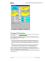
Breakpoint processor (BPP) is an advanced hardware logic circuit designed to help debug the user
programs. It processes output signals of the complex breakpoint triggers and the Tracer Overflow
signal. The entire logic circuit configuration is called the resultant Complex Condition (the Complex
Event). The emulator uses this event to break the emulation after a delay and/or to start/stop the
hardware tracer (when it is in the Forward Tracing or Backward Tracing mode). For more about
controlling the tracer, see the Tracer Control dialog.
You can disable breaking the emulation from BPP (with the Enable Break button). The tracer is
always connected to the Complex Event output.
The breakpoint processor contains:
• two event counters to count complex events identified by the complex breakpoint triggers;
• delay counter to perform the specified delay of the BPP operation (halt of the user program);
• four adjustable logic elements to form the resultant Complex Condition;
• control circuit to start/stop the tracer, when it is in the respective modes.
Counters
The event counters and delay counter are just 16-bit counters and differ only in what they count
(what signal arrives to their input). For the delay counter, these are the machine cycles of the emulation microcontroller. For the event counter, these are the events identified by the complex breakpoint trigger.
One event corresponds to the machine cycle of the emulation microcontroller, during which the
conditions specified for the breakpoint trigger remain true. This means that the event duration is always equal to the duration of the machine cycle, during which the event occurred. Note that the
machine cycle frequency may change.
VERY IMPORTANT: If the specified condition remain true, for example, during 5 consecutive machine cycles, the counter will interpret them as 5 separate (consecutive) events.
The counter works in the decrement mode. It receives the input signal, counts down its initial value
until it equals 1 (for the event counter) or 0 (for the delay counter) and let the received signal
through to its output (outputs the TRUE signal to the rest of BPP). For example, if the event counter
initial value is 1, it will immediately send the input signal through. If the event counter is set to 5, it
will pass the signal at the moment the fifth event occurs after the start of your program.
Adjustable logic elements
Three adjustable logic elements have two configurations to perform either logical OR function, or
AND function. You can toggle the element configuration. In addition to these two configurations, the
fourth adjustable element has two more configurations, when one its input is connected to the output and the other input is not.
On-the-fly access to the breakpoint processor
The PICE breakpoint processor provides on-the-fly access to microcontroller resources. You can
set up and change the break conditions in BPP, while running your program in the real-time mode.
How to control
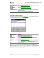
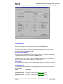
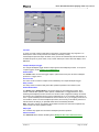
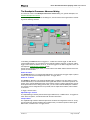
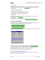
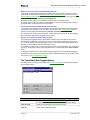
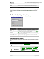
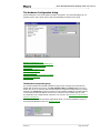
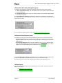
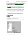
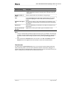
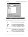
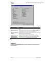
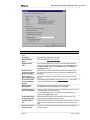
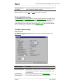
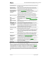
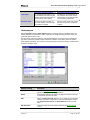
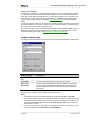
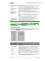
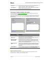
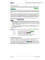
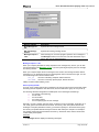
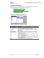
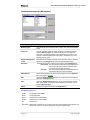
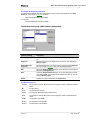
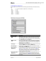
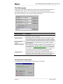
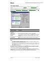
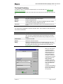
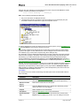
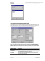
To set up all hardware units, which implement the resultant Complex Condition, use the Breakpoint Processor dialog. You can set up simple and composite conditions to break emulation. Accordingly, there are two versions of the Breakpoint Processor Control dialog.
Hardware Tracer
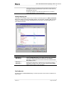
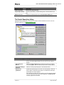
The emulator provides the tracer functions to help you to observe and record the on-chip processes, and also to facilitate interoperation with external measurement instruments (like an oscilloscope or a spectrum analyzer). The tracer can record all the data related to the instructions fetched
by the emulation processor, when it runs your program.
The tracer provides four modes of data recording. The modes differ by the tracer start and stop
conditions used; some of them use the Complex Event from the hardware breakpoint processor.
Version 1.1
Page 34 of 245