1
SmartLink Wireless
TM
User Manual
Software version 2.1X
ii
Welch Allyn SmartLink Wireless
Copyright 2007 Welch Allyn. All rights are reserved. No one is permitted to reproduce or duplicate, in any form, this manual or
any part thereof without permission from Welch Allyn.
Welch Allyn assumes no responsibility for any injury to anyone, or for any illegal or improper use of the product, that may
result from failure to use this product in accordance with the instructions, cautions, warnings, or statement of intended use
published in this manual.
Welch Allyn® and PIC® are registered trademarks of Welch Allyn. SmartLinkTM is a trademark of Welch Allyn. Microsoft®
ActiveSync ® and Windows® are registered trademarks of Microsoft Corporation. .Net is a trademark of Microsoft
Corporation. Pentium® is a registered trademark of Intel Corporation. ARM ® is a regstered trademark of ARM Ltd. Acrobat®
and Reader® are registered trademarks of Adobe Systems Incorporated.
This software is copyright Welch Allyn or its vendors. All rights are reserved. The software is protected by United States of
America copyright laws and international treaty provisions applicable worldwide. Under such laws, the licensee is entitled to
use the copy of the software incorporated with this instrument as intended in the operation of the product in which it is
embedded. The software may not be copied, decompiled, reverse-engineered, disassembled or otherwise reduced to
human-perceivable form. This is not a sale of the software or any copy of the software; all right, title and ownership of the
software remain with Welch Allyn or its vendors.
For information about any Welch Allyn product, call the nearest Welch Allyn representative:
USA 1 800 535 6663
+ 1 315 685 4560
Canada 1 800 561 8797
Australia + 6129 638 3000
800 074 793
China + 86 216 327 9631
European Call Center + 353 46 906 7790
France + 331 6009 3366
Germany + 49 747 792 7186
Japan + 8133 219 0071
Latin America + 1 305 669 9003
Singapore + 656 419 8100
United Kingdom + 44 207 365 6780
Netherlands + 3115 750 5000
South Africa + 2711 777 7555
Sweden + 46 85 853 6551
Caution! Changes or modifications not expressly approved by Welch Allyn could void the purchaser’s authority to operate
the equipment.
Reorder Part Number 001970-E
Manual Part Number 990195 Rev F, 12/2007
Welch Allyn, Inc.
8500 SW Creekside Place
Beaverton, OR 97008-7107 USA
www.welchallyn.com
Printed in USA
Welch Allyn Ltd
Navan Business Park
Dublin Road, Navan
County Meath, Republic of Ireland
iii
Contents
1 - Overview . . . . . . . . . . . . . . . . . . . . . . . . . . . . . . . . . . . . . . . . . . . . . . . 1
System requirements . . . . . . . . . . . . . . . . . . . . . . . . . . . . . . . . . . . . . . . . . . . . . . 3
2 - Installation and upgrade. . . . . . . . . . . . . . . . . . . . . . . . . . . . . . . . . . . 5
3 - Options and setup . . . . . . . . . . . . . . . . . . . . . . . . . . . . . . . . . . . . . . . 15
eSync Sending Station . . . . . . . . . . . . . . . . . . . . . . . . . . . . . . . . . . . . . . . . . . . . 15
4 - Menus, toolbars and screens . . . . . . . . . . . . . . . . . . . . . . . . . . . . . . 19
Menu tree . . . . . . . . . . . . . . . . . . . . . . . . . . . . . . . . . . . . . . . . . . . . . . . . . . . . . .
Toolbars. . . . . . . . . . . . . . . . . . . . . . . . . . . . . . . . . . . . . . . . . . . . . . . . . . . . . . . .
Transmission Event Log window . . . . . . . . . . . . . . . . . . . . . . . . . . . . . . . . . . . .
12-Lead Snapshot window . . . . . . . . . . . . . . . . . . . . . . . . . . . . . . . . . . . . . . . . .
19
25
27
28
5 - eSync Application . . . . . . . . . . . . . . . . . . . . . . . . . . . . . . . . . . . . . . . 31
eSync Application Menus, Toolbars and Screens . . . . . . . . . . . . . . . . . . . . . . . . 31
A - Appendix . . . . . . . . . . . . . . . . . . . . . . . . . . . . . . . . . . . . . . . . . . . . . . 35
Glossary . . . . . . . . . . . . . . . . . . . . . . . . . . . . . . . . . . . . . . . . . . . . . . . . . 37
iv
Contents
Welch Allyn SmartLink Wireless
1
1
Overview
The Welch Allyn SmartLink Wireless system consists of four software components:
•
SmartLink Wireless Monitoring Station (required)
•
eSync Application (required)
•
SmartLink Wireless Gateway Service (optional)
•
SmartLink Wireless Gateway Client (optional)
The SmartLink Wireless Monitoring Station runs on a dedicated computer typically
located within a hospital location accessible to medical personnel (e.g. the Emergency
Department). The primary functions of the system are to receive 12-Lead ECG data
transmitted wirelessly from one or more Welch Allyn PIC 50 units in the field; to display
the 12-Lead data in a standard format; and to route the 12-Lead data to one or more
intended recipients.
The eSync application runs on Pocket PC-based PDAs and handheld devices. eSync is
used to download 12-Lead ECG data from PIC 50 devices and to transmit the 12-Lead
data wirelessly to the hospital receiving station via a cellular network.
The SmartLink Wireless Gateway Service typically runs on an existing server within a
hospital’s computer center. The primary function of this software is to receive 12-Lead
transmissions from the eSync application via the internet and forward the transmissions
to the monitoring station.
While the monitoring station is capable of receiving transmissions directly, the gateway
can be used to prevent the monitoring station from being exposed directly to the internet.
The gateway can receive transmissions on a well known address and send them to an
internal hospital LAN address. This also allows the monitoring station to be part of the
Electronic Protected Health Information (ePHI) zone.
The SmartLink Wireless Gateway Client can be run on any workstation that has network
access to the gateway service. The client connects to the service and enables
administrative personnel to monitor the current activity of the gateway service. This can
be useful for configuring the system and troubleshooting communications problems that
may arise.
The SmartLink Wireless software provides a real-time list of transmissions received. This
list is referred to as the Transmission Event Log. Each entry of the log displays information
about the transmission such as the sender, transmission status, date and time of the
transmission, and the patient associated with the transmission.
The 12-Lead data associated with a transmission in the Transmission Event Log can be
viewed by double clicking the log entry. The SmartLink Wireless software will display the
12-Lead snapshot on the screen in a 4x3 waveform format. Information such as the
patient data and analysis results (if available) are displayed on the left side of the screen.
2
Overview
Welch Allyn SmartLink Wireless
The main features of the SmartLink Wireless software include:
•
A Transmission Event Log to display real-time incoming transmissions and provide
details about each transmission.
•
Automatic notification to selected personnel via email, text messaging and pager
when a new transmission has been received.
•
A snapshot view of 12-Lead data in a convenient graphical format together with
patient and analysis information.
•
The ability to print the 12-Lead data in graphical format.
•
The ability to manually forward the 12-Lead data to selected personnel.
•
Automatic archival of each transmission received.
•
The ability to retrieve, review and print archived transmissions even after deleting
them from the Transmission Event Log.
User Manual
Overview
3
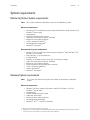
System requirements
Monitoring Station System requirements
Note
This system should be a dedicated system for the Monitoring station.
Minimum requirements
•
•
•
•
•
•
•
•
Windows® NT-class monitoring station computer (Windows® 2000, Windows® XP,
Windows® Server 2003)
x86 processor
50 MB of available hard disk space
Video card and monitor running at 1024x768
Mouse (or similar pointing device)
COM 1 serial port availabilitya
Network/Internet connectionb
Microsoft® ActiveSync®
Recommended system configuration
•
•
•
•
•
•
•
•
•
•
Windows® NT-class receiving station computer (Windows® 2000, Windows® XP,
Windows® Server 2003)
Intel® Pentium® 4 1.0 GHz processor
512 MB of RAM
500 MB+ of available hard disk space (for 12-Lead data storage)
Video card and monitor running at 1024x768
Mouse (or similar pointing device)
Printer connection, local parallel port or network
COM 1 serial port availabilitya
Internet Connectionb
Microsoft® ActiveSync®
Gateway System requirements
Note
This system may be an existing server and does not need to be a dedicated
system.
Minimum requirements
•
•
•
•
•
•
•
a.
b.
Windows ® NT-class computer (Windows® 2000 SP3, Windows ® XP SP2,
Windows ® Server 2003)
x86 processor
5 MB of available hard disk space
Video card and monitor
Mouse (or similar pointing device)
Network/Internet connection
Microsoft® .NETTM 2.0.50727 Framework
Only needed if an external modem will be used for paging.
Depending on your system configuration, the SmartLink Gateway Monitoring Station and Gateway will need a network and/or Internet
connection to receive 12-Lead data and to send email and text message notifications.
4
Overview
Welch Allyn SmartLink Wireless
Recommended system configuration
•
•
•
•
•
•
•
•
Windows® NT-class computer (Windows® 2000 SP3, Windows® XP SP2,
Windows® Server 2003)
Intel® Pentium® 4 1.0 GHz processor
512 MB of RAM
5 MB of available hard disk space
Video card and monitor
Mouse (or similar pointing device)
Internet connection
Microsoft .NET 2.0.50727 Framework
Gateway Client System requirements
Note
The gateway client may be installed on any existing computer which meets the
minimum requirements.It does not need to be a dedicated system.
Minimum requirements
•
•
•
•
•
•
•
Windows® NT-class computer (Windows® 2000 SP3, Windows® XP SP2,
Windows® Server 2003)
x86 processor
1 MB of available hard disk space
Video card and monitor running at 1024x768
Mouse (or similar pointing device)
Network connection with access to the gateway service
Microsoft® .NET® 2.0.50727 Framework
Minimum eSync PDA requirements for transmitting 12-leads
•
•
•
•
•
•
ARM® Processor with Windows® CE 4.2, 4.21, 5.0 for Pocket PC 2000, 2002,
2003
Display size of 240x320
Available serial port
Vendor-specific serial data cable
Internet connection
Microsoft® ActiveSync®
Minimum (Physician) PDA requirements for receiving 12-leads
•
•
•
•
Display size of 240x320
Acrobat® Reader® for Pocket PC
Standard e-mail program, such as Pocket Outlook, to receive 12-lead e-mail
attachments
Internet connection
5
2
Installation and upgrade
The Welch Allyn SmartLink Wireless CD may be used to install or upgrade any or all of the
SmartLink Wireless components: SmartLink Wireless Monitoring Station, SmartLink
Wireless Gateway Service, SmartLink Wireless Gateway Client and the eSync PDA
application. The following sections describe the installation of these components in detail.
Configuration options
SmartLink Wireless components can be configured in several ways depending on the
network configuration and available computers. The possible configurations are:
•
Monitoring station with no gateway
•
Monitoring station and gateway on separate computers
•
Monitoring station and gateway on a single computer
Note
For the latter two configurations, the gateway client may then be installed on any
system that has network access to the gateway. See “Monitoring Station
configuration options” on page 16 for more information.
Connecting a PDA to the SmartLink Wireless Monitoring Station
When installing the SmartLink Wireless Monitoring Station on a system, it is
recommended to connect a PDA for installation of the eSync software. While it is possible
to install ActiveSync and connect a PDA for installation after the SmartLink Wireless
installation, it is recommended to complete this step prior to SmartLink Wireless
installation.
Note
Microsoft ActiveSync should be installed on the PC and handheld computer prior
to installing the SmartLink Wireless software. If ActiveSync is not installed on the
system, it can be downloaded from www.microsoft.com/windowsmobile
To configure the ActiveSync application on the PC
1.
Double click the ActiveSync icon.
2. Select the File menu item then select Connection Settings. This will bring up the
Connection Settings dialog box.
3. Connect the handheld to the PC using a serial cable via a COM port, or via a USB port.
To use a serial cable and COM port:
Select the check box for Allow serial cable or infrared connection to this
COM port.
Click on the combo box below the check box to select an available COM port.
6
Installation and upgrade
Welch Allyn SmartLink Wireless
To use USB:
Click on the check box for Allow USB connection with this desktop
computer.
4. Status Icon: Select Show status icon in the TaskBar.
Click OK.
To connect the handheld to the PC
Note
1.
A cable or docking cradle is needed to connect the handheld to the PC. The cable
or docking cradle must be supplied by the manufacturer of the handheld or its
approved vendor.
Connect the handheld using the cable or docking cradle to the USB port, or to the
COM port (selected in the previous step while configuring the ActiveSync application)
of your PC. This should automatically connect the PC to the handheld via the
ActiveSync application. (Once connected, the round-shaped ActiveSync icon both on
the PC and the handheld should turn green in color).
2. If the connection is not made automatically:
a.
Double click the ActiveSync icon.
b. On the ActiveSync application, select File. Select Get Connected.
c.
If still not connected to the PDA, reset the PDA following the manufacturer’s
instructions for a reset. Typically this is done by inserting the stylus in a small hole
at the bottom of the PDA. After the reset, repeat Step 1 above.
3. Depending on the version of ActiveSync, a “New Partnership” dialog screen may
appear. If so, select Guest Partnership and press Next.
User Manual
Installation and upgrade
7
SmartLink Wireless installation
Upgrading from a previous version
The SmartLink Wireless installation disk can be used to upgrade the SmartLink Wireless
Monitoring Station (previously known as the SmartLink Wireless Server or Receiving
Station) from version 2.0 and higher. It is not necessary to uninstall the previous version.
A backup copy of the system and the SmartLink Wireless installation directory should be
made before proceeding with an upgrade. When the backup is complete, follow the
instructions below and use the same folder as the previous installation for the upgrade of
the Monitoring Station. This will save the current settings as well as the current
transaction log.
Upgrading to the current version of the Monitoring Station will enable it to be used in any
of the configurations described in the previous sections.
Installing SmartLink Wireless
To start the installation and select components
1.
Insert the Welch Allyn SmartLink Wireless CD into the CD drive of the PC.
2. If the installation does not start automatically, start the 'Setup' application by double
clicking on the CD setup icon. This will launch the Setup wizard. Follow the prompts
on the Setup wizard, Setup wizard will display the following pages or screens:
a.
Welcome. click Next.
b. License Agreement. Read the licensing agreement and if you agree, select the
radio button for ‘I accept the agreement.’ Click Next.
c.
Information. Read the pre-install information and click Next.
d. User Information. Enter the User Name and Organization and click Next.
e. Destination Directory. Click Next to install to the default directory or select a
different directory and click Next. The default directory is “C:\Program
Files\Welch Allyn SmartLink Wireless.”
f.
Select Components. Select the components to be installed on the computer.
If Gateway Service or Client is selected, Microsoft .NET 2.0 must be installed on
the system. If .NET is not already installed, select it. If you are not sure, see
“Microsoft .NET 2.0 Framework” on page 8 for more information.
If “SmartLink Wireless Monitoring Station” is selected, the computer will also be
used to install eSync on the PDAs. See “SmartLink Wireless Monitoring Station
installation” on page 8 for more information.
If no components are selected, the installation will proceed to copy just the user
documentation and license agreement.
g. Start Menu Folder. Select the shortcut folder and click Next. The default folder is
“Welch Allyn SmartLink Wireless.”
h. Ready to Install. Review the installation options and click Install.
If installing the SmartLink Wireless Monitoring Station and Microsoft Active Sync
has not been installed or not properly installed on the PC, the application will
8
Installation and upgrade
Welch Allyn SmartLink Wireless
display a failure message. The message will say Microsoft ActiveSync is not
found and inform the user that only the SmartLink Wireless software will be
installed to the PC.
Note
i.
If necessary, download Microsoft ActiveSync from
www.microsoft.com/windowsmobile
The installation will begin and display a progress bar as the SmartLink Wireless
software is copied to your system. Proceed to the following sections, depending
on the component selection(s) made above.
Microsoft .NET 2.0 Framework
If not already on the system, Microsoft .NET 2.0 Framework will need to be installed to
install and run the Gateway Service and Client. For more information on the system
requirements for .Net 2.0, refer to the Microsoft Download Center.
To install .NET 2.0
1.
If .NET is already installed on the system, you will be given the option to Repair or
Uninstall .NET. Press Cancel to cancel the .NET installation, and then confirm by
pressing Yes and Finish. Proceed with the SmartLink Wireless installation.
2. If .NET is not already installed on your system, the .NET setup wizard will guide you
through the .NET installation. Follow the prompts and accept the Microsoft end user
license agreement when appropriate. Once the .NET installation is complete, press
Finish. Continue with the SmartLink Wireless installation.
SmartLink Wireless Monitoring Station installation
Use the Server Configuration dialog to configure SmartLink Wireless monitoring stations
for use with eSync. The settings may be conveniently downloaded to handheld
computers. By storing the settings on PC files, the settings may be downloaded to
multiple handheld computers, eliminating the need to enter them individually on each
handheld.
To configure use with eSync
1.
Create the Server list:
a.
Enter a name in the Server Name edit box. The name must be a text string up to
64 characters in length. The field may not be blank.
b. Enter an address in the Server Address edit box. The address must be a text
string up to 64 characters in length. The address may be in the dotted number
format (e.g., 207.127.96.194) or a text string to denote a hostname (e.g.
wireless.welchallyn.com). The field may not be blank.
c.
Enter an available port number in the Control Port edit box. The control port must
be a number between 1 and 65,535.The field may not be blank. The control port
has the default value 2098.
d. Enter an available port number in the Data Port edit box. The data port must be a
number between 1 and 65,535.The field may not be blank. The data port has the
default value 2099.
e. Press Add to add the Server to the list.
User Manual
Installation and upgrade
f.
9
Repeat the process to add up to 32 servers to the list.
g. Press OK.
ETA/Altitude Entry: You may check the box to turn on the ETA/Altitude feature.
When this option is enabled, the PIC50 users transmitting a 12-Lead will be
required to enter their ETA and Altitude on the PDA each time a 12-lead snapshot
is transmitted.
2. When prompted to install eSync on the handheld, press Yes if ready to install on one
or more handlhelds.
If No is selected, a message is displayed informing that Welch Allyn eSync may be
installed later using the shortcut, Upgrade or Install Welch Allyn eSync. In this case,
only SmartLink Wireless is installed. Skip the following steps and proceed to next
section relevant to your installation configuration.
3. A message box is displayed to prompt the user to connect the handheld to the PC
using ActiveSync. Press OK if the handheld is already connected, or connect the
handheld to the PC and then press OK.
Pending Application Install. If proceeding without connecting the handheld to the PC,
the application will display a message that the SmartLink Wireless eSync application
will be downloaded to the handheld the next time the handheld is connected to the
PC. Only the PC portion of the SmartLink Wireless system (the hospital monitoring
station) is installed.
The next time the handheld is connected to the PC, a message is automatically
displayed asking to install SmartLink Wireless eSync application. Press OK to install
SmartLink Wireless eSync application on the handheld.
4. Add/Remove Programs. This option for Microsoft ActiveSync is automatically
displayed.
5. Retrieving Device Data. This message box is displayed.
6. Installing Applications. Press Yes to install to the default directory on the handheld.
Press No to display a combo box. Select the media location to install.
7.
Application Downloading Complete. Check the handheld screen and press OK.
The handheld will not require any intervention for a typical install. If the program is
already installed, the handheld will wait for user confirmation. Also if the handheld has
Windows Mobile 2003 or later, the message “The program you have installed, may
not display properly because it was designed for a previous version of Windows
Mobile software” may be displayed. There is no known problem for Windows Mobile
2003. This alert may be dismissed. If there is a problem with your version of Windows
Mobile, contact Welch Allyn technical support.
8. The application will prompt to install the eSync application on another handheld. If
installation to another handheld is needed, disconnect the current handheld. Connect
the new handheld to the PC. Press Yes.
If not, select No and the Completing screen of the Setup wizard will be displayed.
10
Installation and upgrade
Welch Allyn SmartLink Wireless
SmartLink Wireless Gateway installation
To install SmartLink Wireless Gateway
Note
1.
If this is the initial installation of SmartLink Wireless Gateway, skip ahead to
Step 2.
If upgrading or re-installing the SmartLink Wireless Gateway after the initial
installation, it may be necessary to stop the service if it is running. This must be done
prior to proceeding with the gateway installation. Administrative privileges are
required to proceed. Access the services tool using “Start|Administrative
Tools|Services.” Alternatively, “Start|Run…” can be used by executing the command
“services.msc /s.” Find and select “SmartLink Gateway Service” and stop it, then
proceed with the installation.When the installation begins, the setup procedure will
uninstall any previous version of the service. The main setup screen will display a
message “Removing previous version of SmartLink Wireless Gateway Service.”
2. SmartLink Wireless Gateway Service Login Configuration. Use this dialog to specify
the account under which the service will automatically login on startup of the system,
or anytime the service is restarted.
a.
Select Login Account. First select the login account from one of the four options:
•
•
•
•
Local Service
Network Service
Local System
This Account
The first three choices are Windows built-in system accounts will not require a
password. If the fourth option is selected, a valid account name and password
must be entered as specified below.
Note
The installation program will not verify the account information. If it is entered
improperly, the installation of the service may fail, or the service may not be able
to start. If this occurs, you can either restart the installation, or manually configure
the username an password of the service from the Service control panel or
Computer Management application.
b. Account Name. Specify the account name in the format “{domain name}\{account
name}.” Even if specifying a account on the local computer, the domain name
must be specified. In this case, either use the computer name or simply “ . “(e.g.
“.\myaccount”).
c.
Password. Enter and confirm the password for the specified account.
3. After completing all the entries, press OK.
4. Service Installation. The main setup screen should display the message “Installing
SmartLink Wireless Gateway Service with automatic startup.” When this is
completed, the installation will proceed automatically to the next step.
5. SmartLink Wireless Gateway Service Configuration. Use this dialog to configure the
SmartLink Wireless Gateway.
6. Enter data for each of the appropriate fields as follows:
a.
Gateway Service IP Address. Enter the IP address that will be used for listening
for connections from eSync on the PDAs. This will be the address that will receive
User Manual
Installation and upgrade
11
connections from the public IP. If a firewall or network gateway with NAT is
present, this will be an internal address that has been set up for port forwarding
on the appropriate ports. If the computer has multiple network adapters, be
certain to select the IP address for the adapter that will receive these forwarded
connections.
b. Gateway Control Port. This is the port the gateway will listen for control
connections from eSync. If NAT is used, this port must be forwarded from the
network access point to the Gateway Service Address.
c.
Gateway Data Port. This is the port the gateway will listen for data connections
from eSync. If NAT is used, this port must be forwarded from the network access
point to the Gateway Service Address.
d. Monitoring Station IP Address. This is the IP address of the SmartLink Wireless
Monitoring Station computer. The Gateway will use this address to connect to the
Monitoring Station.
e. Monitoring Station Control Port. This is the port on which the SmartLink Wireless
Monitoring Station will be configured to listen for control connections. The
Gateway will use this port to connect to the Monitoring Station.
f.
Monitoring Station Data Port. This is the port the SmartLink Wireless Monitoring
Station will be configured to listen for data connections. The Gateway will use
this port to connect to the Monitoring Station.
g. Client Connection Port. This is the port the Gateway will listen for client
connections.The Gateway Client is used to monitor the activity of the Gateway.
h. Client Password. Specify and confirm a password that will be used when
accessing the Gateway from a Client.While it is possible to specify an empty
password, this is not recommended.
i.
7.
Logging Level. Select the logging level. Log entries are written to the Windows
Event Log. Note that “eSync/SLW Communication” entries only take one log
entry for each full communication.
After completing all the entries, press OK.
8. Service Startup. There should be a message saying the SmartLink Wireless Gateway
Service has been started. Press OK.
SmartLink Wireless Gateway Client installation
No additional steps are required for the SmartLink Wireless Gateway Client.When using
the client, it is possible to specify the address, port and password for connection to the
Gateway.
Completing the installation
At the completing prompt, press Finish. This completes the installation and dismisses
Setup wizard from your PC.
eSync Sender List
After the SmartLink Wireless software has been installed and started for the first time,
the first thing that should be done is to set up the Sender List on the hospital monitoring
station. The Sender List is a cross-reference list between PIC50 serial numbers and
12
Installation and upgrade
Welch Allyn SmartLink Wireless
sender names.T he sender name assigned is the name that shows up in the Transmission
Event Log’s Sender column.
To set up the Sender List
1.
Select the Tools menu item from the SmartLink Wireless software menu. Select the
Options submenu item. From the SmartLink Wireless Configuration dialog, select the
Sender List tab.
2. Enter a PIC50 serial number in the PIC Serial Number column and a name to
associate with the PIC50 in the Sender Name column.
3. Repeat the process for all the PIC50s that will transmit to the SmartLink Wireless
software.
Note
Transmissions from any PIC50 that is not entered in the Sender List will display
the PIC50 serial number in the Sender column of the Transmission Event Log.
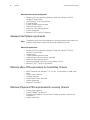
Update or install Welch Allyn eSync
The “update or install” shortcut is installed during the installation of the Welch Allyn
SmartLink Wireless and has two main uses:
1.
Install eSync application on handhelds and
2. Update existing copies of the eSync application on handhelds.
The user may conveniently use this option to update Server Configuration on
handhelds that already have the eSync application installed on them. Upon updating
Servers or adding to the list of Servers this feature may be used to download the list
of Servers to all handhelds.
To update or install eSync
1.
From the Start menu select the ‘Welch Allyn’ | ‘Update or Install Welch Allyn eSync’
shortcut to start the Setup wizard to update or install the eSync application. Follow
the prompts on the Setup wizard, Setup wizard will display the following pages or
screens:
2. Welcome. Click Next.
3. Information. Connect the handheld to your PC (see“To connect the handheld to the
PC” on page 6 for more details). Click Next.
4. Ready to Install. Click Install.
5. Server Configuration. See “SmartLink Wireless Monitoring Station installation” on
page 8 for details.
6. At the prompt to install eSync on the handheld, press Yes.
If No is selected, a message is displayed to inform that Welch Allyn eSync may be
installed later using the shortcut, Upgrade or Install Welch Allyn eSync
7.
A message box is displayed to prompt the user to connect the handheld to the PC
using ActiveSync. Press OK if the handheld is already connected, or connect the
handheld to the PC and then press OK.
User Manual
Installation and upgrade
13
8. Add/Remove Programs. This option for Microsoft ActiveSync is automatically
displayed.
9. Retrieving Device Data. The message box is displayed.
10. Applications Already Installed. If updating an existing eSync application on the
handheld, this message box is displayed. A prompt to reinstall/upgrade the application
is displayed. Press Yes.
11. Installing Applications. Press Yes to install to the default directory on the handheld.
Press No to display a combo box. Select the media location.
12. Application Downloading Complete. Check the handheld screen and press OK.
The handheld will not require any user intervention for a typical install. If the program
is already installed, the handheld will wait for user confirmation. Also if the handheld
has Windows Mobile 2003 or later, the message “The program you have installed,
may not display properly because it was designed for a previous version of Windows
Mobile software” may be displayed. There is no known problem for Windows Mobile
2003. This alert may be dismissed. If there is a problem with your version of Windows
Mobile, contact Welch Allyn technical support.
This completes the install/upgrade on the current handheld.
13. The application will prompt to install the eSync application on another handheld. If
installation to another handheld is needed, disconnect the current handheld. Connect
the new handheld to your PC.Press Yes.
If not, select No and the Completing screen of the Setup wizard will be displayed.
14. Completing. Press Finish. This completes the installation/upgrade to handhelds and
dismisses Setup wizard from your PC.
Removing SmartLink Wireless
Note
If .NET was installed as part of the SmartLink Wireless installation, it will not be
removed using this procedure. To remove .NET, it will need to be necessary to run
Add/Remove Programs and remove it separately.
To uninstall Welch Allyn SmartLink Wireless
1.
Bring up the PC’s Add/Remove Programs.
2. Select ‘Welch Allyn SmartLink Wireless 2.10.’ Press Change/Remove.
3. A prompt is displayed to confirm the removal. Press Yes.
4. A message is displayed to inform the user that any installed SmartLink Wireless
programs were successfully uninstalled. Press OK.
Removing the eSync application from PDAs
To uninstall the eSync application from the handheld
1.
Bring up Microsoft ActiveSync on the PC by double clicking the ActiveSync icon.
2. On ActiveSync, press Tools then press the Add/Remove Programs sub-menu item.
This will bring up ActiveSync’s Add/Remove Programs dialog.
14
Installation and upgrade
Welch Allyn SmartLink Wireless
3. Clear the check box for Welch Allyn eSync on the Add/Remove Programs dialog.
4. Press Remove on the Add/Remove Programs dialog.
5. The Remove Application prompt is displayed. Press OK.
To remove eSync from a PDA without a PC connection
1.
On the PDA, press Start|Settings
2. Select the System tab
3. Select Remove Programs
4. Select “Welch Allyn eSync” and press Remove
5. On the confirmation dialog press Yes
15
3
Options and setup
eSync Sending Station
Multiple Welch Allyn PIC50 devices will be sending 12-lead data to the monitoring station.
Each PIC50 must have an associated PDA handheld computer for transmission.
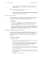
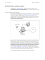
Figure 1: PIC50 eSync Transmission Setup
PDA RS-232 cable
eSync
Program
PIC50
Version X3 or greater
PDA with cellular
connection
Optional gender changer
(male to male)
As seen in “Figure 1: PIC50 eSync Transmission Setup”, an eSync installation requires a
Welch Allyn PIC50 to be connected to an approved handheld computer using the serial
cable supplied by the handheld manufacturer. See “Minimum eSync PDA requirements
for transmitting 12-leads” on page 4 for approved handheld computers and auxiliaries.
Note that some handheld computers/auxiliaries may require a RS232 male-to-male
gender changer to connect to the PIC50. As explained in section 3, the eSync application
is loaded onto the handheld computer during the installation process.
16
Options and setup
Welch Allyn SmartLink Wireless
Monitoring Station configuration options
As mentioned in “Configuration options” on page 5, there are various options for
configuring the SmartLink Wireless components which will receive 12-lead transmissions.
This section describes the possible configurations.
Monitoring Station without Gateway
The SmartLink Wireless Monitoring Station may be installed and run without the use of
the SmartLink Wireless Gateway (see “Figure 2: Monitor station without Gateway”). This
is the typical installation configuration prior to version 2.10 of the system. In this
configuration the system will be a dedicated computer typically located in the ED on an
isolated network such as a dedicated high speed internet connection or in the DMZ.
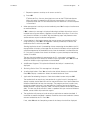
Figure 2: Monitor station without Gateway
Modem for paging
Printer
Internet
SmartLink Wireless
Monitoring Station
Both the SmartLink Wireless Monitoring Station software and the eSync application are
connected to the Internet. The PC running the monitoring station software requires a
fixed IP address and two port assignments. This fixed IP address must be accessible to
eSync on PDAs as a public address on the internet or through a VPN. If network address
translation (NAT) is used the address may be assigned to a router rather than directly to
the monitoring station. This is the same IP address that is then entered in the Server
Address field when adding the Server to the eSync application’s Server list (see
“SmartLink Wireless Monitoring Station installation” on page 8). When installing the
SmartLink Wireless software, ensure that the IP address and ports are not blocked by any
firewall. Contact your Network Administrator concerning this subject.
In this configuration, the gateway and gateway client will not be installed.
User Manual
Options and setup
17
Monitoring Station and Gateway on separate computers
In this configuration, the Gateway is installed on a computer which is typically located in
the network’s DMZ. It may be a dedicated system, but this is not required. More likely it
will be installed on an existing server. The Gateway will run as a windows service.
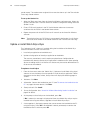
Figure 3: Monitoring station and Gateway on separate computers
Internet
Workstation with
Gateway client
Server with
Gateway service
Printer
Laptop with
Gateway client
SmartLink Wireless
monitoring station
Modem for
paging
To receive 12-lead data from the eSync PDAs, the gateway requires a fixed IP address and
two port assignments. This fixed IP address must be accessible to eSync on PDAs as a
public address on the internet or through a VPN. If network address translation (NAT) is
used the address may be assigned to a router rather than directly to the gateway. This is
the same IP address that is then entered in the Server Address field when adding the
Server to the eSync application’s Server list (see “SmartLink Wireless Monitoring Station
installation” on page 8). When installing the SmartLink Wireless software, ensure that the
IP address and ports are not blocked by any firewall. Contact your Network Administrator
concerning this subject.
The monitoring station will be installed on a system which may be on the local intranet in
the hospital’s Protected Health Information (PHI) zone. This system will be a dedicated
18
Options and setup
Welch Allyn SmartLink Wireless
computer typically located in the ED. It will listen on two internal ports for connections
from the Gateway.
The Gateway Client may be installed on multiple computers such as the Gateway server
and any other computers on the network that have access to the Gateway server.
Monitoring Station and Gateway on a single computer
While this will not be a typical installation, it is possible to install the Monitoring Station
and Gateway on the same computer. This offers no advantage for network isolation, but it
does enable the Gateway Client to be used to monitor network transmissions.
Figure 4: Monitoring station and Gateway on a single computer
Internet
Printer
Workstation for
Gateway client
SmartLink Wireless
Monitoring Station
and Gateway
Modem for paging
In this configuration, the system will be a dedicated computer typically located in the ED
on an isolated network such as a dedicated high speed internet connection or in the DMZ.
The Gateway will run as a windows service. To receive 12-lead data from the PDAs the
gateway requires a fixed IP address and two port assignments. This fixed IP address must
be accessible to eSync on PDAs as a public address on the internet or through a VPN. If
network address translation (NAT) is used the address may be assigned to a router rather
than directly to the gateway. This is the same IP address that is then entered in the Server
Address field when adding the Server to the eSync application’s Server list (see
“SmartLink Wireless Monitoring Station installation” on page 8). When installing the
SmartLink Wireless software, ensure that the IP address and ports are not blocked by any
firewall. Contact your Network Administrator concerning this subject.
The Gateway Client may be installed on multiple computers such the Gateway/Monitoring
Station system and any other computers on that have access to the Gateway.
19
4
Menus, toolbars and screens
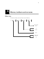
Menu tree
The SmartLink Wireless menu tree consists of the following:
File
Tools
Window
Help
About SmartLink
Wireless
Tile
Cascade
Options
Open 12 Lead
Transmission
Exit
20
Menus, toolbars and screens
Welch Allyn SmartLink Wireless
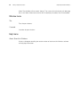
File menu
Open 12-Lead Transmission
The Open 12-Lead Transmission menu option is used to open a previously received
SmartLink Wireless data file with the .slw file extension.
The files are stored as shown below:
SmartLink Wireless
software folder
eSync
Directories
Sender name or
PIC serial number
12-Lead files
File name .slw
Exit
Selecting Exit shuts down the SmartLink Wireless software.
Tools menu
Options
The Options menu item displays the SmartLink Wireless Configuration dialog, from which
it is possible to configure mail settings, forwarding options, automation features, sounds,
and more.
Figure 5: IP addresses
Internet
PDA RS-232 cable
Wireless transmission
PIC50 version
X3 or greater
PDA
PDA IP address determined
by cellular provider
Cell tower
wireless provider
PC SmartLink Wireless
monitoring station or
Gateway
Data port
Monitoring
station or
Gateway IP
Must be a static
Control port
IP address
As seen in “Figure 5: IP addresses”, the SmartLink Wireless software is required to have
a fixed IP address assigned to it. Contact your network administrator concerning the
assignment of the IP address. Your network administrator should assign the IP port
address for the SmartLink Wireless software to ensure that it does not conflict with any
User Manual
Menus, toolbars and screens
21
firewall blocking mechanisms. Use the Configure Transmission Settings dialog to enter
the assigned port address for the SmartLink Wireless software IP address.
Mail Server
The Mail Server tab is used to configure an outgoing SMTP mail server for use with
SmartLink Wireless. Using the appropriate settings for the mail server, provide the server
address and port, as well as the user name and password (if required). If the mail server
requires authentication, make sure to check the checkbox for “My outgoing mail server
requires authentication.” The Test Server Settings button is used to send a test mail
message to verify that the settings are correct. The “results” dropdown list displays the
actual communication with the mail server, for troubleshooting.
Mail Message
The SmartLink Wireless software can be configured to automatically send out e-mail
messages when a 12-lead transmission is received by the receiving station. Use the Mail
Message tab to configure the contents of the mail message sent. Typically the “Sender
Address” will match the “User Name” on the Mail Server tab.
Groups
The Groups tab is used to configure groups for forwarding and paging purposes. A group
is defined as one or more recipients to which a given e-mail message, text message and/
or numeric page is destined. Enter each group name, one per line, using the Groups tab.
When medics use the PIC50 to send a transmission, they will select from one of 16
Group ID’s configured on the PIC50. As the transmission is received, the Group ID will be
matched to the list of Groups configured in this list on the monitoring station. When a
match is found, that group will be used for any auto-forwarding, text messaging or paging
options that have been configured. The match between the PIC50 Group ID and the
monitoring station group is not case sensitive.
Note that if a group name is modified, the system will process this as a delete of the old
name and an add of a new name. All associations for the old name will be removed, and
the new name will have no associations. Also, all PICs will have to be modified to use the
new name. As such, the best practice for changing a name is to use the following steps:
1.
Add the new group name
2. Copy all associations from the Forwarding, Paging and Text Messaging tabs from the
old name to the new name using cut and paste.
3. Start the process of changing all the names on the PICs
4. When all PICs have been modified with the new name, delete the old name.
Since the PICs are most likely distributed throughout the area, the process of modifying
the group names on the PICs may require a number of days. This procedure will allow all
PICs to continue working properly during the transition. If the affected group list is
modified before the transition is complete, be sure to apply the changes to both the old
and new groups.
22
Menus, toolbars and screens
Welch Allyn SmartLink Wireless
Forwarding
The Forwarding tab is used to configure e-mail addresses of group members. Using the
Group dropdown list, select from the configured group names. For each group name,
enter one or more e-mail addresses, one per line, in the space below. Repeat this for each
group name. To temporarily suspend forwarding the 12-lead to specific email recipients
without removing them from the list, place a dash (“-“) in front of the addresses. To
associate a name with the email address, use the following syntax:
“Name” <[email protected]>
For example:
“Dr. Smith” <[email protected]>
Make sure this syntax will work with the email server before entering all addresses in this
format.
Paging
The Paging tab is used to configure numeric pager numbers of group members. Using the
Group dropdown list, select from the configured group names. For each group name,
enter one or more dialing sequences, one per line, in the space below. This dialing
sequence will typically be a phone number followed by a series of characters and
numbers for making paging selections and displaying a page message. This sequence will
depend on the paging service dialed and the dialing device in use. Most standard
modems use a comma for creating a pause, which may be needed as part of the dialing
sequence.
Repeat this for each group name. The Dialing Device dropdown list contains one or more
detected dialing devices (such as modems) attached to the receiving station. Select the
appropriate dialing device to be used to dial numeric pages.
Text Messaging
The Text Messaging tab is used to configure mobile number-based e-mail addresses of
group members for SMS text messaging. Using the Group dropdown list, select from the
configured group names. For each group name, enter one or more e-mail addresses, one
per line, in the space below. Repeat this for each group name. The “New” button provides
a facility for converting the mobile number into the appropriate e-mail address based on
your wireless provider. Your actual e-mail address may vary based on your mobile carrier.
Consult your mobile carrier for specific information and for details on potential costs
associated with sending SMS text messages. To temporarily suspend forwarding the 12lead to specific text message recipients without removing them from the list, place a
dash (“-“) in front of the addresses. To associate a name with the email address use the
following syntax:
“Name” <[email protected]>
For example:
“Dr. Smith” <[email protected]>
Make sure this syntax will work with the email server before entering all text message
numbers in this format.
User Manual
Menus, toolbars and screens
23
TCP/IP
The TCP/IP tab is used to configure the ports used by the SmartLink Wireless software
used to communicate with the eSync application. The default port values are 2098 and
2099, but these values may be changed if needed. See “Figure 5: IP addresses” on
page 20, and contact your network administrator for more information concerning port
configuration.
Sender List
The Sender List dialog is used to assign a “Sender” name to a PIC50 serial number. On
receiving a transmission, the Server displays the sender name in the Sender column of
the Transmission Event Log. If the SmartLink Wireless software receives a transmission
from a PIC50 that is not in the list, the PIC50 serial number will show up in the Sender
column of the Transmission Event Log. Note that the sender name is the name of the
folder in which 12-Lead Data Files and any corresponding PDF files are archived (see
“Open 12-Lead Transmission” on page 20.)
Event Log
The Event Log tab is used to select which columns of the Transmission Event Log
window are displayed. By default, all columns are displayed; the “Trns #” column,
however, may not be hidden.
Sounds
The Sounds tab is used to configure audible notifications played when 12-lead
transmissions are received. A .WAV file can be selected using the Browse button. The
frequency selection for the Audio Notification determines the period at which the
notification will sound. The audio alarm is turned off automatically at user interaction, such
as when the mouse is moved.
Automated Features
The Automated Features tab is used to enable or disable the various actions which can
take place automatically when a 12-lead transmission is received. These settings can be
used to:
•
Automatically open 12-lead snapshots for viewing
•
Automatically print 12-lead snapshots to a specified printer
•
Automatically create 12-lead PDF files and optionally forward them via email as
configured in the Forwarding tab
•
Automatically dial pager numbers as configured in the Paging tab
•
Automatically send text messages as configured in the Text Messaging tab.
Debug
This tab enables the site to turn on debug logging to assist in diagnosing system
problems. By default, debug logging is turned off. To turn it on, check the “Debug On”
check box. This will keep one log file for each day containing information about the
reception and processing of 12-lead transmissions. This information can be used by the
site and Welch Allyn support to detect system failures. Optionally, the log files can be
saved on error conditions only. These files will be saved in a sub-folder of the installation
24
Menus, toolbars and screens
Welch Allyn SmartLink Wireless
folder. The subfolder will be named “debug.” The system will maintain only 20 debug log
files in this folder. When more than 20 files are detected, the oldest files will be deleted.
Window menu
Tile
Tiles all open windows.
Cascade
Cascades all open windows.
Help menu
About SmartLink Wireless
Displays a dialog box detailing the version number of the SmartLink Wireless software
and copyright information.
User Manual
Menus, toolbars and screens
25
Toolbars
Each of the SmartLink Wireless Monitoring Station windows has a toolbar that can be
used to execute commands. The tool bar buttons will change based on the window
currently displayed.
Main window toolbar buttons
Open 12-Lead
For more details, see “Open 12-Lead Transmission” on page 20.
12-Lead Snapshot window toolbar buttons
Print Preview
Print preview is used to view the 12-Lead data as it will appear when printed. The preview
can also be zoomed.
Print
Sends the currently selected 12-lead snapshot to the printer.
Save 12-lead As
This option is used to save the selected open 12-lead file to a different file name or
location. When the save is complete, the current 12-lead file will still be displayed.
Close Window
Closes the currently selected 12-lead snapshot window. If an associated print preview
window is open for this snapshot, it will also be closed.
Forward 12-Lead
This option can be used to manually forward a PDF of the currently selected 12-lead
snapshot to a specified list of email recipients. When the button is clicked, a “Forward 12
Lead” sub-window is opened for the currently selected snapshot.
This window will display the list of the Groups that have been configured in the “Tools |
Options” Groups tab. When a group is selected, the Group Members which have been
configured in the Forwarding tab for that group will be displayed. To forward the 12-lead to
all member of the group, click the “Forward to Group” button or just double click the
group. To forward the 12-lead to selected members of the group, select one or more
members, and click the “Forward to Member(s)” button or just double click the group
member. To select multiple members, press and hold the “Ctrl” button on the keyboard
while selecting.
To forward the 12-lead to an email address that has not already been configured in the
Forwarding tab, enter that address in the “email Address” text box and click the “Forward
to Specified Address” button.
All email addresses selected for forwarding will be listed in the “Forwarding Recipients
List.” If addresses need to be removed from the list, use the “Remove” button to remove
26
Menus, toolbars and screens
Welch Allyn SmartLink Wireless
selected addresses from the list, or the “Clear” button to remove all addresses. When
the list contains all the email addresses to which this 12-lead will be forwarded, click the
“Send” button. This will start the process of emailing the 12-lead. Monitor the
“Forwarding Recipient List” to view the status of the send. When complete, click the
“Done” button to close the window, or the “Clear” button to start a new list.
Note
If an attempt is made to close the 12-lead snapshot while the send is in progress
a warning will be displayed that proceeding to close the window may abort the
send.
If the process of sending or building the recipients list is interrupted by the receipt of a
new 12-lead transmission, the current state of the 12-lead forwarding will remain for
completion after the new 12-lead operation is complete.
Print Preview window toolbar buttons
Zoom
Zoom allows the 12-Lead snapshot print preview to be magnified. The Zoom feature does
not change the appearance of the print out.
Print
Sends the previewed 12-Lead snapshot to the printer.
Close Window
Closes the Print Preview window.
User Manual
Menus, toolbars and screens
27
Transmission Event Log window
When the SmartLink Wireless software is started, the Transmission Event Log is displayed
maximized. Note the Transmission Event Log remains on the screen as long as the Server
is running. The log window may be resized or minimized but may not be closed.
The Transmission Event Log provides a detailed listing of 12-Lead transmissions received.
When the SmartLink Wireless software receives a valid transmission, it is added to the
Transmission Event Log. Depending on the options selected by the user, a sound may be
played on the PC running the SmartLink Wireless software and an email, text message
and/or page may be sent out automatically by the Server to designated personnel
notifying them of a new transmission.
After the transmission is added to the Transmission Event Log, all currently known data
about the transmission (such as transmission number, sender name, status of the
transmission, current progress, elapsed time of the given transmission, and the date and
time the transmission was accepted) are added to the log entry.
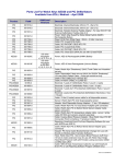
Table 1: Transmission Event Log fields
Column
Trns #
Viewed?/First Viewed
Sender
Status
Progress
Transfer Time
Recv Date
Recv Time
Group
Acq Date
Acq Time
12-Lead ID
Patient ID
Patient Name
Unit ID/Phone #
Dept
Description
Transmission number. A sequential index in time that the transmission was received relative to
all transmissions currently existing in the Transmission Event Log. This field is for reference
purposes only. If a transmission is deleted from the Log, the transmissions following the
deleted transmission are updated -- each transmission number is decremented by one.
Whether the given 12-Lead has been opened/viewed. When a transmission is accepted, the
field displays “No.” After the transmission is successfully completed and the Transmission is
opened for the first time the entry for this field is changed from “No” to “Yes – date / time,”
indicating the date and time the 12-Lead data was first opened for viewing. Note that only
successful, “Complete” 12-Lead transmissions may be viewed. Failed and cancelled
transmissions will always display “No.”
Name from the Sender List dialog. See “Sender List” on page 23 for more details.
Indicates the status of a given transmission. Possible values are as follows:
• Complete: The transmission was completed successfully.
• Failed: The transmission failed prematurely (due to factors such as excessive network
traffic, timing out, a dropped connection, etc.)
• Re-transmitting: The transmission is not yet complete and the SmartLink Wireless
software is attempting to request retransmission of needed data.
• Sender Cancelled: The sender explicitly cancelled the transmission via the Welch Allyn
PIC50 while the SmartLink Wireless software was waiting for the original transmission to
complete.
Note that only “Complete” 12-Lead transmissions can be opened and viewed. Also, if a
transmission fails or the sender cancels, the Hospital, Acq Date, Acq Time, Patient ID, Patient
Name, Unit ID, and Dept fields will remain blank because the transmission data is incomplete.
Progress of a given transmission in terms of percentage complete.
Elapsed time for a given transmission. When a 12-Lead transmission is accepted, the Transfer
Time column for the log entry begins at “00:00” and increases as data is transferred. When the
transmission is complete, the counter for the given transmission is stopped, and the transfer
time displayed reflects the amount of time the transmission took from start to finish.
Date a given transmission was accepted by the SmartLink Wireless software.
Time a given transmission was accepted by the SmartLink Wireless software.
The group name/ID selected from the PIC50 device.
Date the patient was created by the Welch Allyn PIC50.
Time the patient was created by the Welch Allyn PIC50.
Unique identifier of the transmission.
ID of the patient associated with the 12-Lead data.
Name of the patient associated with the 12-Lead data.
Unit ID of the Welch Allyn PIC50 used to acquire the 12-Lead data. This may also be entered as
the phone number of the emergency personnel that acquired the 12-lead as a quick reference
for the hospital personnel.
Department assigned to the Welch Allyn PIC50 used to acquire the 12-Lead data.
28
Menus, toolbars and screens
Welch Allyn SmartLink Wireless
Clearing Transmission Entries from the Transmission Event Log
Right clicking an entry of the Transmission Event Log displays a pop-up menu with three
items “Clear Selected Item,” “Clear All Failed and Cancelled Items”, and “Clear All Items.”
12-Lead Snapshot window
The SmartLink Wireless software allows 12-Lead data, patient information, and analysis
results (if available) to be viewed conveniently from one window. A transmission may be
opened in one of the following ways:
•
Double clicking a successfully completed entry in the Transmission Event Log.
•
Pressing the “Open 12-Lead” toolbar button, see “Open 12-Lead Transmission”
on page 20 for details.
•
Selecting the “File” menu item and then the “Open 12-Lead Transmission,” see
“Open 12-Lead Transmission” on page 20 for details.
•
A new transmission may automatically be opened due to options selected by the
user, see “Event Log” on page 23 for details.
When a 12-Lead Snapshot is opened, the left pane of the window displays date and time,
patient information, and if available, analysis data and interpretive results. Table 2 lists the
information that is displayed.
Table 2: 12-Lead Snapshot fields
Displayed data Description
ETA
Estimated Time of Arrival supplied by the medic. This is only available if the “Eta/Altitude Entry”
option had been turned on when eSync was installed on the PDA.
Altitude
Altitude supplied by the medic. This is only available if the “Eta/Altitude Entry” option had been
turned on when eSync was installed on the PDA.
12-Lead ID
Same as “12-Lead ID” on the Transmission Event Log
Patient ID
Same as “Patient ID” on the Transmission Event Log
Name
Same as “Patient Name” on the Transmission Event Log
Date
Same as “Acq Date” on the Transmission Event Log
Time
Same as “Acq Time” on the Transmission Event Log
Age
Patient’s Age
Sex
Patient’s Sex
S/N
PIC50 Serial Number
Dept
Same as “Dept” on the Transmission Event Log
Unit/Phone #
Same as “Unit ID” on the Transmission Event Log
Group
The Group ID selected on the PIC50 when the 12-lead was transmitted to the monitoring station.
Heart Rate
As measured by the PIC50 when the snapshot was taken. This is only available if an automatic or
manual analysis of the snapshot was performed on the PIC50.
PR Interval
As measured by the PIC50 when the snapshot was taken. This is only available if an automatic or
manual analysis of the snapshot was performed on the PIC50.
QRS Duration
As measured by the PIC50 when the snapshot was taken. This is only available if an automatic or
manual analysis of the snapshot was performed on the PIC50.
QTC Interval
As measured by the PIC50 when the snapshot was taken. This is only available if an automatic or
manual analysis of the snapshot was performed on the PIC50.
P Axis
As measured by the PIC50 when the snapshot was taken. This is only available if an automatic or
manual analysis of the snapshot was performed on the PIC50.
QRS Axis
As measured by the PIC50 when the snapshot was taken. This is only available if an automatic or
manual analysis of the snapshot was performed on the PIC50.
T Axis
As measured by the PIC50 when the snapshot was taken. This is only available if an automatic or
manual analysis of the snapshot was performed on the PIC50.
Analysis
Analysis from the PIC50 if an automatic or manual analysis of the snapshot was performed on the
PIC50.
User Manual
Menus, toolbars and screens
29
The major portion of the window displays the 12-Lead snapshot of ECG waveform data, in
the conventional 4x3 layout, in which each 12-Lead is a 2.5-second strip, and a full 10second strip of lead II below it. Using the horizontal scroll bar on the 12-Lead Snapshot
window it is possible to pan across all available ECG waveform data for a complete
review.
Note
The SmartLink Wireless software allows the user to open multiple 12-Lead
Snapshot windows simultaneously for ease of comparison and viewing.
30
Menus, toolbars and screens
Welch Allyn SmartLink Wireless
31
5
eSync Application
The Welch Allyn eSync application runs on a handheld computer. To receive data from a
PIC50 device the handheld must be connected via serial cable to the PIC50. When a
transmission is sent from a PIC50 device, the eSync application receives the transmission
and sends it wirelessly over the Internet to the SmartLink Wireless software running on a
PC.
Note
The blue, underlined text links may be clicked to obtain help or information on a
topic or feature of the eSync application.
eSync Application menus, toolbars and screens
Tools menu
When transmitting 12-lead data from a PIC50 using the eSync software on a PDA, the
best practice is to first power on the PIC50, then connect the PDA to the PIC50 using the
serial cable before starting the eSync software. This enables the software to detect the
presence of the COM1 serial port on the PDA. In some case, if the COM1 port cannot be
detected or another port has been configured for use, the next available port (typically
COM2) may be initialized. This may result in some PDAs not being able to establish a
cellular internet connection, or in the loss of an existing connection.
Serial Port settings
This dialog allows the user to select a serial port for communicating with the PIC50. The
dialog displays a combo box labeled Serial Port with a drop down list of available serial
ports. The user may click on the combo box arrow to see the list of available serial ports to
select any port from the list. To enable the PDA to detect the presence of the COM1 serial
port, the best practice is to connect the serial cable to the PIC before starting the eSync
software and attempting to configure the serial port.
This dialog also allows the user to select a baud rate for communicating with the PIC50.
The dialog displays a Baud Rate combo box with a drop down list of available baud rates.
The user may click on the arrow to see the list of available baud rates and select any baud
rate from the list.
The Refresh button updates the list of currently available serial ports and baud rates.
Unless directed otherwise by Welch Allyn SmartLink Wireless support, the serial port
settings should always be configured to use Serial Port COM1 and a Baud Rate of 57600.
32
eSync Application
Welch Allyn SmartLink Wireless
Server Configuration
The Server Configuration dialog allows the user to add, delete, and update SmartLink
Wireless servers to which the eSync application may send out transmissions. The dialog
also offers the option to automatically connect to the Internet on application startup.
Add, Delete, and Update:
The Server Configuration dialog provides the user the capability to build a list of SmartLink
Wireless servers. A maximum of thirty-two Servers may be added to the list. The user
may add a new Server by entering Server Name, Server Address, Data Port, and Control
Port in the appropriate edit boxes. See “SmartLink Wireless Monitoring Station
installation” on page 8 for details on the data to enter in the edit boxes. Upon entering all
the information, the user may press the Add button to add the new Server to the list.
Even if the Server list is created first on the PC, the user may later further modify the list
at the handheld by using the Server Configuration dialog.
The user may press the Delete button to delete a selected Server from the list.
The user may update a Server by selecting the Server on the list, editing its fields using
the combo boxes, and pressing the Update button.
Auto Connect on Startup:
When this option is checked the eSync application will automatically try to establish an
Internet connection on startup. Otherwise an Internet connection must be established
manually prior to sending 12-Lead data to SmartLink Wireless software.
Test SmartLink Wireless software
The dialog displays a list of the SmartLink Wireless servers that are available. The user
may select any Server on the list and press the Begin Transmission button to send a ‘test’
transmission to the Server. A message is displayed to the user notifying success or failure
of the test. In case of failure, the reason for failure is indicated.
Help menu
About Welch Allyn eSync
Displays a dialog box detailing the version number of the product and copyright
information.
User Manual
eSync Application
33
eSync application states
When not transmitting data, the eSync application monitors the serial port for incoming
data from a PIC50. The main screen of the eSync application displays:
Initializing (and shows the selected serial port and baud rate)
Waiting for device transmission...
As the eSync application starts receiving data from PIC50 it indicates to the user it is
processing data:
Processing incoming data...
At this stage, if the eSync application does not receive data from the PIC50 for two
seconds, it terminates the transmission and goes back to the state waiting for device
transmission.
When all data for a particular transmission has been received from PIC50, the eSync
application displays its list of Servers and prompts the user to select a Server from the
list.
Note that if there is only one Server, the eSync application does not display the Server list
to the user. The eSync application automatically sends out the transmission to the Server
without waiting for any user interaction.
After the user selects a Server from the list and presses the Begin Transmission button,
the main screen of the eSync Application indicates the following stages:
Connecting to 12-Lead Server...
Transmitting data to 12-Lead Server...
Waiting for delivery confirmation...
If the eSync application is unable to connect to the selected Server, it displays a message
to the user and indicates a reason for not being able to connect. At this point, the user is
given the choice to press the Cancel button to abort the transmission or he may press OK,
located at the top left corner of the screen, to continue trying to establish a connection
with the Server.
On successfully sending out the transmission to the Server, the eSync application
displays a success message and goes back to the state waiting for device transmission.
If the transmission to the Server fails, the eSync application displays a failure message
and indicates a reason for the failure. A transmission may fail for several reasons, such as,
inability to connect to the Internet, incorrect Server configuration (e.g. wrong IP address),
Server not up and running, etc.
34
eSync Application
Welch Allyn SmartLink Wireless
35
A
Appendix
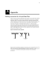
Naming convention for 12-Lead Data Files
When the SmartLink Wireless Monitoring Station receives a transmission from a Sending
Station, the associated 12-Lead Data File is automatically saved on the PC running the
monitoring station. The file is saved under the directory where the SmartLink Wireless
software is installed. If the original 12-Lead Data File is removed or renamed the file
cannot be opened from the Transmission Event Log by double clicking the log entry. The
file may still be opened by using the File | Open 12-Lead Transmission (section 5.1.1)
menu item or the Open 12-Lead toolbar button (section 5.5.1). Note that when a
transmission is cleared from the Transmission Event Log, the file corresponding to the
transmission does not get deleted. The file remains in its original location and may be
viewed by opening the file from the File | Open 12-Lead Transmission menu item or the
Open 12-Lead toolbar button. The file may also be opened by simply double clicking the
filename on the Windows Explorer.
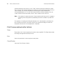
Figure 6: 12-Lead Data File name composition
0102010517081252 - Dept-Unit - 8530297 .slw
Department
and Unit ID
Patient ID
Extension
Unique identifier
for file
Figure 6 details the individual components that make up the 12-Lead Data File name. The
Date, Time, and Serial Number combination constitute the “Patient ID” on the
Transmission Event Log. The unique identifier is used in case the same 12-Lead Data File
is sent twice; it is derived from a running clock contained within the Windows
environment.
36
Appendix
Welch Allyn SmartLink Wireless
37
Glossary
The following definitions, acronyms and abbreviations are defined for the purpose of this
document.
12-Lead Data File A binary file corresponding to a transmission. Contains 12-Lead data,
and analysis results if available. Has a file extension type “slw”
CDMA Code Division Multiple Access
DMZ “Demilitarized Zone”, a part of a site’s network configuration which has direct
exposure to the Internet and buffers access from the Internet to the internal local area
network.
ED Emergency Department
eSync application Same as SmartLink Wireless eSync
Gateway Welch Allyn SmartLink Wireless Gateway Service
Gateway Client Welch Allyn SmartLink Wireless Gateway Client
Monitoring Station Physical location of the SmartLink Wireless Monitoring Station
software
PHI Protected Health Information
PIC50 Portable Intensive Care, Multi Parameter Monitor/Defibrillator
RS-232 A serial communication protocol
Sending Station Physical location where patient 12-Lead data and optional analysis
results are acquired using a Welch Allyn PIC50
SmartLink Wireless Welch Allyn SmartLink Wireless System
SmartLink Wireless eSync application The part of Welch Allyn SmartLink Wireless
System that runs on a handheld computer
SmartLink Wireless software The various components of the Welch Allyn SmartLink
Wireless System that run on a PC
38
Glossary
Welch Allyn SmartLink Wireless