1
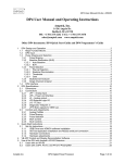
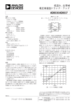
ALL PASSIVE COMPONENTS EXHIBIT
"NON IDEAL" BEHAVIOR
Reprinted from EDN Magazine (January 20, 1994) © CAHNERS PUBLISHING COMPANY 1995, A Division of Reed Publishing USA
COMPONENT
LF BEHAVIOR
HF BEHAVIOR
RESPONSE
Z
WIRE
f
Z
f
CAPACITOR
Z
INDUCTOR
f
Z
RESISTOR
f
a
7.59
A specific case in point is the frequency response of a simple wire compared to that
of a ground plane. In many circuits, wires are used as either power or signal returns,
and there is no ground plane. A wire will behave as a very low resistance (less than
0.02Ω/ft for 22-gauge wire) at low frequencies, but because of its parasitic
inductance of approximately 20nH/inch, it becomes inductive at frequencies above
13kHz. Furthermore, depending on size and routing of the wire and the frequencies
involved, it ultimately becomes a transmission line with an uncontrolled impedance.
From our knowledge of RF, unterminated transmission lines become antennas with
gain. On the other hand, large area ground planes are much more well-behaved, and
maintain a low impedance over a wide range of frequencies. With a good
understanding of the behavior of real components, a strategy can now be developed
to find solutions to most EMI problems.
RADIO FREQUENCY INTERFERENCE
The world is rich in radio transmitters: radio and TV stations, mobile radios,
computers, electric motors, garage door openers, electric jackhammers, and
countless others. All this electrical activity can affect circuit/system performance
and, in extreme cases, may render it inoperable. Regardless of the location and
magnitude of the interference, circuits/systems must have a minimum level of
immunity to radio frequency interference (RFI). The next section will cover two
general means by which RFI can disrupt normal instrument operation: the direct
effects of RFI sensitive analog circuits, and the effects of RFI on shielded cables.
Two terms are typically used in describing the sensitivity of an electronic system to
RF fields. In communications, radio engineers define immunity to be an
instrument’s susceptibility to the applied RFI power density at the unit. In more
general EMI analysis, the electric-field intensity is used to describe RFI stimulus.
48