1
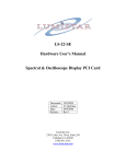
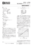
THIRD-ORDER INTERCEPT USING DATA FOR AD831
+24
+10
3RD ORDER INTERCEPT POINT
IP3
1 dB COMPRESSION POINT
1 dB
-10
IF = 10.7 MHz
RF = 100 MHz
LINEAR
OUTPUT
OUTPUT
POWER
(dBm)
3RD ORDER IMD
AT 2f1 - f2 AND 2f2 - f1
-78
INPUT POWER (dBm)
a
3.51
The problem with this metric is that it has meaning only for certain simple cases. In
particular, the 3rd harmonic is assumed to increase at three times the rate of the
fundamental. The appeal of P3OI lies in the fact that it is easily measured, or at
least, it is easy to obtain measurements. (The measurements are not hard to make,
but it will be found that the apparent P3OI is signal-dependent). Apply a low level
signal, at some known level PO (in dBm, see Figure 3.51), measure the output power
at the fundamental, P1 (in relative terms, dBc) and at the third harmonic, P3 (also in
dBc) and from simple geometry calculate
P3OI = PO+ 1/2 (P1–P3)
Eq. 6
The non-linearity in some classical circuits, such as the diode-ring mixer,
approximates a cubic function, and the above relationship holds, but in practice, the
P3OI can be quite misleading, for several reasons. First, other circuits may not, in
general, exhibit this type of non-linearity. This type of behavior could easily lead to
apparent third-order intercept values which were impressively high (theoretically
infinite, if ‘measured’ using signals of less than the critical amplitude).
A spur chart is a compilation of the nf1 ± mf2 products that result from the mixing
process. The spur chart is useful because it allows an engineer developing a
frequency plan for a radio to identify possible problems due to spurious signals
created in the mixer. However, the spur chart is also tedious to create; for n = m = 7,
a chart requires 112 measurements.
The compilation of results is the spur chart (also called a “mixer table”). Details of
making the spur chart measurements and results are given in the AD831 data sheet
(see Reference 17).
50