1
FastTrace 2
FastTrace 2
by Xtralis
Users‟ Manual
Version 2.6 – Release 18 September 2012
Document reference 19532050
2
FastTrace 2
User‟s Manual | General information
General information
Disclaimer
The contents of this document are provided on an "as is" basis. No representation or warranty (either
express or implied) is made as to the completeness, accuracy or reliability of the contents of this document.
The manufacturer reserves the right to change designs or specifications without obligation and without
further notice. Except as otherwise provided, all warranties, express or implied, including without limitation
any implied warranties of merchantability and fitness for a particular purpose are expressly excluded.
Intellectual Property and Copyright
This document includes registered and unregistered trademarks. All trademarks displayed are the
trademarks of their respective owners. Your use of this document does not constitute or create a license or
any other right to use the name and/or trademark and/or label. This document is subject to copyright owned
by Xtralis AG ("Xtralis"). You agree not to copy, communicate to the public, adapt, distribute, transfer, sell,
modify or publish any contents of this document without the express prior written consent of Xtralis.
General Warning
This product must only be installed, configured and used strictly in accordance with the General Terms and
Conditions, Technical and User Manual and product documents available from Xtralis. All proper health and
safety precautions must be taken during the installation, commissioning and maintenance of the product.
The system should not be connected to a power source until all the components have been installed. Proper
safety precautions must be taken during tests and maintenance of the products when these are still
connected to the power source. Failure to do so or tampering with the electronics inside the products can
result in an electric shock causing injury or death and may cause equipment damage. Xtralis is not
responsible and cannot be held accountable for any liability that may arise due to improper use of the
equipment and/or failure to take proper precautions. Only persons trained through an Xtralis accredited
training course can install, test and maintain the system.
Liability
You agree to install, configure and use the products strictly in accordance with the User Manual and product
documents available from Xtralis.
Xtralis is not liable to you or any other person for incidental, indirect, or consequential loss, expense or
damages of any kind including without limitation, loss of business, loss of profits or loss of data arising out of
your use of the products. Without limiting this general disclaimer the following specific warnings and
disclaimers also apply:
Fitness for Purpose
You agree that you have been provided with a reasonable opportunity to appraise the products and have
made your own independent assessment of the fitness or suitability of the products for your purpose. You
acknowledge that you have not relied on any oral or written information, representation or advice given by or
on behalf of Xtralis or its representatives.
Total Liability
To the fullest extent permitted by law that any limitation or exclusion cannot apply the total liability of Xtralis
in relation to the products is limited to:
(i) in the case of services, the cost of having the services supplied again; or
(ii) in the case of goods, the lowest cost of replacing the goods, acquiring equivalent goods or having the
goods repaired.
Indemnification
You agree to fully indemnify and hold Xtralis harmless for any claim, cost, demand or damage (including
legal costs on a full indemnity basis) incurred or which may be incurred arising from your use of the products.
Miscellaneous
If any provision outlined above is found to be invalid or unenforceable by a court of law, such invalidity or
unenforceability will not affect the remainder which will continue in full force and effect. All rights not
expressly granted are reserved.
3
4
FastTrace 2
Document Conventions
The following icons conventions are used in this document.
Convention
Description
Caution: This icon is used to indicate that there is a danger to equipment.
The danger could be loss of data, physical damage, or permanent
corruption of configuration details.
Warning: This icon is used to indicate that there is a danger of electric
shock. This may lead to death or permanent injury.
Warning: This icon is used to indicate that there is a danger of inhaling
dangerous substances. This may lead to death or permanent injury.
Tradename statement
ADPRO is a registered trademark of Xtralis AG Pty Ltd.
Contact Us
The Americas +1 781 740 2223 Asia +852 2916 8876 Australia and New Zealand +61 3 9936 7000
UK and Continental Europe +44 1442 242 330 the Middle East +962 6 588 5622
www.xtralis.com
User‟s Manual | Contents
Contents
General information ........................................................................................................................................... 3
Contents ............................................................................................................................................................ 5
1
Safety instructions ..................................................................................................................................... 7
2
Hardware ................................................................................................................................................... 9
2.1
Technical specifications ................................................................................................................... 11
2.2
Front LED indicators ........................................................................................................................ 12
3
Client Setup and Configuration ................................................................................................................ 13
3.1
Initial configuration ........................................................................................................................... 13
3.1.1
Launching the FastTrace 2 client in Internet Explorer ............................................................. 13
3.1.2
Launching the FastTrace 2 client in its own window ............................................................... 14
3.1.3
Adding a FastTrace 2 server to the FastTrace 2 client............................................................ 16
3.1.4
Setting date and time ............................................................................................................... 18
4
Users........................................................................................................................................................ 19
4.1
Default users .................................................................................................................................... 20
4.2
Adding new users ............................................................................................................................ 21
4.2.1
Strong passwords .................................................................................................................... 22
4.2.2
User rights ................................................................................................................................ 23
4.3
Modifying an existing user ............................................................................................................... 25
4.4
Granting the technician .................................................................................................................... 26
5
Using IP cameras .................................................................................................................................... 27
5.1
IP camera setup ............................................................................................................................... 27
6
Using analogue cameras ......................................................................................................................... 33
6.1
Camera Configuration ...................................................................................................................... 33
6.2
Camera URLs .................................................................................................................................. 37
7
Video monitor ........................................................................................................................................... 39
7.1
Connection ....................................................................................................................................... 39
7.2
Configuration ................................................................................................................................... 39
7.3
Resolution ........................................................................................................................................ 40
8
Alarms ...................................................................................................................................................... 41
8.1
Arming/Disarming the video system ................................................................................................ 41
8.1.1
Arm/Disarm schedule .............................................................................................................. 42
8.1.2
Arm/Disarm Switch .................................................................................................................. 43
8.2
Email address book ......................................................................................................................... 44
9
Operational mode .................................................................................................................................... 47
9.1
Operational mode with manual selection ......................................................................................... 47
9.2
Operational mode with time schedule ............................................................................................. 48
10
Configuration ....................................................................................................................................... 49
10.1 Storing a configuration ..................................................................................................................... 49
10.2 Activating a configuration ................................................................................................................. 50
11
Watching live images ........................................................................................................................... 51
11.1 Tools ................................................................................................................................................ 55
11.1.1
Info display ............................................................................................................................... 55
11.1.2
Taking a snapshot ................................................................................................................... 56
11.1.3
Local video recordings ............................................................................................................. 58
11.1.4
Audio ........................................................................................................................................ 58
11.2 PTZ control ...................................................................................................................................... 59
12
Recording............................................................................................................................................. 61
12.1 Continuous recording ....................................................................................................................... 61
12.2 Recording on event .......................................................................................................................... 64
12.3 Adding holidays ............................................................................................................................... 69
12.4 Camera recording information ......................................................................................................... 71
13
Searching recordings and watching events ......................................................................................... 73
13.1 Searching recordings on the Timeline ............................................................................................. 74
13.1.1
Types of video recordings ........................................................................................................ 74
13.1.2
Searching on the timeline ........................................................................................................ 74
13.1.3
Searching recordings of events ............................................................................................... 75
13.1.4
Playback the selected video footage ....................................................................................... 76
13.1.5
Synchronized playback ............................................................................................................ 77
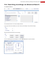
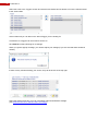
13.2 Searching recordings via Advanced Search .................................................................................... 79
5
6
FastTrace 2
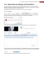
13.3 Searching recordings via Postmotion .............................................................................................. 81
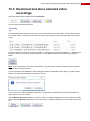
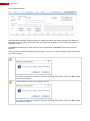
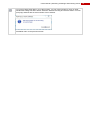
13.4 Download and store selected video recordings ............................................................................... 83
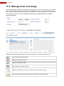
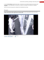
13.5 Manage local recordings .................................................................................................................. 86
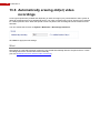
13.6 Automatically erasing old(er) video recordings................................................................................ 88
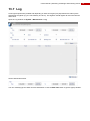
13.7 Log ................................................................................................................................................... 89
13.7.1
Example of a Log record .......................................................................................................... 91
13.7.2
Example of an Event record .................................................................................................... 91
13.7.3
Example of a Command record ............................................................................................... 91
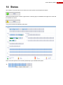
14
Status ................................................................................................................................................... 93
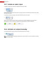
14.1 Isolate an alarm input ...................................................................................................................... 94
14.2 Activate an output manually............................................................................................................. 94
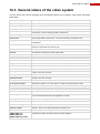
14.3 General status of the video system ................................................................................................. 95
15
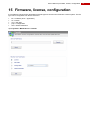
Firmware, license, configuration .......................................................................................................... 97
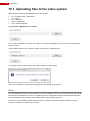
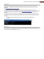
15.1 Uploading files to the video system ................................................................................................. 98
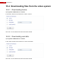
15.2 Downloading files from the video system ...................................................................................... 100
15.2.1
Downloading license .............................................................................................................. 100
15.2.2
Downloading user data .......................................................................................................... 100
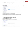
15.2.3
Downloading a configuration ................................................................................................. 101
15.2.4
Downloading camera definitions ............................................................................................ 101
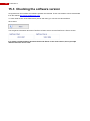
15.3 Checking the software version....................................................................................................... 102
16
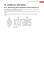
Additional information ........................................................................................................................ 103
16.1 Retrieving the IP address of the FastTrace 2 ................................................................................ 103
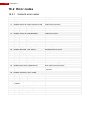
16.2 Error codes .................................................................................................................................... 104
16.2.1
General error codes ............................................................................................................... 104
16.2.2
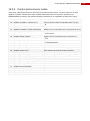
Control protocol error codes .................................................................................................. 105
16.2.3
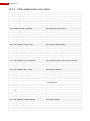
Filter graph/codec error codes ............................................................................................... 106
User‟s Manual | Safety instructions
1
Safety instructions
CAUTION
RISK OF ELECTRIC
SHOCK, DO NOT OPEN!
CAUTION: TO REDUCE THE RISK OF ELECTRICAL SHOCK, DO NOT REMOVE COVERS. NO USER SERVICEABLE
PARTS INSIDE. REFER SERVICING TO QUALIFIED SERVICE PERSONNEL.
WARNING: TO REDUCE THE RISK OF FIRE OR ELECTRIC SHOCK, DO NOT EXPOSE THIS
APPLIANCE TO RAIN OR MOISTURE.
The lightning flash with an arrowhead symbol within an equilateral triangle is intended to
alert the user to the presence of uninsulated “dangerous voltage” within the product‟s
enclosure that may be of sufficient magnitude to constitute a risk of electric shock to
persons.
The exclamation mark within an equilateral triangle is intended to alert the user to
presence of important operating and maintenance (servicing) instructions in the literature
accompanying this appliance.
Environmental information
The crossed-out container indicates the fact that within the European Union this
product has to be offered for separate waste collection at the end of the product‟s
lifespan. This goes for the product, but also for all accessories that are included and
bear the same label. Do not put these products with domestic garbage.
For more information about the ways to collect, reuse en recycle, please contact your
local Waste Service. You can also contact Xtralis for more information about the
environmental aspects of our products.
Clarification
Adpro‟s FastTrace 2 is the newest ADPRO product concerning video recording. Hence, FastTrace 2 is also
compatible with:
FastTrace
V3100
V3100 FT
V3100 HYBRID
You can upgrade firmware and software of the products mentioned above to the newest FastTrace 2
firmware and software. Please do take into consideration that the FastTrace 2 videosystem could have other
system requirements than any other previous ADPRO products!
7
8
FastTrace 2
User‟s Manual | Hardware
2
2.1
Hardware
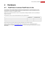
FastTrace 2 versus FastTrace 2 Lite
The FastTrace 2 Lite has been designed, developed and manufactured as a complete FastTrace 2 video
security system, but the ENTRY system license that is included, limits the number of cameras that can be
supported to a maximum of 4 analogue cameras.
Please also note that the FastTrace 2 Lite can only operate on analogue cameras, there is no possibility to
support IP cameras.
The FastTrace 2 Lite can only be purchased with an entry system license:
Full system license
TX (transmission) only license
Entry level license
FastTrace 2
FastTrace 2 Lite
See the FastTrace 2 technical manual for further information on the system licenses.
Please consult the ADPRO commercial data sheet on the FastTrace 2 Lite. This data sheet can be
downloaded from our website www.xtralissecurity.com. You don‟t need to login to download the commercial
data sheets!
9
10
FastTrace 2
2.2
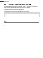
FastTrace 2 versus FastTrace 2
®
TM
The FastTrace 2 is the newest hardware in the ADPRO FastTrace series. It has been developed as a
more powerful video system with higher performance and more efficient operation.
The most important difference is the possibility to have 16 analytic channels with the FastTrace 2, while
the FastTrace 2 is limited to a maximum of 4 analytic streams.
The FastTrace 2 can also be purchased with a full or tx only system license:
Full system license
TX (transmission) only license
Entry level license
FastTrace 2
FastTrace 2
See the FastTrace 2 technical manual for further information on the system licenses.
Mind:
The FastTrace 2X requires the minimal software version 2.6!
Please note:
Wherever in this document the term FastTrace 2 is used, you can assume that the term refers to both the
FastTrace 2 and the FastTrace 2X, unless specifically mentioned otherwise!
User‟s Manual | Hardware
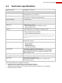
2.3
Technical specifications
Operating system
PC platform – Linux OS
Network protocols
TCP, UDP, FTP, TELNET, HTTP, SMTP, RTSP, RTP
Bandwidth
Remotely adjustable: compression, ips and quality.
A bandwidth limit can be specified.
Bandwidth consumption
6 ips CIF/SIF: 70 kb/sec
12 ips 4CIF/SIF: 400 kb/sec in optimal quality
Software updates
Local and remote
Maximum number of cameras
16 (total of analogue and IP cameras)
Web server
Integrated
COM ports
4 USB interfaces used for:
- PTZ control (requires USB RS485 convertor)
- PSTN or ISDN modem
Ethernet
10/100/1000 Base-T, auto detection, full duplex, RJ45
Storage
up to 4 devices (connected through SATA interfaces);
following arrangements are possible:
- 1 to 4 hard disks (500 GB to 2 TB)
Remark: There are USB connectors accessible on the back of the
FastTrace 2 video system; and also 1 USB connector is on the front
to which a portable DVD writer can be connected to export video
sequences.
Remote visualisation
Internet Explorer; Windows XP, Windows Vista, Windows 7,
Windows Server 2003
Management
-
Power supply
100~240 VAC, 50/60 Hz (+80% efficiency)
! The video system has to be connected to a 230 VAC/16A
mains outlet with proper earth, applying a separate locally
approved power cord.
Operating temperature
5 – 40°C (see also 1.3 Fan speed selection)
Humidity
20 – 93% (non-condensing)
Dimensions
445x132,50x300 (WxHxD in mm)
Rubber feet can be fixed on the bottom. The height is then
increased with 2.5 mm.
Internet Explorer (installs Client software)
VSKwin software
M3000 software
VideoCentral Platinum
3rd party CMS software
Multi-site FASTTRACE 2 configuration is possible:
Integration of up to 10,000 FastTrace 2 video security systems.
Remote video and audio, live video and consultation of recordings.
Compatible with FOXnet®Plus, FALCONnet, S3100, Presidium, VSKwin®, VCP and M3000.
SDK for third party integration.
11
12
FastTrace 2
2.4
Front LED indicators
On the front of the FastTrace 2 video system are 3 LEDs:
Green LED
Power is on
Yellow LED (*)
Fault
Blue LED
Storage media activity
Only the green and blue LED could be lit all the time. If you see the yellow LED lit, you should check the
status of your FastTrace 2 video system.
(*) The yellow LED can only be lit when a Main I/O card has been installed.
Remark:
When the 3 LEDs are flashing simultaneously, the system is busy updating the recordings discs. Do not turn
off power in that case!
User‟s Manual | Client Setup and Configuration
3
3.1
Client Setup and Configuration
Initial configuration
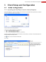
3.1.1 Launching the FastTrace 2 client in Internet Explorer
Open Internet Explorer. Type the IP address of the FastTrace 2 in the address bar (by default the IP address
is 10.0.0.10 with subnet mask 255.255.255.0).
Provide a valid username and password.
3 users are by default validated in the FastTrace 2:
User “0” with default password “666777”
User “1” with default password “666777”
User “15” with default password “666777” (= technician)
If required, change the language and check whether your work folder (= the folder in which downloaded and
local recordings are stored) is correct.
Click
when you can’t see the work folder path!
Click „Login‟.
Mind:
It might occur that the internet
browser is opened instead of the
login screen. If this is the case,
just click “Retry”.
13
14
FastTrace 2
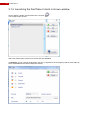
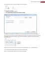
3.1.2 Launching the FastTrace 2 client in its own window
On the desktop, double click the FastTrace 2 shortcut:
You will get a login window:
.
Select the desired video system from the list and click Connect.
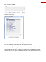
Via Settings you can change the language, the skin (= appearance of the program) and the work folder (in
which downloaded and local recordings are stored):
User‟s Manual | Client Setup and Configuration
Via Edit you can modify necessary ports or change user (with valid password). It is also recommended to
provide a useful and meaningful name for your video system.
Mind:
The client software by design requires a minimum screen size of 1024x768. All screens have been designed
in that resolution. If your screen is not 1024x768, you should open the client in Internet Explorer (or any other
internet browser).
15
16
FastTrace 2
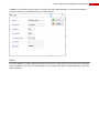
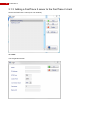
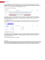
3.1.3 Adding a FastTrace 2 server to the FastTrace 2 client
Launch the FastTrace 2 client (in its own window).
Click Add.
You will get this window:
User‟s Manual | Client Setup and Configuration
Please fill in all necessary information.
Enter a description as “Name”. It is recommended to provide a meaningful description to your FastTrace
2 video system!
Enter the IP address of the FastTrace 2 (by default 10.0.0.10).
Set RTSP port and Control port. Use the same ports as specified under System > Ethernet/PPP (see).
Select the TCP or UDP protocol. UDP is recommended, but TCP may be required if the connection goes
through a router that blocks the UDP packets.
Enter the username and password of an existing user. By default you can log on with user “0” and
password “666777”.
Click OK to save the added device.
At this time you can select the newly added video system from the list and connect to it.
17
18
FastTrace 2
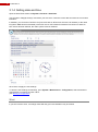
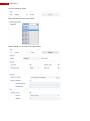
3.1.4 Setting date and time
Open the Date/Time window via System > General > Date/Time.
Tick the option “Daylight savings” and select your time zone. Click the correct date and enter the correct time
indication.
If available, you can let the FastTrace 2 synchronise with an NTP server. Enter the IP address (or the name
if Dynamic DNS has been activated) of the NTP server. NTP stands for Network Time Protocol. When an
NTP server has been defined, the video system must be restarted.
Click „Save‟ to apply the new settings.
To store the new settings permanently, open System > Maintenance > Configuration, select the desired
configuration to overwrite and click „Save‟.
(see Storing a configuration)
Mind:
If you turn back the clock, recordings made after the given time indication may be erased.
User‟s Manual | Users
4
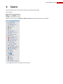
Users
Launch the FastTrace 2 Client and connect to the desired video system.
Click „System‟.
Open the „Users‟ menu via System > General > Users (by clicking in the menu on the left):
You will get this section on the right of your window:
19
20
FastTrace 2
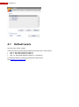
4.1
Default users
Up to 32 users can be created.
Three users are by default already defined in the FastTrace 2 video system:
User “0” with default password “666777”
User “1” with default password “666777”
User “15” with default password “666777” (= technician)
It is always possible to change the passwords of these users.
(see Modifying an existing user).
User‟s Manual | Users
4.2
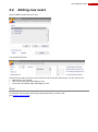
Adding new users
Open the Users window and click „Add‟.
You will get this window:
Choose a free number. Enter the name of the user and choose the desired type. You can choose from:
Administrator: has all rights.
User: has specific rights, adjustable per user.
Technician: has specific rights, adjustable per user.
Mind:
! A technician can only log in after being granted permission by another user.
(see Granting the technician)
21
22
FastTrace 2
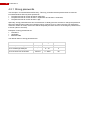
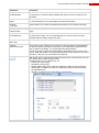
4.2.1 Strong passwords
Tick the option “Increased Password Security”. This way you define that the password has to meet the
increased Windows Security about passwords:
The password has to contain at least 8 characters;
The password has to contain at least 1 capital letter and at least 1 small letter;
The password has to contain at least 1 digit.
Optionally, strong passwords also have a limited time of validity (the user will have to change the password
before the defined period ends) and a limited number of retries to log on. When the user has reached the
maximum number of retries, the account will be temporarily blocked. The time of blocking the password has
to be set (value in seconds).
Examples of strong passwords are:
Tmus001cl
12rtSV5km
aiGP5rsLZa89
The default values of strong passwords are:
Parameter
Unit
Range
Default value
Maximum password age
Day
0 – 120
0
-
0 – 10
3
Second
0 – 3600
60
Nr of invalid login attempts
Nr of seconds user is blocked
User‟s Manual | Users
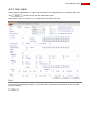
4.2.2 User rights
When adding an Administrator, no rights need to be defined. An Administrator has by default all rights. Just
click
to create the new user with administrator rights.
When adding a User or Technician, you need to specify the rights of this user:
Hint:
If you want to untick all options (rights), you can click „Clear‟. All options will be unticked, yet the user itself
will not be deleted!
23
24
FastTrace 2
4.2.2.1
Live video
You can define on what cameras a user may watch live images and whether the user can control PTZ and
define presets for PTZ cameras.
You can define whether the user can use these functions within the Live Video window:
Right click menu: the user can change the image quality.
Snapshot: the user can take a snapshot of the image of the selected camera or all cameras.
Local recording: the user can record images from a selected camera and store these recordings locally.
Note: All other functions in the Live video window are by default accessible to every user!
4.2.2.2
Recordings
You can define whether a user can watch recordings (either on Timeline/Postmotion or Backup or both) and
on what cameras these recordings may be watched.
Note: when the user cannot watch Backup recordings, the user also cannot backup any recordings!
4.2.2.3
System settings
You can define whether the user has access to the system settings (= menu „System‟). If you grant the user
access to the system settings, you can specify the rights by ticking the options which the user can access.
4.2.2.4
Status
You can define whether the user has access to the status menu and when access has been granted,
whether the user can isolate alarm inputs and/or activate outputs.
User‟s Manual | Users
4.2.2.5
Granting tech rights
When you tick the option “Set tech rights”, you allow this user to grant access for the technician users.
(see Granting the technician)
You can also define whether or not the user can arm the video system (change the operational modus).
(see Operational mode)
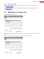
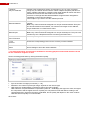
4.3
Modifying an existing user
Open the Users window and click „Edit‟.
Change whatever settings you desire and click „Apply‟ to save the changes. Don‟t forget to „Save‟ the new
settings.
When you want to delete a user, select the user you want to delete and click „Remove‟.
25
26
FastTrace 2
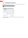
4.4
Granting the technician
Open the Users window and click „Enable‟. Mind: you can only enable the technician grant if you have the
right to do this.
To disable the technician grant, follow the same procedure. The technician grant is also disabled when
rebooting the video system.
User‟s Manual | Using IP cameras
5
5.1
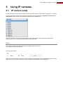
Using IP cameras
IP camera setup
IP cameras can be connected to the HIPI card or to the main network. 1 HIPI card is required per 8 cameras.
To add an IP camera, you need to connect the camera to the network and open System > Connections >
Video inputs. Then choose a free camera number from the dropdown list:
Up to 16 cameras can be connected to the FastTrace 2 video system. Up to 8 cameras 1 HIPI card is
sufficient, from up to 9 cameras you will need a second HIPI card.
Mind:
You need to configure the HIPI card(s) before configuring the IP cameras.
(see FastTrace 2 technical manual)
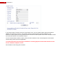
Tick the IP cam option:
Select the camera brand and enter the correct IP address, the username and corresponding password of the
camera (e.g. “root” for Axis cameras). Check the camera documentation for this password!
27
28
FastTrace 2
If you tick the option Treat this cam as a single stream cam, only one stream will be used for all features
related to the FastTrace 2 server. This means, however, that there will be specific limitations in the
FastTrace 2 video system: the only stream that the FastTrace 2 video system will use is the analytics stream.
As a result this will be a CIF resolution at 5 fps.
You can set the stream number as well, yet this must be checked on site, as this depends on the stream
number being used by the other application.
This advanced setting should only be modified for installing purposes and should therefore be left
for the installation engineer to edit!
Click „Enable‟ to start using the IP camera.
User‟s Manual | Using IP cameras
Then complete these parameters:
5.1.1 General parameters
Name
Enter a description for the camera (max 20 characters).
It is recommended to use a meaningful and relevant description.
PIR integrated on
camera
Check this option when a PIR has been integrated on this camera.
5.1.2 Overlay
Local time
Tick this option if you want to visualize the local time on the camera live image.
Camera name
Tick this option if you want to visualize the camera name on the camera live
image.
Text brightness
This option is not available for IP cameras. The parameter can be added to the
IP camera settings via the web browser.
Site name
Tick this option if you want to visualize the site name on the camera live image.
29
30
FastTrace 2
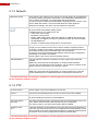
5.1.3 Network
Default live preset
When watching live images from a camera, the image quality can be adjusted at
any time by clicking your right mouse button. The initial quality, applied the first
time you select the camera, can be specified with this parameter.
You can choose from different preset qualities, depending on the camera. If you
choose “Hard disk stream”, live pictures will follow the same quality as
continuous recordings. This way, only two streams are required.
With certain types of IP cameras this button becomes active. Via this button you
can open the list with possible quality presets.
The parameters you can modify here, are:
- Frames per second (fps)
- Resolution of the picture
- Quality: VBR quality (Qlow, Qnormal of Qhigh) or CBR bit rate (20 through
2048 kbps). The higher the value, the better the quality, but also the higher
the bandwidth use!
Remark: for stable image quality VBR is recommended.
Only live multicast *
Multicast is the simultaneous supply of information to one or more computers
through only one stream from the source. When multiple computers poll this
one stream, multiple copies will be created, but the initial upload will remain the
same. Multicast thus ensures less data traffic over the network.
The 224.0.0.0 through 239.255.255.255 address range has been assigned for
multicasting on the local LAN network.
Tick this option if you want to use the multicast protocol.
Multicast address *
Enter the address to which the FastTrace 2 video system has to send the
multicast.
Mind: every camera should be assigned to a unique multicast address.
Everyone who has subscribed to the multicast, can view the live images on this
address, using a web browser or a FastTrace 2 Client.
Multicast port *
Enter the multicast port through which the FastTrace 2 has to send the stream.
Mind: every camera should be assigned to a unique multicast port. This port
must be defined by the IT Department before connecting the FastTrace 2.
* This advanced setting should only be modified for installing purposes and should therefore be left
for the installation engineer to edit!
5.1.4 PTZ
Use PTZ Control *
Tick this option if you have installed a PTZ camera.
Protocol *
Choose the corresponding protocol for the IP camera you have installed.
Address *
Enter the correct camera address for the IP camera you have installed. Check
the camera settings to know the camera address.
Auto-Home Expire
Time (sec) *
This value indicates the time in seconds that has to be expired after every PTZ
action, before the PTZ camera will move back to its home position.
If the value is left to 0, the Auto-Home feature will be disabled.
Positioning Time
(sec.) *
PTZ preset positions can be selected via an input. When that input triggers the
PTZ action, the camera will move to the configured PTZ preset position, but the
alarm message of the input will be delayed until the PTZ preset positioning time
has expired. Thus no blurry images are recorded for quad images.
* This advanced setting should only be modified for installing purposes and should therefore be left
for the installation engineer to edit!
User‟s Manual | Using IP cameras
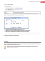
5.1.5 Recording
Continuous/Pre/Post
quality
This shows the quality that has been configured for continuous recordings and
for pre and post event recording.
Event quality
This shows the quality that has been configured for the event recording.
Set the recording parameters by clicking the desired quality.
Fps: the number of images (frames) per second (1 – 25);
Resolution: the number of pixels per image; depends on the camera type;
VBR: selects a variable bitrate compression (Qlow, Qnormal or Qhigh);
CBR: selects a compressed bitrate compression (value 20 – 2048 kbps); the higher the value, the higher
the compression and the higher the loss of quality; the compression levels will differ according to the
constant data flux in which the file size is predictable, but the quality will depend on the video contents.
VBR with Qnormal quality is recommended!
Click „Save‟.
Remark:
Before using the IP camera, you need to set up a static IP address in the camera, create a password for the
user “root” and set the date and time. You can adjust the time and date manually or you can synchronize the
camera in the FastTrace 2 to an NTP protocol.
Check the manual provided with the camera for more information on setting up the IP
address, password and clock.
31
32
FastTrace 2
User‟s Manual | Using analogue cameras
6
6.1
Using analogue cameras
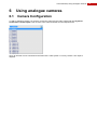
Camera Configuration
To add an analogue camera, you need to connect the camera to the video system and open System >
Connections > Video inputs. Then choose a free camera number from the dropdown list:
Up to 16 cameras can be connected to the FastTrace 2 video system. For every camera 1 A/V input is
required.
33
34
FastTrace 2
Tick the “analogue” option:
Select the BNC input and click „Enable‟.
When enabled you can adjust some parameters:
User‟s Manual | Using analogue cameras
Parameter
Description
* Type:
Enable/Disable
Choose whether you want to enable or disable this video input. When no camera
is connected, it is recommended to disable the input to ensure no faults can be
generated.
General:
Name
Enter a description for the camera (max 20 characters).
It is recommended to use a meaningful and relevant description.
Overlay:
Local time
Tick this option if you want to visualize the local time on the camera live image.
Overlay:
Camera name
Tick this option if you want to visualize the camera name on the camera live
image.
Overlay:
Text brightness
Tick this option if you want to choose the text colour of the overlay information on
the camera live image. It is recommended that you choose a text colour that
contrasts with the image background colour.
Overlay:
Site name
Tick this option if you want to visualize the site name on the camera live image.
Network:
Default live preset
When watching live images from a camera, the image quality can be adjusted at
any time by clicking your right mouse button. The initial quality, applied the first
time you select the camera, can be specified with this parameter.
You can choose from different preset qualities, depending on the camera. If you
choose “Hard disk stream”, live pictures will follow the same quality as continuous
recordings. This way, only two streams are required.
With certain types of cameras this button becomes active. Via this button you can
open the list with possible quality presets.
The parameters you can modify here, are:
- Frames per second (fps)
- Resolution of the picture
- Quality: VBR quality (Qlow, Qnormal of Qhigh) or CBR bit rate (20 through
2048 kbps). The higher the value, the better the quality, but also the higher
the bandwidth use!
Remark: for stable image quality VBR is recommended.
35
36
FastTrace 2
* Network:
Only live multicast
Multicast is the simultaneous supply of information to one or more computers
through only one stream from the source. When multiple computers poll this one
stream, multiple copies will be created, but the initial upload will remain the same.
Multicast thus ensures less data traffic over the network.
The 224.0.0.0 through 239.255.255.255 address range has been assigned for
multicasting on the local LAN network.
Tick this option if you want to use the multicast protocol.
* Network:
Multicast address
Enter the address to which the FastTrace 2 video system has to send the
multicast.
Mind: every camera should be assigned to a unique multicast address. Everyone
who has subscribed to the multicast, can view the live images on this address,
using a webbrowser or a FastTrace 2 Client.
* Network:
Multicast port
Enter the multicast port through which the FastTrace 2 has to send the stream.
Mind: every camera should be assigned to a unique multicast port. This port must
be defined by the IT Department before connecting the FastTrace 2.
* PTZ:
Use PTZ Control
Tick this option if you have installed a PTZ camera.
* PTZ:
Protocol
Choose the corresponding protocol for the camera you have installed.
* PTZ:
Adres
Enter the correct camera address for the camera you have installed. Check the
camera settings to know the camera address.
* This advanced setting should only be modified for installing purposes and should therefore be left
for the installation engineer to edit!
Set the recording parameters by clicking the desired quality.
Fps: the number of images per second (1 – 25);
Resolution: the number of pixels per image; depends on the camera type;
VBR: selects a variable bitrate compression (Qlow, Qnormal or Qhigh);
CBR: selects a compressed bitrate compression (value 20 – 2048 kbps); the higher the value, the higher
the compression and the higher the loss of quality; the compression levels will differ according to the
constant data flux in which the file size is predictable, but the quality will depend on the video contents.
VBR with Qnormal quality is recommended!
Click „Save‟.
User‟s Manual | Using analogue cameras
6.2
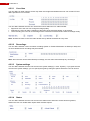
Camera URLs
You can always open a Client version for a specific camera via a web browser (e.g. Internet Explorer) if you
do not have the client software on your PC. You will need to install the ActiveX on your PC in order to be
allowed access.
To open a specific window of the client, provide the IP address of the FastTrace 2 in the address bar,
followed by /index.php? and – if required – also one of these parameters:
Parameter
Description
Possible values
page=
Open a certain menu in the client.
live
timeline
postmotion
status
settings
system
about
file
subpage=
Open a certain submenu in the client (can
only be used for the menus settings and
system).
motion
recording
addressbook
matrix
ethernet
video
audio
alarms
io
serial
videoic
alarmtx
email
clock
config
autostartmask=
This value sets the cameras you want to
see. The value should be a decimal
number corresponding to a binary code.
1 (binary 000I) = camera 1
3 (binary 00II) = camera‟s 1 en 2
8 (binary I000) = camera 4
username=
Enter the desired user.
0 (= administrator)
15 (= technician)
password=
Enter the correct password for the user.
666777
uid=
Download the selected recording.
0a0000f7a45a6500
uid_save_filename
=
Donwload the selected recording and store
it with the provided file name (= optionally).
notcp
By default TCP is used. If you want to use
UDP instead, you need to add this
parameter.
nogui
Use the simplified view (without menu).
To add multiple parameters in the address bar, type “&” between the parameters. Mind: no intervals are
allowed in the address bar!
An example: open camera 1 with UDP in simplified view
http://10.0.2.41/index.php?autostartmask=1&username=0&password=666777¬cp&nogui
37
38
FastTrace 2
User‟s Manual | Video monitor
7
7.1
Video monitor
Connection
A monitor can be connected to the SVGA or digital interface of the FastTrace 2 server. For a video monitor,
an external VGA to PAL converter can be used.
7.2
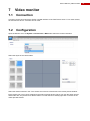
Configuration
Open the Monitor menu via System > Connections > Matrix and select the monitor resolution.
Select the layout of the virtual matrix.
Select the desired camera in the Tools section and click one of the boxes in the matrix preview window.
Each camera can only be once assigned to the matrix preview window. When you click the same camera
and another box, the previous box will be cleared. To clear the box manually right click on the box in the
matrix preview window.
39
40
FastTrace 2
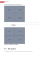
You can choose whatever order of cameras you like.
Click „OSD‟ if you want the camera name to be shown in the matrix. OSD stands for “On Screen Display”.
You need to click the
button to activate it. Then click all boxes you want OSD to be active in. The
indication OSD appears in the upper left corner of the box.
Click „Save‟ to safeguard the new settings.
7.3
Resolution
The image resolution for the monitor display is always CIF / SIF with Qnormal quality.
User‟s Manual | Alarms
8
8.1
Alarms
Arming/Disarming the video system
Events on the FastTrace 2 can be classified in the following groups:
system messages: these are internal events (e.g. hard disk error, power supply fault, communication
error, …);
camera messages (e.g. video signal missing, contrast level too low, motion detected, …);
network inputs: alarm inputs connected to external Net IO modules
inputs: alarm inputs connected to the OTB IO card, accessible at the back of the video system;
virtual inputs: events detected on interconnected S3100 security panels.
Events have to be handled in a different way when the building is left unattended. Therefore, the building has
to be armed. Arming can be done in three ways:
1) automatically according to a schedule;
2) manually, by a user who has to activate a switch;
3) by the CMS, executing the DN command line in TELNET (hint: type HE for syntax help).
To define the behaviour of an alarm input during armed and disarmed state, modify the alarm profile that is
assigned to this input.
Remark:
It is possible for other software developers to use the SDK (software development kit) in order to arm/disarm
a building.
41
42
FastTrace 2
8.1.1 Arm/Disarm schedule
To insert a schedule to automatically arm/disarm a building, open Settings > Behaviour > Arm/Disarm
schedule.
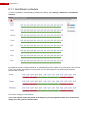
By default the system is always disarmed. To automatically arm the system for a given period, click „Armed‟
in the Tools section and drag the mouse pointer over the desired period. The selected period will be
indicated with a red bar.
Click „Save‟ to apply the new settings.
! The video system will be (dis)armed at the beginning of the programmed time zone. A switch can
always force the system to another state.
User‟s Manual | Alarms
Hint:
To zoom in on a part of the day, position the mouse pointer on the time scale, press the left mouse button
and drag the mouse to the right (drawing a blue line). Release the mouse button.
To zoom out, position the mouse pointer on the time scale and click the right mouse button.
8.1.2 Arm/Disarm Switch
To define an arm/disarm switch, check the FastTrace 2 technical manual.
43
44
FastTrace 2
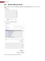
8.2
Email address book
Open the address book window via System > Behaviour > Email Addressbook. Click „Add‟ to add a new
contact.
A new section will appear to the right.
Enter the name and email address of the recipient.
User‟s Manual | Alarms
Select the different notifications that you want to send to this recipient. You can add selections by selecting a
trigger and clicking „Add‟.
You can also delete a trigger from the list. Select the desired trigger in the list and click „Delete‟. This will only
delete the trigger from the recipient‟s list of triggers, and not the trigger itself.
Click „OK‟ and „Save‟ to apply the new settings.
Remark:
If the event has a “silent alarm” profile, no mail will be sent to any of the recipients!
45
46
FastTrace 2
User‟s Manual | Operational mode
9
Operational mode
The video system can be switched to 4 different operational modes. Each mode can affect the behaviour of
the video recorders.
Mode selection can be done:
Automatically according to a time schedule;
Manually (by activating an input);
Via the CMS (= execution of a TELNET command). (For syntax help in TELNET, type HE)
It is also possible for third party software using the Adpro FastTrace 2 Software Development Kit (SDK) to
change the operational mode.
To create a video recording that behaves differently in function of the selected mode, read the chapter on
Recording.
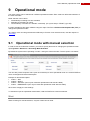
9.1
Operational mode with manual selection
In order to use the mode time schedule, you need to specify the times for changing the operational mode.
Open System > Behaviour > Recording Mode Schedule.
By default the system will be operating in mode 1 during the whole schedule. Tick the option “Use switch”.
You can also provide a specific name (max 20 characters) for each operational mode. It is recommended to
use a meaningful and relevant description.
Example of relevant description:
mode 1 = DAY
mode 2 = NIGHT
mode 3 = HOLIDAY (can only be used with operational mode with time table)
mode 4 = EMERGENCY (can only be used with operational mode with time table)
Click „Save‟ to apply the new settings.
To activate an input as operational mode switch, read the FastTrace 2 technical manual.
Mind:
When choosing for manual selection, only two modes can be used!
47
48
FastTrace 2
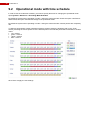
9.2
Operational mode with time schedule
In order to use the mode time schedule, you need to specify the times for changing the operational mode.
Open System > Behaviour > Recording Mode Schedule.
By default the system will be operating in mode 1 during the whole schedule. Untick the option “Use Switch”.
When ticked, this option sets manual change of the operational mode.
By default the system will be operating in mode 1 during the whole schedule. All time periods are completely
red.
To define a period where another operational mode is required, select the desired mode (in the “Tools”
section) and drag the mouse pointer over the desired period. The selected period will be indicated in another
colour:
red = mode 1
green = mode 2
yellow = mode 3
blue = mode 4
Click „Save‟ to apply the new settings.
User‟s Manual | Configuration
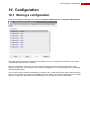
10 Configuration
10.1 Storing a configuration
Open the “Configuration Management” window via System > Maintenance > Configuration Management.
The video system can store up to 8 different configurations. Only 1 configuration can be active. The active
configuration is marked with an asterisk.
Select a configuration. Click „Save‟ to store the current settings under the selected configuration. Click
„Rename‟ to provide a new description to the selected configuration. It is recommended to use a meaningful
and relevant description.
You can also copy the selected configuration by clicking „Copy‟. At that moment the „Paste‟ button becomes
active. You can now choose another configuration and click „Paste‟ to provide the same settings to the newly
selected configuration. Afterwards (small) modifications can be made to the new configuration.
49
50
FastTrace 2
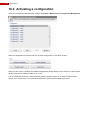
10.2 Activating a configuration
Open the “Configuration Management” window via System > Maintenance > Configuration Management.
Select a configuration from the list and click „Activate configuration‟ in the “Boot” section.
When you click „Factory defaults‟ all modified configurations will be deleted. Your FastTrace 2 video system
will also be given the default IP address 10.0.0.10!
You can restart the FastTrace 2 video system by clicking „System restart‟. If you want to stop the video
system, click „System halt‟. It is recommended to halt the system before switching off power.
User‟s Manual | Watching live images
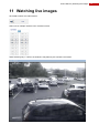
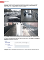
11 Watching live images
Click Live to watch live video streams.
Select one or multiple cameras in the Cameras section.
When selecting only 1 camera, the window is fully taken by this camera‟s live stream.
51
52
FastTrace 2
When selecting multiple cameras, several camera streams will be visualized. The layout is rearranged
automatically, to make sure all images are equally large. If you select 2 to 4 cameras, the display will
automatically adjust to “quad” (= 4 images). With 5 to 9 cameras selected, you will automatically get 9
images and with 10 to 16 selected cameras, you will see 16 images.
You can double click (with the left mouse button) one of the images to get a full screen view of the specific
image. Double click it again to see all the images.
The quality of the image (resolution) has been defined in the video settings. Open System > Connections >
Video inputs and select the desired video.
To adjust the quality of the image temporarily in the Live mode, click the right mouse button and select one
of the options.
User‟s Manual | Watching live images
The options that are given depend on the type of camera you are using.
Limitations on live video streaming
For DS40xx A/V cards there is one separate video processor for each group of 4 analogue cameras (video
in 1-4, 5-8, 9-12 and 13-16). If 4CIF resolution is applied to at least one camera within the same group,
following limitations will apply to live streaming within this group of cameras (due to processor limits):
Number of enabled cameras
within the same group
Live video resolution
1–2
no limits
3
only QCIF or CIF (25 ips);
or the same quality as recording (hard disk stream)
4
only QCIF (25 ips);
or the same quality as recording (hard disk stream)
For DS42xx A/V cards the limitations are set per camera (and no longer per camera group). If recording
quality is set to 4CIF/4SIF the maximum quality for Live viewing is CIF/SIF or QCIF/QSIF or the same quality
as recording (hard disk stream). When 2CIF/2SIF is applied for recording, only CIF/SIF, QCIF/QSIF and
2CIF/2SIF are possible with live viewing. Each time the maximum fps (images per second) equals 25. All
other combinations are of course possible.
Live streaming quality is defined under System > Connections > Video inputs > Network: Default live
preset.
53
54
FastTrace 2
To set 4CIF/4SIF as default live preset, you need to define the recording quality to 4CIF/4SIF first, and select
hard disk stream as default live preset.
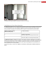
11.1 Enable/disable analytic bounding box
rendering
The bounding boxes of the analytics can be displayed in the live and recorded view. This feature can be
enabled/disabled in the Cameras section by clicking the eye button.
The analytic bounding box rendering is enabled. This is also the default setting.
The analytic bounding box rendering is disabled.
User‟s Manual | Watching live images
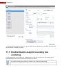
11.2 Tools
To the right you can find the section “Tools”. Here you can start/stop a manual recording and/or take a
snapshot image of a specified live stream view.
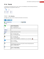
11.2.1 Info display
Click Info in the section Tools to visualise the information of the camera:
Legend:
Video streaming status:
- green = connection OK
- red = connection error
- grey = camera not connected
Camera name
Resolution
Number of frames per second
Local video recording (on hard disk of your PC):
- red = recording locally
- grey = not recording locally
Audio recording:
- red = recording audio
- grey = not recording audio
When no audio is available the loudspeaker icon is crossed out:
Video recording (on the hard disk of the video system):
- blue = recording
- grey = no recording
Tamper alarm!
The camera lens is covered or the system has been damaged/opened.
- green = tamper alarm active
- grey = no tamper alarm
Motion detection
- green = motion detected
- grey = no motion detected
55
56
FastTrace 2
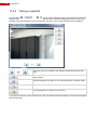
11.2.2 Taking a snapshot
Via the button
you can take a snapshot image of the video streams that are
being shown at that specific moment. These snapshots can be stored as image (jpg format) on your local
hard disk (or a network folder you can access from your PC). You can also directly print the snapshots.
Use these arrows to navigate to the different snapshots that have been
taken.
Save the snapshot that is shown to a folder on your local hard disk or a
network folder.
Save all snapshots to a folder on your local hard disk or a network folder.
Print the snapshot that is shown to a printer of your choice.
Print all snapshots to a printer of your choice.
If you select an image (= click the image in the live view with the left mouse button), a red border will appear
around that image.
User‟s Manual | Watching live images
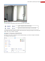
You notice that two extra buttons have become active in the “Tools” section:
Take a snapshot of the selected image.
Record the selected camera locally on your hard disk.
The snapshot file names contain the camera number and the time of taking the snapshot in the format year –
month – day – hour – minutes – seconds.
By default the work folder is selected to store the snapshot images. If you want to change the work folder,
click „Settings‟ at the login window:
57
58
FastTrace 2
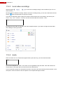
11.2.3 Local video recordings
With the buttons
network folder).
you can store recordings locally (on the hard disk of your PC or a
Click the button to start the recording. When a camera is recording locally, you can see a blue ball in the info
section:
. Click the same button to stop the recording.
The video recording file names contain the camera number and the time of recording in the format year –
month – day – hour – minutes – seconds. The files are stored with the extension “.hbox”.
By default the work folder is selected to store the snapshot images. If you want to change the work folder,
click „Settings‟ at the login window:
11.2.4 Audio
Select a camera. If it is a camera that supports audio (see Audio IN), you can activate the audio.
Click on the loudspeaker to listen. The volume can be regulated through the slider. Click and hold the left
mouse button on the slider and move the mouse to the desired level.
You can also talk to people if a microphone has been connected. Click and hold the left mouse button on the
microphone. Also the volume of the microphone can be adjusted through the slider.
User‟s Manual | Watching live images
11.3 PTZ control
In the section PTZ you can control the PTZ camera.
Use the arrows to move the camera to the left or right and up or down. Use
the “Home button” in the middle to move the camera to the selected preset
position (= start position).
When this button is lit (orange arrows), you can use digital zoom. Simply
select a camera and you will see that the mouse indicator changes. Click
the left mouse button and hold it to zoom in. To zoom out press the Shift
key and the left mouse button. When zoomed in, the text “Digital Zoom”
appears (in green letters) on the image.
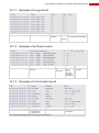
This slider adjusts the moving speed of the PTZ camera when using the
player‟s built-in controls.
With this function you can zoom in or zoom out on a selected image.
Click the middle button to manually adjust the focussing. Use the + and –
buttons to adjust.
Click to manually adjust the iris. Use the + and – buttons to adjust.
Click to wash and/or wipe the lens of the outdoor camera. The camera has
to have this feature of course.
Store the camera position.
Open the drop-down list to select one of the 4 possible camera preset
positions. Click the floppy disk button to store the actual camera position in
the selected preset number. Click the waistbin button to remove the preset
position from the list.
Enable or disable the selected auxiliary function on the camera. Auxiliary
camera functions vary depending on the camera model. Please read the
ADPRO Tech Tips for more information about auxiliary camera functions.
59
60
FastTrace 2
PTZ shortcut keys on the keyboard:
Arrow keys (up, down, left, right);
separate arrow keys on the keyboard or arrow keys on the numeric keyboard (with Num Lock OFF)
Home = Zoom in;
Page Up = Zoom out;
End = Focus near;
Page down = Focus far;
Shift = Shift key enabled (only applies to new PTZ control).
IMPORTANT:
Telemetry station manufacturers provide a variety of models and features. The FastTrace 2 provides PTZ
control ability for a number of popular models and where possible, supports the features provided by the
manufacturer. Due to the number of models available on the commercial market details of connection and
use for individual models have been provided in this manual. Xtralis does, however, have tech tips available
for these cameras on the website http://www.xtralissecurity.com.
User‟s Manual | Recording
12 Recording
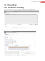
12.1 Continuous recording
Open the Recordings Behaviour window via System > Behaviour > Recordings Behaviour.
To add a new recording, enter a name (max 20 characters) and click Add.
61
62
FastTrace 2
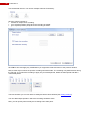
Tick the desired camera. You can tick multiple cameras if necessary.
Click the camera number to:
activate an output when recording;
go to a preset position (PTZ) when the recording is started;
go to a preset position (PTZ) when the recording is ended.
Click OK to save and apply any modifications you might have made and return to the previous window.
Next, tick the days on which the specific recording should be made. The recording is by default active during
the full year. If you want this recording to apply only for limited periods, delete the listed period and add a
customized period.
The last checkbox you can tick refers to holidays that have been defined (see Adding holidays).
You can add multiple periods in which the recording should be active.
Next, you can specify when exactly the recording has to take place.
User‟s Manual | Recording
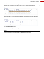
Select Time based to activate the recording in function of a time schedule. Click and hold the left mouse
button and drag the mouse over the Continuous time scale to mark the time zone during which the recording
should be active. To correct for errors, right click the time scale to clear the time zone and retry.
Up to 8 time zones can be defined!
Select Mode based to activate the recording in function of the operational mode of the video system. The
operational mode (1 to 4) is programmed automatically (with mode schedule) or manually (with switch).
See also Operational mode.
Tick Continuous for What to record.
Click OK and Save to apply the new settings.
Mind:
There is no continuous recording allowed with the TRANSMITTER license system!
63
64
FastTrace 2
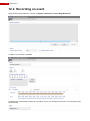
12.2 Recording on event
Open the Recordings Behaviour window via System > Behaviour > Recordings Behaviour.
To add a new recording, click Add.
A default name (“Recording condition #) is provided, but you can change this with your own description (max
20 characters).
User‟s Manual | Recording
Tick the desired camera. You can tick multiple cameras if necessary.
Click the camera number to:
activate an output when recording;
go to a preset position (PTZ) when the recording is started;
go to a preset position (PTZ) when the recording is ended.
Click OK to save and apply any modifications you might have made and return to the previous window.
Next, tick the days on which the specific recording should be made. The recording is by default active during
the full year. If you want this recording to apply only for limited periods, delete the listed period and add a
customized period.
The last checkbox you can tick refers to holidays that have been defined (see 14.3 Adding holidays).
You can add multiple periods in which the recording should be active.
Next, you can specify when exactly the recording has to take place.
65
66
FastTrace 2
Select Time based to activate the recording in function of a time schedule. Click and hold the left mouse
button and drag the mouse over the Event time scale to mark the time zone during which the recording
should be active. To correct for errors, right click the time scale to clear the time zone and retry. To avoid any
conflicts, it is recommended to clear the Continuous time scale.
Up to 8 time zones can be defined!
On recording on event it is also possible to “lock” the recording. This means that the recording cannot be
erased automatically. Do mind: locked recordings can cause the hard disk to fill up until it is completely full.
At this state, an alarm will be generated: “15 - HARD DISK FULL”. When the hard disk is full no new
recordings will be stored!
Select Mode based to activate the recording in function of the operational mode of the video system. The
operational mode (1 to 4) is programmed automatically (with mode schedule) or manually (with switch).
See also Operational mode.
Tick Event for What to record.
On recording on event it is also possible to “lock” the recording. This means that the recording cannot be
erased automatically. Do mind: locked recordings can cause the hard disk to fill up until it is completely full.
At this state, an alarm will be generated: “15 - HARD DISK FULL”. When the hard disk is full no new
recordings will be stored!
Click OK and Save to apply the new settings.
Remark:
You could also tick the Continuous mode for What to record to create a mixed recording. Such recording
will record continuously at the chosen quality and will switch to another quality on the selected event(s).
User‟s Manual | Recording
In the section Events click Add.
You will get a popup window:
Select the desired alarm trigger and click OK.
Several conditions can be added. For each condition you should define whether the condition should also be
fulfilled (AND) or whether this condition alone should trigger the alarm (OR).
If you invert the alarm, the recording will start when the end-of-alarm is received.
In the section Recording length you can define the duration of the recording. It is possible to set a time (value
in seconds) for recording before, during and after the event. For recording during the event you have the
choice between Event duration or a predefined period.
When the triggers follow each other so quickly that the recordings overlap, the multiple recordings will be
melted into 1 recording. When you tick the option Always start new recording these overlapping recordings
will not be melted into 1 recording. This is, however, not recommended practice.
67
68
FastTrace 2
Click OK and Save to apply the new settings.
Remarks:
If recordings with different quality settings overlap, the highest quality and image rate will be applied.
The video system is limited to 16000 events a day. If more events occur on the same day, the video system
will automatically switch to continuous recording for all cameras. This will be seen on the time scale as blue
bars. All these recordings will have CIF resolution, 25 ips and quality 75 (level of compression).
With the TRANSMITTER system license the recording on event is fixed to 5 seconds on prerecording, 10
seconds on event recording and no post recording.
12.2.1 Edit recordings
To edit your recordings, you can simply open the Recordings behaviour window via System > Behaviour >
Recordings behaviour. Select one of the recordings in the list and click Edit (or you can double click the
recording in the list).
Adjust the desired parameters and click OK and Save.
User‟s Manual | Recording
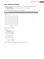
12.3 Adding holidays
The holiday calendar allows adjusting the behaviour of the video system during holidays. It affects:
your video recorders;
the operational mode of the video system (if managed by a mode schedule);
the arm/disarm schedule.
Open the Calendar window via System > General > Calendar.
Click Add to add new holidays.
Select the desired day and click OK. The selected day is shown in the list.
69
70
FastTrace 2
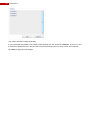
You need to add each holiday separately.
If you have mistakenly added a non-holiday, select the date from the list and click Remove. There is no need
to erase the holidays that are in the past, but it may be interesting to do so to keep a clear view of the list.
Click Save to apply the new settings.
User‟s Manual | Recording
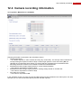
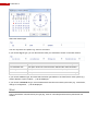
12.4 Camera recording information
Open System > Maintenance > Harddisks.
Following information is disclosed in the Information section:
Current write speed
The bitrate depends on video contents and may vary continuously. The average value is indicated in
red. By entering the required number of days in Show target speed to record and clicking Set you
calculate the corresponding write speed. The red line will then be displaced to the obtained result.
Recording behaviour will have to be modified to obtain the estimated bitrate.
Estimated hard disk storage capacity based on current measured bitrate
This value is expressed in number of days.
Estimated hard disk storage capacity based on existing footage stored on the hard disk
This value is expressed in number of days.
Free space for recording
This value is expressed in MB.
In the Harddisks section you get a list of all hard disks that have been installed in the video system. For each
hard disk you can see the free disk capacity and the total disk capacity.
71
72
FastTrace 2
User‟s Manual | Searching recordings and watching events
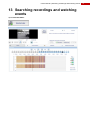
13 Searching recordings and watching
events
Open Recorded Video.
73
74
FastTrace 2
13.1 Searching recordings on the Timeline
Click Timeline.
13.1.1 Types of video recordings
Continuous recordings
Recordings on motion detection
Recordings on digital/virtual input
All other recordings
13.1.2 Searching on the timeline
Choose the desired period (month and year) by using the arrow buttons.
Select the desired day. Only days that light up in dark blue contain recordings. The darkest day is the
selected day.
By default the time indication is shown with a 30 minutes interval. You can, however, zoom in on the time by
dragging the mouse pointer (with the left mouse button pressed) on the time indication line. A blue marker
appears to indicate the selected time.
When you stop pressing the left mouse button, the system will zoom in on the desired period of time.
Select the timeline of the desired camera by clicking on that timeline with the left mouse button. A black
arrow appears.
User‟s Manual | Searching recordings and watching events
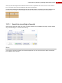
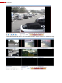
At the top left a still image of the selected camera is shown. Reposition the black arrow to choose another
time. The image at the top left is adapted to the new time indication.
You can also reposition the black delimiters on the selected timeline. In doing this you set the start and end
time of the video footage. It is the footage within this time frame that can be watched or downloaded.
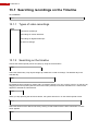
13.1.3 Searching recordings of events
At the top right select the option On event. You will be shown a list of available recordings. The list contains
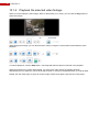
only event recordings, no continuous recordings.
Mind:
You only get to see the recordings of events that happened only 150 seconds before or after the selected
time indication on the timeline.
75
76
FastTrace 2
13.1.4 Playback the selected video footage
When you have selected a video image, either on the timeline or on event, you can click the Play button to
watch the footage.
While playing the footage, you can fast forward or rewind, using the control buttons underneath the video
playback.
To halt the playback, click the Stop button. The image will freeze at the time reached in the playback.
When the footage has not been downloaded, you cannot use audio. When the footage has been
downloaded you can adjust the volume level with the slider or click the loudspeaker button to mute all audio.
Double click the video player to get a full screen image. Double click again to quit the full screen player.
User‟s Manual | Searching recordings and watching events
13.1.5 Synchronized playback
To watch video footage of multiple cameras (with images of identical time settings), tick the camera timelines
you would like to include in the synchronised playback. Choose your time frame and click Play.
You will automatically get a full screen image with different camera footage.
When you double click one of the images, this image will be shown in full screen. Double click it again to
return to multiple playback.
77
78
FastTrace 2
You can also click the Info button to see the detailed information of each camera under the camera image.
User‟s Manual | Searching recordings and watching events
13.2 Searching recordings via Advanced Search
Click Advanced Search.
Tick the desired camera. You can tick multiple cameras.
In the Type section select whether you want to search all recordings or only locked recordings.
Select the desired time frame for the recordings.
You can manually type the time indication or use the Edit Time button to open this window:
79
80
FastTrace 2
Select the event in the Triggers section and click the blue double arrows button to move the selected event
to the second field.
At the bottom left you can filter on the kind of trigger you are looking for.
A maximum of 4 triggers can be moved to search on.
Click Search to start searching for recordings.
When you get this popup message, you need to adjust your settings (if you are sure that there should be
results).
If there are any results matching your search, they will be shown at the top right.
Select the desired recording. You can now watch and/or download this footage.
(see Download and store selected video recordings)
User‟s Manual | Searching recordings and watching events
13.3 Searching recordings via Postmotion
The video recorder does not only store the video footage on the hard disk, it also creates a metadata file
describing the contents of the footage. This information allows you to quickly find all sequences in which an
object was moving inside a specific area of the camera lens.
Select a desired camera image on the Timeline tab. (see Searching on the timeline)
Then click Postmotion.
Normally a still image is automatically available. If no still image has been defined on the timeline tab (e.g.
because you didn‟t leave the time to load the memory), you will get this error message:
If you did choose an image still (visible in the small screen at the top left), you will get this window:
In the still image at the top left a blue square appears. This blue square indicates your zone of interest. This
will be the zone that is being analysed. Adjust the size and position of the zone if desired and click Search.
When the search has been completed, you will get a time scale with the results.
81
82
FastTrace 2
Select the day of interest (only dates that light up dark blue contain recordings). Drag the mouse pointer on
the time indication line to zoom in on a specific period.
Click the right mouse button on the time indication line to zoom out to the original result display.
Click a specific recording and the Play button to watch that recording. Use the arrow buttons to go to the
previous or next recording.
Click Download if you want to store the footage in your work folder.
User‟s Manual | Searching recordings and watching events
13.4 Download and store selected video
recordings
Select the desired video footage and click Download.
You can see the downloading status:
The downloaded video footage are stored on your local hard disk in the work folder. The file name contains
the camera number, camera name and the time frame of the recording. The file is stored with the extension
“.hbox”.
For slow network connections it is recommended to – especially with synchronized playback – disable all live
streams in order to increase the download speed. You can disable all active live streams by clicking the
button.
Mind: when downloading a recording via Postmotion, only part of the recording will be stored: the selected
time plus about 10 extra seconds.
If you have already downloaded the video footage and click the „Download‟ button again, you will be asked
whether you want to download the recording once more:
You can also store video footage als image files on a USB drive of CD/DVD connected to the FastTrace 2
video system or to your local PC.
Use the Backup FastTrace 2 button to store the video on a USB or CD/DVD drive on the FastTrace 2 video
system. Use the Backup Local button to store the video on a USB or CD/DVD drive connected to your local
PC.
83
84
FastTrace 2
You will get this window:
Select the desired storage medium (CD/DVD or USB drive) and tick the desired cameras. Also define the
time frame of the recordings you want to store. If storing event recordings, you can select what events you
would like to store.
Click Start to start burning the video footage to the selected drive. Click Back to return to the previous
window.
When you have locked the recordings (see Recording on event), you need to manually unlock them so that
they can be deleted:
Click this button to unlock the selected recording.
You need to confirm that you want to unlock the recording. Click Yes to unlock, click No to return
to the previous window.
Click this button to unlock all recordings in the list.
You need to confirm that you want to unlock the recording. Click Yes to unlock, click No to return
to the previous window.
User‟s Manual | Searching recordings and watching events
If you have multiple hard disks in your video system, you can use this button to check on what
hard disk the footage has been stored. Select the desired recording and click this button. You will
get a popup window with the serial number of the hard disk.
Click OK to return to the previous window.
85
86
FastTrace 2
13.5 Manage local recordings
All downloaded video recordings are stored in the work folder of the FastTrace 2 Client on your local hard
disk (or network folder). Recordings are arranged in subfolders, providing a separate subfolder for each
video system. Video systems are recognized by their identifaction number (a value from 1 through 9999).
This identification number is defined via System > Behaviour > Alarm transmission > General >
FastTrace 2 Unit ID.
To watch locally stored video recordings, click Manage local recordings.
You will get this window:
Unfold the desired video system folder and select a recording. You now have several options:
Playback the selected recording.
Delete the selected recording.
Add the selected recording to the “burning” list. This is the list of files that you want to store
(burn) on CD, DVD or USB.
Delete the selected recording from the “burning” list. This is the list of files that you want to
store (burn) on CD, DVD or USB.
Select the desired drive on which you want to burn the video recordings.
Start burning the video recordings from the burning list to the selected drive.
User‟s Manual | Searching recordings and watching events
If you tick Include Player (at the bottom right), you will also burn all software required to watch the video
recordings, to the CD/DVD/USB. That way you can play the recordings on any Windows compatible
computer.
All drives used for burning video recordings are formatted before burning!
Remark:
If you want to play the video recording in full screen, double click the image (with the left mouse button).
Double click the full screen image to return to normal view.
87
88
FastTrace 2
13.6 Automatically erasing old(er) video
recordings
Local legal requirements (variable and depending on state and region) may necessitate the video system to
delete all recordings after some predefined period. The video recordings may only be stored on the hard disk
for a limited period of time. When that period of time has passed, the recordings should be erased from the
hard disk.
You can activate this function via System > Behaviour > Recordings behaviour.
Click Save to apply the new settings.
Mind:
Recordings on event that have been locked, are not erased automatically after the set period of time. These
recordings need to be unlocked and erased manually.
(see also Download and store selected video recordings)
User‟s Manual | Searching recordings and watching events
13.7 Log
Local legal requirements (variable and depending on state and region) may stipulate that a video system
should keep a logbook (e.g. the Law Sarkozy in France). This logbook should register all user interventions
and events.
Open the Log window via System > Maintenance > Log.
Set the desired time frame.
You can manually type the dates and time indications or click the Edit Time button to get this popup window:
89
90
FastTrace 2
Select the desired type.
You can only select one option: log, event or command.
If you choose log as type, you can also tick the views you would like to search in the Filter section.
Live video view
This option shows the users that have watched live video images.
Live multicast view
This option shows the users that have watched the multicast stream.
Still image view
This option shows the users that have taken snapshot pictures.
Recorded video view
This option shows the users that have downloaded video recordings.
If you choose event as type, all events that have been generated on the FastTrace 2 video system (e.g.
motion detection, inputs, outputs, …) will be displayed.
If you choose command as type, all commands that have been executed by the users (e.g. connections,
change of configuration, …) will be displayed.
Mind:
The log is limited to 100,000 events per type (log, event or command) and has a time period limit of 6
months.
User‟s Manual | Searching recordings and watching events
13.7.1 Example of a Log record
Time of intervention
Type of intervention
User of
intervention
Camera
of
interventi
on
Additional information
(e.g. moment of the still image)
13.7.2 Example of an Event record
Time of intervention
Identification of
intervention
Start or end
of
intervention
Type of
event:
- L=Live
- Q=Quad
- D=Duress
- S=Systeem
Additional
information
13.7.3 Example of a Command record
Time of intervention
Event identification. *
- C = client session
- T = telnet session
Executed command
Additional information
(e.g. IP adres)
* All commands within the same session will have the same ID.
91
92
FastTrace 2
User‟s Manual | Status
14 Status
Click „Status‟ to see the status of all cameras, the video system and all inputs and outputs.
Normally the Status button contains a green ball. If a warning sign is visualized there might be an issue with
the FastTrace 2 Server.
You get an overview with different status bars.
Place the mouse pointer on an indicator (status bar) to get a detailed description.
93
94
FastTrace 2
14.1 Isolate an alarm input
To isolate an alarm input, right click the desired input and click „Isolate‟.
Isolating an alarm input means that alarms are no longer received. The isolated input is marked with a brown
colour (see also legend).
To activate the isolated input again, right click the desired input and click „Isolate‟.
When an input is isolated, input I0511 will be activated. The message “GENERAL ISOLATION” will be
reminded each 24 hours. It will also be visualised in the Status button by a specific orange pin.
14.2 Activate an output manually
To manually activate an output, right click the desired output and click „Activate‟.
Mind: you cannot activate an output that is already active (= green colour). It is also not possible to manually
deactivate an active output.
User‟s Manual | Status
14.3 General status of the video system
You can receive one of these messages when checking the status of your cameras, video system and inputs
and outputs.
Cam x past analytics
Error during post motion analysis - contact your dealer.
Cam x sab analytics
Error in camera tampering analysis - contact your dealer.
Cam x recording
Camera images are currently being recorded to hard disk.
Cam x synch fault
No video signal on camera - check camera power supply or coax cable.
Cam x Contrast fault
Camera lens covered or lighting suddenly switched off.
Cam x Sabotage fault
Camera displaced or lens fault or zoom/focus settings changed.
Cam x event
User programmable camera event - has to be activated by a logical function.
Config uncommitted
Current configuration is not yet saved. Restarting the system may cause loss of latest
modifications.
Encoder card error
Video capturing card or HIPI card out of order. Could indicate a hardware fault. All
cameras on associated card will not work.
License error
Wrong license has been loaded or no license at all.
HD error
Hard disk fault. Requires hard disk replacement.
HD full
Hard disk full. Too many locked recordings are stored on hard disk.
HD corrupt
Indicates corrupt data - contact your dealer.
Db error
Indicates corrupt or unreadable data files - contact your dealer.
Entry error
Not disarmed in time on entry.
Exit error
Area not abandoned in time on exit (after arming the system).
Modem init failed
Modem not ready/not connected.
Primary line fault
Primary connection not ready.
Primary lifecheck
Life check sent over primary connection.
Backup line fault
Backup connection not ready.
Backup lifecheck
Life check sent over backup connection.
AL tx queue overflow
alarm buffer overflow - too many alarms or unable to transmit alarms to CMS.
Recorder overflow
too many recordings on the same day - system switches to continuous recording.
Event queue overflow
too many events on the same moment.
Sensor activity
critical inputs are active - system should not be armed.
Recording match
used in the VSKWin application, to associate the recorded footage to the alarm on the
interconnected S3100 system that triggered the recorder.
General power
Indicator - power supply OK.
General fault
Indicator - fault condition.
General recording
Indicator - System is recording.
General isolation
Indicator - One or more inputs have been isolated by user.
General mode 1 - 4
Indicator - System is currently in mode 1 – 4.
SMART HDD error
SMART HDD alert
SMART HDD temperature
Analytical information received from the hard disk (SMART).
95
96
FastTrace 2
User‟s Manual | Firmware, license, configuration
15 Firmware, license, configuration
It is possible to upload and/or download several file types to and from the FastTrace 2 video system. The file
type can be recognized from the file extension:
.bin = software (linux + application)
.lic = license
.usr = user data
.prop = configuration
.def = camera definitions
Open System > Maintenance > Transfer.
97
98
FastTrace 2
15.1 Uploading files to the video system
Different types of files can be uploaded to the video system:
.bin = software (linux + application)
.lic = license
.usr = user data
.prop = configuration
.def = camera definitions
Open System > Maintenance > Transfer.
In the “Send to FastTrace 2” section click „Search‟. Select the desired file from your local or network folders
and click „Open‟.
The file will be shown in the “Transfer” window. Click „Send‟ to upload the file.
You will get a popup window saying you need to restart the video system.
Click „Yes‟ to restart the video system and apply the new settings (e.g. license).
Mind:
You can download a license from a FastTrace 2 server on firmware version 2.5 (or lower version) and upload
this license into a FastTrace 2 server on firmware version 2.6. Although the license formats have changed in
the new firmware version 2.6, the “older” license will be automatically converted.
However, it is not possible to load a license file from a FastTrace 2 server on firmware version 2.6 into a
FastTrace 2 server on firmware 2.5 (or lower).
User‟s Manual | Firmware, license, configuration
Important:
A full upgrade of the firmware and software may cause your data to get lost (e.g. license, user data,
configuration, …). Make sure you have downloaded these files from your video system before you start
upgrading.
(see Downloading files from the video system)
If, by accident, you do lose your configuration, you will need to redo all settings in the video system.
If you also lose your license, you will need to contact your supplier (Xtralis Support) to retrieve a new license.
You can also download your license from the website http://www.xtralissecurity.com (via FastTrace 2
Licensing).
If a new license needs to be retrieved from Xtralis Support, you will need to provide the serial numbers of
your video cards. You can check this information using a Telnet connection on the video system. Type the
command:
kb,0.666777 (log on as administrator) [use the correct password for the administrator]
ta, encoder
Attention:
From firmware version 2.6 onwards a new application license portal has been activated. Please consult the
technical manual for more information on this.
99
100
FastTrace 2
15.2 Downloading files from the video system
15.2.1 Downloading license
Open System > Maintenance > Transfer.
In de section “Receive from FastTrace 2” select “License”.
Click „Get‟. You can define where the file should be stored.
15.2.2 Downloading user data
Open System > Maintenance > Transfer.
In the section “Receive from FastTrace 2” select “User Data”.
Click „Get‟. You can define where the file should be stored.
User‟s Manual | Firmware, license, configuration
15.2.3 Downloading a configuration
Open System > Maintenance > Transfer.
In the section “Receive from FastTrace 2” select “Configuration”. You also need to define what configuration
you want to download.
Click „Get‟. You can define where the file should be stored.
Repeat the procedure mentioned above for all configurations you would like to download.
15.2.4 Downloading camera definitions
Open System > Maintenance > Transfer.
In the section “Receive from FastTrace 2” select “Camera Definition”.
Click „Get‟. You can define where the file should be stored.
101
102
FastTrace 2
15.3 Checking the software version
At regular times new firmware and software updates are released. These new releases can be downloaded
from the website http://www.xtralissecurity.com.
To check what version of the FastTrace 2 (server and client) you can use the client software.
Click „About‟.
You will get the information about the FastTrace 2 Client version and the FastTrace 2 Server version:
It is always recommended to have both Client and Server on the same version, but in principle
different versions can be used.
User‟s Manual | Additional information
16 Additional information
16.1 Retrieving the IP address of the FastTrace 2
Connect a monitor/screen to the FastTrace 2 video system. If the video matrix is active, you can close the
matrix by pressing the key combination <Ctrl> <Alt> <F1>.
Reboot the video system (either from the FastTrace 2 Client or by pressing the key combination <Ctrl> <Alt>
<Delete>.
The video system will need some time to restart. The current IP address will be shown on the welcome
window:
x
xXx
xXXXx
xxxXXX x
xxxxxXXx xx
xxxxxxXXX xX
xxxxxxxXXXx XX
xxxxxxxxxXXx xXX
xxxxxxxxxxXXX xXXX
xxxxxxxxxxxXXXxxXXXX
xxxxxxxxxxxxXXXx XXXXX
xxxxxxxxxxxxXXXx XXXXXX
xxxxxxxxxxxxxXXXx XXXXXXx
xxxxxxxxxxxxXXXx XXXXXx
xxxxxxxxxxxXXXx XXXXx
xxxxxxxxxxXXX xXXXx
xxxxxxxxxXXX xXXx
xxxxxxxxXXx XXx
xxxxxxXXX xXx
xxxxxXXx xx
xxxXXXx x
xXXXx
xXx
x
xxxx
xXXXx
xXXXx
xXXXx
XXXx
xXXXx
xXXXxxXXXXXXXXX xXXXXXXXx
XXXXXXXXXxx
XXXXx
xXXXX XXXXXXXXXXxxXXXXXXXXX XXXXXXXXXXXx
XXXXx xXXXX xXXXXXXXXX xXXXXXXXXXx XXXXXXXXXXXXx
xXXXX XXXXx
xXXXx
xXXXx xXXXx
xxXXXXX
xXXXXXXXx
xXXXx
xXXXx XXXx
XXXX
XXXXXXX
xXXXx
xXXXx XXXx
xxxxxxxXXXX
XXXXX
xXXXx
xXXXx
xXXXXXXXXXXXX
XXXXX
xXXXx
xXXXx
xXXXXXXXXXXXXX
XXXXXXx
xXXXx
xXXXx
XXXXxxxxxxXXXX
xXXXXXXXx
xXXXx
xXXXx
XXXX
XXXX
xXXXXxXXXX
xXXXX
xXXXx
XXXXx
XXXX
XXXXx xXXXX
XXXXXXX xXXXx
XXXXXXXXXXXXXX
XXXXx
XXXXx
xXXXXXXxxXXXx
xXXXXXXXXXXXXX
xXXXX
XXXXx
xXXXXX xXXXx
xXXXXXXXXXXX
Video Security FastTrace 2 (V01.00.0000)
Ip:
10.0.0.10
Subnet: 255.255.255.0
Gateway: 10.0.0.1
xxxxxxxxx
xXXXxXXXX
xXXXxXXXX
xXXXxxXXx
xXXXxxXXx
xXXXxXXXX
xXXXxXXXX
xXXXxXXXX
xXXXxXXXX
xXXXxXXXX
xXXXxXXXX
xXXXxXXXX
xXXXxXXXX
xXXXxXXXX
xXXXxXXXX
xXXXxXXXX
xXXXxXXXX
xXXXxXXXX
xXXXXXXXXXx
XXXXXXXXXXXx
xXXXXXXXXXXXx
XXXXxxxxxxxx
XXXX
XXXXXxxxxxx
xXXXXXXXXXXX
XXXXXXXXXXXX
xxxxxxxXXXX
xXXX
xXXX
xXXXXXXXXXXXX
xXXXXXXXXXXXx
xXXXXXXXXXXx
103
104
FastTrace 2
16.2 Error codes
16.2.1 General error codes
Code ERROR
0
-10
-11
-12
-13
-14
-16
-17
-18
-19
-20
-21
-22
-23
-24
-25
-26
-27
-28
-29
-30
-31
-32
-33
-34
-35
-36
NO_ERROR
ERROR_INVALID_VIDEO_CHANNEL
ERROR_INVALID_VIDEO_RESOLUTION
ERROR_INVALID_VIDEO_QUALITY
ERROR_INVALID_VIDEO_BITRATE
ERROR_INVALID_VIDEO_FRAMERATE
ERROR_INVALID_IPADDRESS
ERROR_INVALID_PORTNUMBER
ERROR_INVALID_USER
ERROR_INVALID_USER_PASSWORD
ERROR_INVALID_INSTANCE
ERROR_INVALID_DECODER_NUMBER
ERROR_INVALID_VOLUME
ERROR_INVALID_OPERATION_MODE
ERROR_NO_CONTROL_CONNECTION
ERROR_INVALID_BITRANGE
ERROR_BUFFER_TOO_SMALL
ERROR_IN_USE
ERROR_NOT_IN_USE
ERROR_SEARCH_INVALID_CAMMASK
ERROR_SEARCH_INVALID_TIME
ERROR_SEARCH_INVALID_CONDITIONS
ERROR_SEARCH_FAILED
ERROR_INVALID_PAGE
ERROR_INVALID_PARAM
ERROR_GETTING_USERRIGHTS
ERROR_INSUFFICIENT_USERRIGHTS
-37
-38
-39
-41
-42
-43
-44
ERROR_AUDIOTX_INUSE
ERROR_AUDIOTX_NOT_INUSE
ERROR_GETAUDIO_PARAMS
ERROR_GETTING_CAMTYPE
ERROR_GETTING_RESOLUTIONS
ERROR_NOT_AVAILABLE
ERROR_GET_FASTTRACE2_FIRMWAREV
ERSION
ERROR_GET_3PICS_DISTANCE
ERROR_GET_AUDIO_CFG
ERROR_NO_TIMESTAMP_FOUND
ERROR_PICTURE_TAMPERED
ERROR_NO_RESULTS
-45
-46
-47
-48
-49
Description
Invalid video channel.
Invalid video resolution.
Invalid video quality.
Invalid bitrate.
Invalid framerate.
Invalid IP address.
Invalid port number.
Invalid user ID.
Invalid user password.
Invalid instance.
Invalid decoder number.
Invalid audio volume.
Invalid operation mode.
No control protocol connection established yet.
Invalid bitrange.
Supplied buffer too small.
Already in use.
Not in use.
Invalid camera mask.
Invalid search time.
Invalid search criteria.
The search function failed.
An invalid system page was specified.
An invalid parameter was supplied.
Error getting the users rights.
The user hasn't got sufficient rights to execute this
command.
User‟s Manual | Additional information
16.2.2 Control protocol error codes
These error codes represent errors connecting to the client protocol server. The error codes can be both
negative or positive. Positive error codes represent Microsoft socket errors (errors returned by the
WSAGetLastError() function call, see Microsoft documentation for an explanation of these error codes).
Code ERROR
-50
ERROR_CONNECT_RESOLVE_IP
-51
-52
-53
-54
ERROR_CONNECT_FAILED
ERROR_CONNECT_START_LISTEN
ERROR_CONNECT_SEND_MESSAGE
ERROR_CONNECT_INVALID_REPLY
-55
-56
ERROR_CONNECT_USER_PASSWORD
ERROR_SEND_FAILED
-57
ERROR_SEND_NO_REPLY
-58
-59
-60
-61
-62
-63
-64
-65
-66
-67
-68
-69
-70
-71
-72
-73
-74
ERROR_INVALID_PARAMS
ERROR_INVALID_REPLY
ERROR_COMMAND_FAILED
ERROR_MAX_CONNECT_REACHED
ERROR_OPEN_FILE
ERROR_FILE_OPERATION
ERROR_CONNECT_NOTECHACCESS
ERROR_COULD_NOT_ARM_DISARM
ERROR_CANNOT_SWITCH_VM22A
ERROR_UNKNOWN_COMMAND_SEND
ERROR_CONNECT_USER_BLOCKED
ERROR_PICS_EMPTY
ERROR_PICS_INCOMPLETE
ERROR_PICS_NOVIDEO
ERROR_CONNECTED_BUTNOREPLY
ERROR_KEY_VALUE
ERROR_CMS_ACTIVE
Description
Connect function failed in gethostbyname() function
call.
Connection to the client protocol server failed.
Failed to start the control protocol listen thread.
Failed to send a message to the control protocol server.
Unexpected reply while connecting to the control
protocol server.
Invalid username - password combination.
Failed to send a command to the control protocol
server.
No reply received from the control protocol server within
the specified timeout.
Invalid parameters.
Invalid reply to a command.
The command was not executed properly.
Maximum number of connections reached.
Error opening file (send & get file command).
Error performing a file operation.
Error connecting due to no technician grant.
Error (dis)arming the system.
Error switching the VM22A.
105
106
FastTrace 2
16.2.3 Filter graph/codec error codes
Code ERROR
Description
-100
-110
-120
-130
-140
-150
-155
-160
-170
-180
-190
-200
-210
-220
-230
-240
-250
-260
-270
-280
-285
-290
-300
-310
-320
-330
-350
-360
-370
-400
-410
-420
-430
-440
-450
-460
-470
ERROR_DLL_VERSION
ERROR_NO_DDRAW_SUPPORT
ERROR_NO_BLIT_SUPPORT
ERROR_FILTER_GRAPH
ERROR_START_SINK
ERROR_START_YUV_TRANSFORM
ERROR_START_DECODER_TRANSFORM
ERROR_START_SOURCE
ERROR_STOP_SOURCE
ERROR_NO_SOURCE
HIK_ERROR_PORT
HIK_ERROR_INVALID_PARAM
HIK_ERROR_INVALID_STATE
HIK_ERROR_OPEN_FILE
HIC_ERROR_CLOSE_FILE
HIK_ERROR_ZERO_FILE_LEN
HIK_ERROR_START_PLAY
HIK_ERROR_STOP_PLAY
HIK_ERROR_PAUZE_PLAY
HIK_ERROR_CONTINUE_PLAY
HIK_ERROR_NO_DATA
HIK_ERROR_START_AUDIO
HIK_ERROR_STOP_AUDIO
HIK_ERROR_SET_AUDIOVOLUME
HIK_ERROR_SET_FRAME
HIK_ERROR_GET_VIDEOSIZE
HIK_ERROR_GENERATE_DATA
HIK_ERROR_GET_SAMPLE
HIK_ERROR_DISPLAY_CALLBACK
HIK_ERROR_HEADER
HIK_ERROR_REC_START
HIK_ERROR_REC_STOP
HIK_ERROR_REC_OPEN
HIK_ERROR_REC_WRITE
HIK_ERROR_FILE_EXISTS
HIK_ERROR_SET_OPERATIONMODE
HIK_ERROR_SET_THROW_BFRAME
-480
-490
-500
-510
Decoder DLL version not high enough.
Graphical card error.
Graphical card error.
Error starting / stopping / pauzing the filter graph.
Error starting the sink filter.
Error starting the YUV transform.
Error starting the decoder filter.
Error starting the source filter.
Error stopping the source filter.
Error no source filter.
Invalid decoder instance.
Invalid parameters.
Can't perform this action in this state.
Error opening file.
Error closing file.
Empty file.
Error starting video playback.
Error stopping video playback.
Error pauzing video playback.
Error continuing video playback.
Error no data.
Error starting audio playback.
Error stopping audio playback.
Error setting audio volume.
Error setting playback frame.
Error getting the video source width and height.
Error generating data.
Error getting sample.
Error installing the decoder callback
Invalid video header.
Error starting recording.
Error stopping recording.
Error opening recording.
Error writing recording.
File already exists.
Error setting operation mode.
Error instructing the decoder to drop decoding of
certain B frames.
Error installing the user data callback.
Nothing was recorded.
Null pointer passed.
HIK_ERROR_USERDATA_CALLBACK
HIK_ERROR_NOTHING_RECORDED
HIK_ERROR_ALLOC
HIK_ERROR_SET_RESOLUTION_CHANGEM
SG
HIK_ERROR_SET_FILEEND_MSG
HIK_ERROR_SET_WATERMARK_CALLBACK Failed to install watermark callback.
HIK_ERROR_SETSTREAMOPENMODE
Error setting stream mode.
HIK_ERROR_OPENSTREAM
Error opening stream.
HIK_ERROR_CLOSESTREAM
Error closing stream.
HIK_ERROR_READHEADER
Error reading video header.
HIK_ERROR_CLEAR_BUF
Error clearing decoder buffers.
HIK_ERROR_STOP_DECODING
Error stopping the decoding.
HIK_ERROR_RENDERER_SLOW
ERROR_MISSING_H264_AAC_DECODER
-520
-530
-550
-560
-570
-580
-590
-600
-610
-650
User‟s Manual | Additional information
-660
-670
-700
-710
-720
-730
-740
-750
-760
-770
-780
-800
-810
-820
-830
-840
-850
-860
-870
-880
-890
-900
-910
-920
-950
-960
-970
-980
-990
-1000
-1010
-1020
ERROR_MISSING_H264_DECODER
ERROR_MISSING_AAC_DECODER
ERROR_INVALID_PARAMS
ERROR_INVALID_USERID
ERROR_INVALID_IPADDR
ERROR_SET_RTPOVERRTSP
ERROR_SET_MULTICAST
ERROR_INVALID_CHANNEL
ERROR_MAX_RENDERERS
ERROR_UNKNOWN_RENDERER
ERROR_WRONG_EXTENSION
LIVE_ERROR_CREATE_TASKSCHEDULER
LIVE_ERROR_CREATE_BASICUSERENV
LIVE_ERROR_CREATE_RTSPCLIENT
LIVE_ERROR_DESCRIBE_URL
LIVE_ERROR_CREATE_MEDIASESSION
LIVE_ERROR_PLAY_MEDIASESSION
LIVE_ERROR_INVALID_SESSION
LIVE_ERROR_FORCE_STOP
LIVE_ERROR_THREAD_START
LIVE_ERROR_NO_VIDEO_CODEC_FOUND
LIVE_ERROR_NO_AUDIO_CODEC_FOUND
LIVE_ERROR_INVALID_SDP_LINE
LIVE_ERROR_GET_CONFIG
ERROR_FILEMAP_CREATE
ERROR_NAMEDEVENT_CREATE
ERROR_CREATE_PROCESS
ERROR_NO_REPLY_FROM_PROCESS
ERROR_RTSP_CONNECT_FAILED
CODEC_ERROR_NOT_FOUND
ERROR_TOO_MANY_FRAMES_IN_QUEUE
ERROR_CONNECTION_LOST
Invalid parameters.
Invalid user ID.
Invalid IP address.
Error setting TCP streaming.
Error setting multicast streaming.
Invalid video channel.
Max renderers.
Unknown renderer.
Wrong file extension.
Error creating RTSP task scheduler.
Error creating RTSP usage environment.
Error creating RTSP client.
Error sending RTSP describe command.
Error creating media session.
Error playing media session.
Invalid media session.
Had to kill the netsource thread.
Error starting receive thread.
No suitable video codec found.
No suitable audio codec found.
Invalid session description protocol line.
Invalid config returned by server.
Failed to create the interprocess communication.
Failed to create the interprocess communication.
Failed to start the communication process.
No reply from the communication process.
RTSP connection failed.
Codec not found.
107
www.xtralis.com
The Americas +1 781 740 2223 Asia +852 2916 8894 Australia and New Zealand +61 3 9936 7000
Continental Europe +32 56 241 951 UK +44 1442 242 330 the Middle East +962 6 5691083
The contents of this document are provided on an “as is” basis. No representation or warranty (either express or implied) is
made as to the completeness, accuracy or reliability of the contents of this document. The manufacturer reserves the right
to change designs or specifications without obligation and without further notice. Except as otherwise provided, all
warranties, express or implied, including without limitation any implied warranties of merchantability and fitness for a
particular purpose are expressly excluded.
This document includes registered and unregistered trademarks. All trademarks displayed are the trademarks of their
respective owners. Your use of this document does not constitute or create a license or any other right to use the name
and/or trademark and/or label.
This document is subject to copyright owned by Xtralis AG (“Xtralis”). You agree not to copy, communicate to the public,
adapt, distribute, transfer, sell, modify or publish any contents of this document without the express prior written consent of
Xtralis.