1
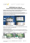
Camera Phone Flash Evaluation Board User’s Manual
Board Features
FLASH mode with adjustable voltage and current
TORCH/MOVIE mode with adjustable voltage and current
Vin and Vout indicating LED’s
On-board or External triggering
On-board or External white LED
LED and inductor current measurement ability
Undervoltage lockout (UVLO)
Boost enable/disable during flash and torch for different power architectures
Auto run for flash or torch
Quick Setup
The following jumpers should be in place J2, J5, J7, J8 and J10. Connect the positive
terminal of a single cell Lithium Ion rechargeable battery (3.3V-4.2V) to any pin on J1 and
connect the negative terminal to any pin of J3. The red LED (D1) should come on
immediately and the yellow LED (D2) should increase in brightness over a few seconds
whilst the supercapacitor charges up.
When the TORCH push button (SW1) is pressed 100mA will flow through the white LED
(D5). At 100mA the button can be held down continuously.
When the FLASH push button (SW2) is pressed 1A will flow through the white LED (D5) for
approximately 80ms. If the button is held down continuously the flash will retrigger
approximately every 2.5s. This duty cycle is imposed due to the thermal constraints of the
white LED.
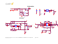
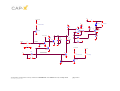
Circuit Description (refer to schematics at the end of this manual)
Input Voltage
The circuit is designed to operate from an external Li ion battery (4.2V-3.3V).
Vbat is the node connected to the battery via J1.
J1 is to be connected to battery positive terminal. Pins 1 and 2 of J1 are joined.
J3 is to be connected to battery negative terminal. Pins 1 and 2 of J3 are joined.
An undervoltage lockout (UVLO) has been included (U2B) such that when the battery voltage
drops below 3.1V the main switch (MOSFET M1) opens. It will reclose with 350mV of
hysteresis (3.45V). The 3V regulator remains operational during a UVLO.
The main reason for the UVLO is that the boost controls Vout which is the sum of the input
voltage (battery or perhaps bench top supply) plus the supercap (C1) voltage. The voltage
across the supercap is not measured. Therefore, if the input voltage was say 3V and Vout
was controlled to be 5.7V then the supercap would be at 2.7V which reduces its life. For
maximum life the supercap should be kept below 2.3V. However, the supercapacitor voltage
can be increased to 2.5V for short periods, such as while taking flash photos, without
affecting life.
Indicating LED’s
D1 is a red LED that indicates a source voltage is present and that a UVLO has not occurred.
D2 is a yellow LED and indicates that Vout is present and above approximately 5V.
All information contained herein is strictly confidential
© CAP-XX Pty Limited 2005
APPEB1006 User Manual rev1.0, 31-May-2005
page 2 of 6