1
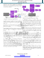
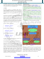
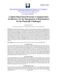
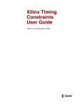
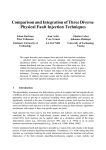
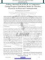
International Journal of Science and Research (IJSR)
ISSN (Online): 2319-7064
Impact Factor (2012): 3.358
Polling, Interrupts & µCOS-II: A Comparative
Timing Response Simulation Model for Wireless
Processor-to-Processor Communication
Tinotenda Zwavashe1, Dr D Vasumathi2
1
MTech Student, ECE Department, Jawaharlal Nehru Technological University, Hyderabad, AP, India
2
Professor, CSE Department, Jawaharlal Nehru Technological University, Hyderabad, AP, India
Abstract: The paper aims to analyze the timing performance characteristics of systems employing polling, interrupts and a Real Time
Operating System (RTOS). The RTOS used, specifically, is uCOS-II. The analysis incorporates a model of an Industrial system made up
of microcontrollers which communicate using Zigbee protocol and data is send and received over serial ports of the microcontrollers.
One microcontroller functions as the sensor node and the other is the master which receives values from sensor node and sends out
appropriate control commands in response to received sensor data. The performance of the master node is taken into account since all
monitoring and control is being dedicated to this master node. A physical condition of the industrial environment is sent, and in the
model we shall send real time temperature values from sensor node to master node such that when set points are exceeded then master
controller sends a command to switch ON cooling system to sensor node. The time taken from when sensor node sends an out of range
temperature value up to the time it will receive control command from master node is used to determine the time response of the system
under the three scenarios of polling, interrupts and an RTOS. Thus the analysis aims to see how polling the serial port, serial interrupts
and an RTOS affect the response, predictability and deterministic behavior of the system.
Keywords: Timing response, Interrupts, Polling, RTOS, Predictability, Zigbee, Priorities, Task Synchronization
1. Introduction
The advances in technology have seen huge strides in how
the industrial setup looks like. Traditionally we have seen
the use of cables for connecting sensor and actuating devices
to controllers. However by incorporating a Zigbee wireless
communication model whereby the Xbee communication
hardware is connected serially, system response is of prime
importance. The time taken for the data received on the
serial port to be processed and appropriate response taken
must be taken into account. With this in mind a wireless
sensor node has been designed using PIC16F877A which
reads temperature values and also contains the interface to
the actuators. Another node has been made which is the
master node using the LPC2148, which is an ARM based
microcontroller. The master node should respond to received
temperature data and give out the appropriate response. An
analysis is also done on how the response characteristic
looks like as the number of tasks to be executed by the
master node increases, that is, how this node will handle the
serial available data in an environment comprising more than
one task.
2. Existing Methods
From the searches done it seems not so much analysis has
been done on the comparison of these three scenarios. Much
attention has been put on the comparison between interrupts
and polling with a main focus being towards their
differences and the advantages/ disadvantages of each and
not the in depth timing analysis of the two. Thus we shall
give a brief overview of these forms of analysis as they are
not directly linked to the study being done in this piece of
work. In [2] a brief overview of differences between
Paper ID: 02014978
interrupts and polling and advantages of each is given.
Reference is made to the MSP430G2xxx microcontroller and
makes use of port, timer and serial interrupts. The script also
specifies how interrupts can be useful in low power
applications for waking processor from idle mode. The work
in [1] brings out a point that traditional models of interrupt
management have an incapacity to incorporate reliability and
temporal determinism which is demanded on real time
systems. The author proposes a model to integrate interrupts
and task handling. An analysis based on scheduling is done
to evaluate and distinguish the circumstances under which
the integrated model improves the traditional model.
The system in [6] addresses issues of overheads imposed by
interrupts on tasks. It illustrates how interrupts, with their
small execution times, reduce the utilization of the CPU if
they are handled at task level. The execution time of
interrupts is considered significantly less than the granularity
of the online dispatcher. The model assumed is based on
fixed release times and fixed deadlines. A task which has its
release time fulfilled can only be delayed by higher priority
task of interrupts. For analysis, interrupts have been
considered as high priority tasks and included in response
time analysis. The discussion which follows will now take an
in depth analysis of the proposed model and how simulations
are carried out to determine time response as specified in the
abstract.
3. System Model
As stated earlier on the master node consists the LPC2148
while the sensor node is controlled by the PIC16F877A. The
articles in [3] and [4] are earlier works by this author which
illustrate the concepts of processor to processor
Volume 3 Issue 7, July 2014
www.ijsr.net
Licensed Under Creative Commons Attribution CC BY
116
International Journal of Science and Research (IJSR)
ISSN (Online): 2319-7064
Impact Factor (2012): 3.358
communication. The author has borrowed these concepts and
used them in this article to establish the communication
between the PIC microcontroller and the LPC2148
microcontroller. The diagrammatic setup of the two systems
is shown in Fig 1 and Fig 2.
Figure 2: Sensor node comprising PIC16F877A
Figure 1: Master node comprising LPC2148
A. Hardware Description for LPC2148 station.
The hardware description will also illustrate how each of the
hardware components contributes to system functionality.
The LPC2148 is the central point to the functionality of the
Master node.
1) LPC2148: This is a microcontroller with an ARM7TDMI
based processor. The LPC series is manufactured by NXP
Phillips Semiconductors.
2) Xbee Module: These are the hardware components used
in data transmission and they use the Zigbee communication
architecture. Zigbee is an IEEE802.15.4 communication
interface.
3) LCD: The 20x4 LCD is used for display purposes and it is
connected close to the master node microcontroller. It shows
the updated temperature values all the time. In the timing
simulations, temperature display on the LCD has been taken
as one of the tasks which can utilize CPU time. In some
cases the task is omitted so as to present different number of
available tasks to the LPC2148.
4) UARTS: These are Universal Asynchronous
Receiver/Transmitter modules and are used for serial data
transmission. UART0 is connected to the PC for the
purposes of remote temperature display. However, just like
the LCD, the PC display task is not included in all the
simulations. Varied numbers of tasks have been used so in
some cases some tasks are exempted from the simulation.
UART1 is used to connect the Xbee modules for the purpose
of wireless data transmission between the Master Node and
Sensor Node. As such, another Xbee module is connected to
the serial port of PIC16F877A (Sensor Node).
Paper ID: 02014978
B. Hardware Description for PIC16F877A station
1) PIC16F877A: This is a medium range, 8 bit
microcontroller from Microchip Company. It has been used
here to coordinate the activities at the sensor node. It reads
temperature values, processes them and sends the values to
Master Node accordingly. It also contains the actuator
interface comprising the DC motor and associated driver.
Thus code to manipulate read temperature and to calculate
elapsed time between sending an out of range temperature
value and actuation is resident here.
2) 20x4 LCD: At the sensor node the LCD has mainly been
used for simulation purposes as a display for the number of
overflows accumulated and the residue values of the Timer1
registers. These values are in decimal notation. By
manipulation of these values the elapsed time can be easily
calculated.
3) LM35 Sensor: This is a temperature sensor and its output
is analogue in nature. Therefore the output has to be
converted to digital format and this is achieved by
connecting the sensor to an Analogue to Digital Converter
channel. The LM35 gives a linear output and output voltage
increases by 10mV for every 1oC rise in temperature and it
can measure temperatures within the range of -55 to +150oC.
4) USART: The Universal Synchronous/Asynchronous
Receiver and Transmitter is the serial module of the
PIC16F877A and is used to interconnect the Xbee module
for wireless communication with the Master Node. Some
serial interrupt is used to respond to the commands send by
the Master Node
5) L293D: The module is deigned to drive a variety of
inductive loads. Examples include DC motor, relays,
solenoids, bipolar stepper motors and other high current/high
voltage loads in positive supply applications. It functions as
a quadruple high current half H-driver. It is used in this
system to drive the DC motor.
Volume 3 Issue 7, July 2014
www.ijsr.net
Licensed Under Creative Commons Attribution CC BY
117
International Journal of Science and Research (IJSR)
ISSN (Online): 2319-7064
Impact Factor (2012): 3.358
4. Method used to Determine Elapsed Time
The method used to determine time elapsed is such that
whenever the PIC microcontroller sends data it will
immediately start a timer. Timer 1, which is a 16-bit timer, is
used and is reset to 0x0000. Timer 1 can count to 65 535 and
overflow to 0 under no other advanced settings. So if the
LPC2148 receives data and calculates that temperature is
above set point it immediately sends a command to switch
ON motor and when PIC receives this command it
immediately stops timer. PIC microcontroller is configured
for USART receive interrupt such that the first task inside
the ISR is to stop timer. The PIC microcontroller makes
calculations and number of overflows incurred and the
residues of Timer Registers are used to calculate elapsed
time, i.e. the number of overflows incurred and the final
values of TMR1H and TMR1L registers is displayed on the
20x4 LCD and these can be used to calculate elapsed time.
The delay capturing process is illustrated in Fig 3.
1) Three tasks (Polling, LCD Display, PC display via
UART0): There are 3 tasks inside infinite loop and a system
poll receives flag and runs the other tasks continuously. First
task checks if serial receive flag has been set to signify
presence of data on serial port (polling function). Second
task is for displaying temperature value on LCD. Third task
is to send temperature value to UART0 for display on PC.
Thus serial data can be available whilst controller is still
executing any one of the 3 tasks.
2) Two Tasks (Polling + PC Display via UART0): Inside an
infinite loop we have a task checking/polling to see if the
receive flag has been set. Another task displays temperature
on PC via UART0. So system sequentially goes through
these 2 tasks continually. If receive flag indicates serial data
then system goes to receive the data and checks received
value against set points and performs necessary action.
System then returns to while (1) loop and displays
temperature value received. Thus it can be seen that the
serial flag can be set while system is running the temperature
display routine and this will present a delay in serial
response.
3) Two Tasks (Polling + LCD Display): Inside an infinite
loop we have a task checking/polling to see if the receive
flag has been set. Another task displays temperature on
LCD. So system sequentially goes through these 2 tasks
continually. If receive flag indicates serial data then system
goes to receive the data and checks received value against
set points and performs necessary action. System then
returns to while (1) loop and displays temperature value
received. Thus it can be seen that the serial flag can be set
while system is running the temperature display routine and
this will present a delay in serial response.
Figure 3: Diagrammatic representation of the sequence of
events used in calculating elapsed time
4) Single Task (Polling): Single Task inside continuous loop
which polls to see if the UART1 receive flag, LSR<0>, has
been set. If flag is set then a serial receive routine is initiated.
The received value is then checked to see if it’s not outside
set limits. If it’s inside limits then received data is just
displayed on LCD and PC. If value is outside limit, then a
command is sent via UART1 to switch ON motor driving
cooling system. The value is then displayed on PC and LCD
and a warning message that temperature is above limit.
B. Interrupts:
5. System Functionality
This analysis shall check the system response to UART1
interrupt. Again varied numbers of tasks are used in the
implementation and simulation.
A. Polling
Polling method utilizes a method whereby some flag is
continually checked to see if it has satisfied some condition.
In this setup the serial receive flag (RDR: Receive Data
Ready) is continually checked to see if it is set to 1. If it is
set to 1 it signifies that the Receive Buffer has some data.
Thus here, tasks are executed sequentially in some specific
order with the polling being one of the tasks. This order is
consistent given that interrupts are disabled. We shall make
an analysis on UART1 receive flag polling where different
numbers of tasks are to be executed.
Paper ID: 02014978
1) Two Tasks (LCD Display + PC Display via UART0):
Two tasks are running inside the infinite loop and the system
should run ISR task when interrupt occurs.
2) Single Task (PC Display via UART0): Apart from
waiting for the interrupt the while (1) loop also runs the task
which displays temperature value on PC.
3) Single Task (LCD Display): Apart from waiting for the
interrupt the while (1) loop also runs the task which displays
temperature value on LCD.
Volume 3 Issue 7, July 2014
www.ijsr.net
Licensed Under Creative Commons Attribution CC BY
118
International Journal of Science and Research (IJSR)
ISSN (Online): 2319-7064
Impact Factor (2012): 3.358
4) No Task: Continuous loop with no task running. An ISR
is initiated by the presence of data on UART1. The ISR will
point to the single task for receiving serial data, responding
to temperature value received and display data.
C. RTOS
The RTOS, uCOS-II is a pre-emptive kernel which is
portable, ROMable and scalable. It has 64 priority levels of
which the highest four and lowest four are reserved for
system tasks. Thus a total of 56 user tasks can be created and
assigned priorities. The lower the number the higher the
priority.
The analysis uses three tasks which are assigned different
priorities. The three tasks are the UART receive task, LCD
Display task and the PC Display task. The focus of the
analysis is on the UART receive task which shall be given
different priorities with the time response being noted for
each case. (It should be noted that the serial task can also be
responded to using interrupts in this situation but the analysis
has limited the task to priority based response). The priorities
shall be assigned according to the following criteria.
a) Case 1: Priority Assignments
Figure 4: An overview of Semaphore operations
The model in Figure 5 shows the communication and
synchronization of the three tasks; UART receive, LDC
Display and PC Display
UART Receive – Priority 5
LCD Display – Priority 6
PC display – Priority 8
b) Case 2: Priority Assignments
UART Receive – Priority 6
LCD Display – Priority 5
PC display – Priority 8
c) Case 1: Priority Assignments
UART Receive – Priority 8
LCD Display – Priority 5
PC display – Priority 6
The three cases are simulated in hardware and the timing
response obtained is shown in Figure 8.
Task Synchronization and task communication
An inter task communication model can be used also in a
scenario like this one since data send to LCD and PC is
dependent on data received over the serial port. Task
communication objects include semaphores, mutex, message
queues, event flags and many more. In this case we will
consider a scenario whereby the display tasks will run only if
data has been received serially. Thus the UART receive task
should signal the other tasks to run only is it has received
some data. This concept shall be illustrated using
Semaphores. In uCOS-II a semaphore is considered as an OS
event and should be declared and created before being used.
Consider a semaphore called SemOne. The Figure in 4
illustrates how we can use this semaphore.
Paper ID: 02014978
Figure 5: Task Synchronization and communication using
semaphores
From Figure 5 it can be seen that unless serial data has been
received no other task will execute. LCD Display task has to
wait for SemOne to be available and the semaphore is only
available upon being posted by serial receive task after
receiving data. PC display task also waits for the semaphore,
SemTwo which is posted by the LCD display task.
Volume 3 Issue 7, July 2014
www.ijsr.net
Licensed Under Creative Commons Attribution CC BY
119
International Journal of Science and Research (IJSR)
ISSN (Online): 2319-7064
Impact Factor (2012): 3.358
6. Simulations and Results
Simulations were carried out for the three scenarios of
polling, interrupts and RTOS use. For each scenario varied
numbers of tasks were used so as to observe system response
in the presence of differing number of tasks. The diagrams
which follow show the simulation and timing analysis
results. Figures 6, 7 and 8 show the timing simulation results
for polling, interrupts and RTOS respectively.
6.1 Polling Response
Figure 6: Timing behavior for polling response for varied number of tasks
Observation:
As the number of tasks increases the unpredictability of the
system increases as shown in the diagram of Figure 6. The
time taken for the system to respond to received data
fluctuates over a wider range as compared to situations
where the microcontroller has to poll amongst fewer tasks.
With a single task (poll task), the predictability is higher
with the time response ranging between 654nS and 670nS.
With three tasks, the response varies from 660nS to 798nS
which is quite a wide range.
6.2 Interrupt Response
Figure 7: Timing behavior for interrupt driven response for varied number of tasks
Paper ID: 02014978
Volume 3 Issue 7, July 2014
www.ijsr.net
Licensed Under Creative Commons Attribution CC BY
120
International Journal of Science and Research (IJSR)
ISSN (Online): 2319-7064
Impact Factor (2012): 3.358
Observation:
It can be seen that irrespective of the number of tasks the
response of the system is more predictable for interrupts. The
system does not take into account which task is under
execution, but gives priority to the interrupt driven task and
CPU leaves whatever it is doing so that it can service the
interrupt signal.
6.3 RTOS Response
Figure 8: Timing behavior for RTOS driven response for varied task priorities
In a scenario where the task being given highest priority is
an external task which can also be signaled using interrupts,
it can be seen that the response of the system is almost
identical to that of interrupt driven response. Due to its high
priority the serial receive task is responded to in a timely
manner. However it has been seen that as the priority
rendered to the serial task is gradually decreased the time
taken to respond to serial data by the system increases and
the unpredictability of the system increases as illustrated by
Figure 8.
The use of a Real Time OS as a measure to quickly respond
to serial data has shown that the time responses of the RTOS
and that of interrupts are almost identical. Thus the question
which comes to mind is: What are the benefits of the RTOS?
An RTOS enables the assignment of priorities to tasks
irrespective of the source of the task. Not all tasks can be
driven by interrupts. In such cases a task which is internal to
the microcontroller can be assigned a high priority if need
be. The simulation on serial response based on priority has
clearly shown that the higher the priority the faster the task is
responded to. Likewise any other task is given an execution
slot depending on its priority.
7. Overall Observation
8. Conclusions and Future Scope
It has been seen that for polling response time response
widely varies as the number of tasks increases. Serial data
becomes available while processor is executing any one of
the tasks and serial data can be attended to only when the
time to poll the receive flag comes. However with a
reduction in the number of tasks, predictability increases and
time taken to respond to serial data is reduced.
This study has presented an analysis in the use of a Real
Time Operating System. Basing on this analysis the author is
undertaking an academic project which incorporates an
RTOS ported into a master node with the purpose of
monitoring and controlling an industrial setup. These timing
simulations were meant to provide a concrete basis as to
whether it is beneficial to use an operating system in the
design. The analysis has been successfully carried out for the
response to serial data. Priority assignments can serve for
fast response purposes for time critical industrial processes
since some processes can lead to disaster if not responded to
in time. It can be noted that the use of the RTOS presents a
whole lot of angles from which the analysis can be made.
Simulations can be carried out to ascertain the time taken in
Observation
With interrupts it has been noted that irrespective of the
number of tasks, serial data is responded to in the minimum
possible time. The CPU is interrupted from its current task of
execution and services the ISR. Therefore predictability is
somehow maintained inconsiderate of task count.
Paper ID: 02014978
Volume 3 Issue 7, July 2014
www.ijsr.net
Licensed Under Creative Commons Attribution CC BY
121
International Journal of Science and Research (IJSR)
ISSN (Online): 2319-7064
Impact Factor (2012): 3.358
executing each task and make calculations to see how much
a task can enter the wait state for pre- emption. This can also
be used as a benchmark to make an analysis into the
propagation delays incurred in the transmission of data over
the wireless network. This can thus be proposed as an
initiative for future work/scope into the analysis of timing
simulations
in
microcontroller
programming
and
communication. The study can also be extended into a
situation whereby various sensor nodes are controlled by the
same master node and timing analysis done to ascertain the
response of the system since an industrial setup might
comprise sensor nodes stationed at different locations. This
will on the overall result in more time critical system
performance.
experience in Computer Science and Engineering department. Her
research interests include Data Mining, Computer Networks, Web
Mining, Data Warehousing, Wireless Sensor networks and
Microcontroller Design.
References
[1] L. E. Levya-del-Fayo and P. Mejia-Alvarez, “Custom
Interrupt Management for Real Time and Embedded
System Kernels”, Proceedings of the Embedded RealTime Systems Implementation Workshop at the 25th
IEEE International Real-Time Systems Symposium
(RTSS).
[2] Aldo Briano, “MSP430 Launchpad Interrupt vs Polling”,
Texas Instruments.
[3] T. Zwavashe, “A Zigbee Based Inter-Processor
Communication Architecture for the Management of
Bedchambers for the Physically Challenged”,
International Journal of Innovative Research in Computer
and Communication Engineering, vol2, issue4, April
2014.
[4] Zwavashe, Tinotenda, and Rudo Duri. "Integrating GSM
and Zigbee Wireless Networks for Smart A2 farming
Enterprises in Zimbabwe.", International Journal of
Science and Research, Vol3, Issue6, June 2014
[5] Phillips Semiconductors, “LPC2148 User Manual
Volume 1”, 2005.
[6] J. Maki-Turja, G. Fohler and K. Sandtrom, “Towards
Efficient Analysis of Interrupts in Real Time Systems,
Proceedings of Work in progress Session, 11th Euro
micro Conference on Real Time Systems, New York.
[7] Digi International. “X-CTU Configuration and Test
Utility User’s Guide”, August 2008.
[8] Jean Labrosse, “MicroC/OS-II: The Real Time Kernel 2nd
Edition”, CMP Books, 1999.
[9] Jean. J. Labrosse, “Embedded Systems Building Blocks,
2nd Edition, Complete and Ready –to-Use Modules in
C”, 2000.
Author Profile
Tinotenda Zwavashe: Attained his B.Eng. Degree in
ECE from NUST, Zimbabwe in 2010. Currently he is
studying towards M. Tech Embedded Systems at
JNTUH, India. . He is a Harare Institute of Technology
staff development research fellow. His research
interests are in the area of Microcontroller Design, Wireless and
Sensor networks, Real Time Operating Systems and SCADA
systems.
Dr D. Vasumathi Attained her M Tech in Computer
Science before undergoing for the PHD Degree. At the
time of writing this paper, she had 14 years teaching
Paper ID: 02014978
Volume 3 Issue 7, July 2014
www.ijsr.net
Licensed Under Creative Commons Attribution CC BY
122