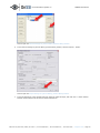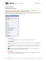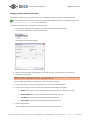
1
On-Net Surveillance Systems, Inc.
NetDVMS
Rev 6.0
IP-Based Surveillance Management System
Installation and User Manual
222 Route 59 Suite 303 | Suffern, NY 10901 | U.S.A
Phone: (845) 369-6400 | Fax: (845) 369-8711
www.onssi.com
On-Net Surveillance Systems, Inc.
NetDVMS User Manual
Table of Contents
INTRODUCTIONS ................................................................................................................................................. 6
PRODUCT OVERVIEW ................................................................................................................................................. 6
UPDATES ..................................................................................................................................................................... 7
SOFTWARE UPGRADE PLAN (SUP) .......................................................................................................................... 7
SYSTEM REQUIREMENTS ........................................................................................................................................... 7
INSTALLATION...................................................................................................................................................... 9
INSTALLING NETDVMS ............................................................................................................................................ 9
ADMINISTRATOR APPLICATION .............................................................................................................. 12
ADMINISTRATOR LOGIN WINDOW ......................................................................................................................... 12
ADMINISTRATOR WINDOW ..................................................................................................................................... 12
ADDING DEVICES .................................................................................................................................................... 13
EDITING SETTINGS FOR DEVICES .......................................................................................................................... 13
EDITING SETTINGS FOR CAMERAS ......................................................................................................................... 13
EDITING SETTINGS FOR AUDIO SOURCES............................................................................................................. 14
DISABLING/ENABLING CAMERAS AND AUDIO SOURCES ..................................................................................... 14
IMPORT OF DLKS ..................................................................................................................................................... 18
HOW TO IMPORT DEVICE LICENSE KEYS ............................................................................................................... 18
DEVICE ADMINISTRATION HOW TO ADD A DEVICE............................................................................................. 18
EDIT DEVICE SETTINGS WINDOW ......................................................................................................................... 21
CAMERA SETTINGS FOR [DEVICE NAME] WINDOW ............................................................................................. 23
CAMERA ADMINISTRATION ABOUT CAMERA ADMINISTRATION .......................................................................... 25
CAMERA SETTINGS FOR [DEVICE NAME] [CAMERA NAME] WINDOW ................................................................ 26
CONFIGURE DEVICE WINDOW ................................................................................................................................ 34
ADJUST MOTION DETECTION WINDOW ................................................................................................................. 35
COLOR WINDOW ...................................................................................................................................................... 36
DEFINE EXCLUSION REGIONS WINDOW ................................................................................................................ 37
SELECT COLOR WINDOW ........................................................................................................................................ 38
OUTPUT SETTINGS FOR [DEVICE NAME] [CAMERA NAME] WINDOW ................................................................ 39
SETUP NOTIFICATIONS ON EVENTS WINDOW....................................................................................................... 40
PTZ PRESET POSITIONS FOR [DEVICE NAME] [CAMERA NAME] WINDOW....................................................... 42
EVENT WINDOW (FOR PTZ PRESET POSITIONS ON EVENTS)............................................................................. 46
SETUP PTZ PATROLLING WINDOW ........................................................................................................................ 46
IPIX CAMERA CONFIGURATION WINDOW ............................................................................................................. 48
CAMERA NAME AND NUMBER WINDOW ................................................................................................................. 50
AUDIO SOURCE ADMINISTRATION ......................................................................................................................... 51
AUDIO DEVICE SETTINGS WINDOW ...................................................................................................................... 51
MONITOR ADMINISTRATION MONITOR MANAGER WINDOW .............................................................................. 51
RECORDING SERVER SERVICE MANAGEMENT ....................................................................................................... 54
SERVICE MANAGER WINDOW ................................................................................................................................. 54
SCHEDULING ............................................................................................................................................................ 55
CAMERA/ALERT SCHEDULER WINDOW .................................................................................................................. 55
GENERAL SETTINGS ................................................................................................................................................. 59
GENERAL SETTINGS WINDOW ................................................................................................................................ 59
CHANGE PASSWORD WINDOW ............................................................................................................................... 63
JOYSTICK SETUP WINDOW ..................................................................................................................................... 64
E-MAIL SETUP WINDOW......................................................................................................................................... 65
SMS SETTINGS WINDOW ....................................................................................................................................... 67
222 Route 59, Suite 303, Suffern, NY 10901 | Tel: 845-369-6400 | Fax: 845-369-8711 | www.onssi.com | [email protected] | Page 2
On-Net Surveillance Systems, Inc.
NetDVMS User Manual
INPUTS, EVENTS & OUTPUTS ................................................................................................................................. 69
ABOUT INPUTS, EVENTS & OUTPUTS..................................................................................................................... 69
I/O Setup............................................................................................................................................................ 70
I/O Setup Window .......................................................................................................................................... 70
Add New Event Window (for Devices Capable of Handling One Input Event Only) .............. 73
Multiple Input Events Window.................................................................................................................... 75
Add New Event Window (for Devices Capable of Handling Several Input Events)................ 76
Edit Event Window (for Editing Input Events) ..................................................................................... 77
New Timer Window......................................................................................................................................... 78
Add New Output Window ............................................................................................................................. 79
Edit Output Window ....................................................................................................................................... 80
Advanced Window........................................................................................................................................... 81
Event Buttons ................................................................................................................................................... 83
About Event Buttons ...................................................................................................................................... 83
Event Buttons Window .................................................................................................................................. 83
Add New Event Window (for Adding Event Buttons)......................................................................... 85
Edit Event Window (for Editing Event Buttons)................................................................................... 86
Generic Events Generic Events Window ............................................................................................... 88
Add New Event Window (for Specifying Generic Events) ................................................................ 89
Edit Event Window (for Editing Generic Events)................................................................................. 93
I/O Control I/O Control Window .............................................................................................................. 98
Output Settings for [Device Name] [Camera Name] Window ....................................................... 99
How to Add an Input-Based Event ......................................................................................................... 101
How to Add an Event Button .................................................................................................................... 103
How to Add a VMD Event ........................................................................................................................... 105
How to Add a Generic Event ..................................................................................................................... 107
How to test a generic event...................................................................................................................... 109
How to Add a Timer Event......................................................................................................................... 112
How to Add a Manually Controlled Output .......................................................................................... 114
How to Add a Motion-Triggered Output................................................................................................ 118
ARCHIVING ............................................................................................................................................................. 122
ABOUT ARCHIVING ................................................................................................................................................ 122
Archive Setup Window ................................................................................................................................ 124
NETMATRIX ADMINISTRATION.............................................................................................................................. 127
NetMatrix Configuration Window............................................................................................................. 127
MONITOR APPLICATION MONITOR APPLICATION .................................................................... 131
MONITOR: HOW TO ............................................................................................................................................. 136
How to Use the PTZ Menu.......................................................................................................................... 136
How to Send Live Images to NetMatrix Monitors.............................................................................. 138
VIEWER ................................................................................................................................................................... 140
USING THE VIEWER ............................................................................................................................................... 140
Browsing using the timeline browser .................................................................................................... 144
Browsing using motion view ..................................................................................................................... 145
Viewer: How to ............................................................................................................................................ 148
How to Store and Recall Views ................................................................................................................ 148
How to Print Evidence ................................................................................................................................. 149
How to Send Evidence via E-mail ........................................................................................................... 149
How to Export Video and Audio Evidence............................................................................................ 150
How to View Archived Recordings .......................................................................................................... 152
REMOTE ACCESS............................................................................................................................................... 152
222 Route 59, Suite 303, Suffern, NY 10901 | Tel: 845-369-6400 | Fax: 845-369-8711 | www.onssi.com | [email protected] | Page 3
On-Net Surveillance Systems, Inc.
NetDVMS User Manual
REMOTE ACCESS OVERVIEW................................................................................................................................. 152
PROGRAMMING DIFFERENCES: .NET OR NOT? ................................................................................................... 157
INSTALLATION DIFFERENCES ................................................................................................................................ 157
FEATURE DIFFERENCES ......................................................................................................................................... 157
IMAGE SERVER ADMINISTRATION ........................................................................................................................ 158
ImageServer Administrator Window...................................................................................................... 158
Defining Users ................................................................................................................................................ 160
Defining User Access Rights...................................................................................................................... 160
Define Local IP Ranges Window .............................................................................................................. 161
User Administration Window..................................................................................................................... 162
Define User Rights Window ....................................................................................................................... 166
NETGUARD EVS CLIENT ....................................................................................................................................... 168
NetGuard-EVS Introduction....................................................................................................................... 168
Download, Installation & Login ................................................................................................................ 170
Downloading and Installing NetGuard-EVS......................................................................................... 170
Logging in to NetGuard-EVS ..................................................................................................................... 170
Login Error Messages................................................................................................................................... 173
Selecting Language ...................................................................................................................................... 174
Views.................................................................................................................................................................. 174
Private and Shared Views .......................................................................................................................... 174
How to Create & Manage Views............................................................................................................... 175
How to Add Content to Views................................................................................................................... 179
Further Configuration .................................................................................................................................. 186
Adjusting Camera Properties .................................................................................................................... 186
Customizing Joystick Setup....................................................................................................................... 189
Assigning Custom Keyboard Shortcuts................................................................................................. 191
Selecting Language ...................................................................................................................................... 192
Using an HTML Page for Navigation in NetGuard-EVS.................................................................... 192
NetGuard-EVS Scripting ............................................................................................................................. 196
Day-to-Day Use ............................................................................................................................................. 199
Viewing Live Images .................................................................................................................................... 199
Viewing Recorded Images ......................................................................................................................... 208
Exporting Video Evidence........................................................................................................................... 217
Camera Message Texts ............................................................................................................................... 222
Using Multiple Windows .............................................................................................................................. 224
Using Standard Keyboard Shortcuts...................................................................................................... 227
LOGGING OUT OF NETGUARD-EVS..................................................................................................................... 228
NETGUARD CLIENT ................................................................................................................................................ 229
NetGuard Introduction ................................................................................................................................ 229
Downloading and Installing the NetGuard........................................................................................... 230
Accessing NetGuard ..................................................................................................................................... 230
Viewing Live Images .................................................................................................................................... 240
Point-and-Click Control ............................................................................................................................... 242
PTZ Navigation Buttons .............................................................................................................................. 242
PTZ Preset Positions..................................................................................................................................... 242
IPIX PTZ Positions......................................................................................................................................... 242
Viewing Recorded Images ......................................................................................................................... 243
Master Time Area .......................................................................................................................................... 243
Browse Buttons.............................................................................................................................................. 244
Time Sliders..................................................................................................................................................... 244
Playback Slider and Buttons ..................................................................................................................... 244
Go To Time ...................................................................................................................................................... 244
222 Route 59, Suite 303, Suffern, NY 10901 | Tel: 845-369-6400 | Fax: 845-369-8711 | www.onssi.com | [email protected] | Page 4
On-Net Surveillance Systems, Inc.
NetDVMS User Manual
Point-and-Click Control ............................................................................................................................... 245
PTZ Navigation Buttons .............................................................................................................................. 245
PTZ Preset Positions..................................................................................................................................... 245
IPIX PTZ Preset Positions........................................................................................................................... 245
Exporting Video Evidence........................................................................................................................... 246
Keyboard Shortcuts...................................................................................................................................... 248
Using an HTML Page for Navigation in NetGuard.............................................................................. 249
Logging Out of NetGuard ........................................................................................................................... 252
NETPDA/NETCELL CLIENT & SERVER ................................................................................................................ 253
NetPDA/NetCell Client & Server Introduction..................................................................................... 253
Installing & Configuring the NetPDA/NetCell Server ....................................................................... 254
NetPDA Installation ...................................................................................................................................... 257
Installing & Configuring the NetPDA/NetCell Client ......................................................................... 260
Using the NetPDA/NetCell Client ............................................................................................................. 263
Finding Recordings from a Specific Time and Date.......................................................................... 268
Finding Recordings from a Specific Event............................................................................................ 268
Returning to the Camera List Page ........................................................................................................ 269
WEB AND REALTIME FEED SERVERS .................................................................................................................... 270
Web Server Setup......................................................................................................................................... 271
User Administration...................................................................................................................................... 272
Testing the Web Server Configuration.................................................................................................. 273
Starting the Web Server............................................................................................................................. 274
Stopping the Web Server ........................................................................................................................... 274
Shutting Down the Web Server ............................................................................................................... 274
Starting the Realtime Feed Server ......................................................................................................... 275
Stopping the Realtime Feed Server ....................................................................................................... 275
Shutting Down the Realtime Feed Server............................................................................................ 275
Remote Access through Web and Realtime Feed Servers............................................................. 276
NETMATRIX MONITOR.................................................................................................................................. 281
NetMatrix Monitor Introduction................................................................................................................ 281
Installing the NetMatrix Monitor Application....................................................................................... 281
Configuring the NetMatrix Monitor Application .................................................................................. 282
Day-to-Day Use of the NetMatrix Monitor Application.................................................................... 287
Controlling NetMatrix Monitors from a HTML Page .......................................................................... 291
LOGGING .............................................................................................................................................................. 293
ADMINISTRATOR LOG FILES ................................................................................................................................. 293
MONITOR APPLICATION LOG FILES ...................................................................................................................... 293
RECORDING SERVER SERVICE LOG FILES ........................................................................................................... 293
EVENT LOG FILES .................................................................................................................................................. 293
IMAGE SERVER LOG FILES .................................................................................................................................... 294
IMAGE SERVER AUDIT LOG FILES ........................................................................................................................ 294
EXPORT LOG FILES ................................................................................................................................................ 294
WEB SERVER LOG FILES ....................................................................................................................................... 294
REMOVAL.............................................................................................................................................................. 296
Removing
Removing
Removing
Removing
NetGuard-EVS ........................................................................................................................... 296
NetGuard..................................................................................................................................... 296
the NetPDA/NetCell Software.............................................................................................. 296
the NetMatrix Monitor Application ..................................................................................... 297
COPYRIGHT, TRADEMARKS, ETC. ........................................................................................................... 298
222 Route 59, Suite 303, Suffern, NY 10901 | Tel: 845-369-6400 | Fax: 845-369-8711 | www.onssi.com | [email protected] | Page 5
On-Net Surveillance Systems, Inc.
NetDVMS User Manual
Introductions
Product Overview
With the purchase of NetDVMS you have chosen the right product for medium to large installations wanting robust
surveillance software with full functionality for advanced management, flexible scheduling, fast searching and
analysis.
NetDVMS is:
•
Compatible with a wide range of different IP video products from the leading manufacturers, so you choose
the hardware you want—in combinations too
•
Dependable; with robust and stable performance proven in operation on thousands of cameras worldwide
•
Flexible; with remote access features that let you use the surveillance system from any place and at any
time
•
Scalable; with open architecture based on IP technology with ongoing development and regular updates,
which gives you long-term returns on your surveillance investment
•
Future-safe; the IP network approach is the foundation for tomorrow—available today
NetDVMS consists of a number of components, each targeted at specific tasks and user types:
•
The Administrator: The main application used by surveillance system administrators for configuring the
NetDVMS surveillance system server, upon installation or whenever configuration adjustments are
required, e.g. when adding new cameras or users to the system.
•
The Recording Server: A vital part of the surveillance system; recordings are only transferred to NetDVMS
while the recording server is running. The recording server may be installed in two ways: Either as an
application (the Monitor application) or as a service (the Recording Server service), See Installing the
Software for more information about the installation differences.
•
The Image Server: Handles access to the surveillance system for remote users logging in with the
NetGuard, NetGuard-EVS, or NetPDA/NetCell. The Image Server itself does not require separate hardware;
it runs as a service on the surveillance system server. Surveillance system administrators handle Image
Server configuration, including remote users' access rights, through the Image Server Administrator
application.
•
The NetGuard and NetGuard-EVS: Choice of two types of remote access clients, each providing users with
intuitive remote access to the surveillance system. The NetGuard and NetGuard-EVS let users view live
images, play back recorded images, activate outputs, print and export evidence, etc. The NetGuard lets
users view live images, play back recorded images, activate outputs, print and export evidence, etc. The
NetGuard can be downloaded from the surveillance system server and installed locally on remote users'
PCs, or the users can access it straight from the surveillance system server through an Internet Explorer
browser. The extra feature-rich NetGuard-EVS should always be downloaded and installed on remote users'
PCs.
•
The Web Server and Realtime Feed Server: Simple alternatives to the Image Server/NetGuard/NetGuardEVS for providing remote access to the surveillance system, the Web Server and Realtime Feed Server let
system administrators manage remote access. Remote users access the Web Server and Realtime Feed
Server through an Internet Explorer browser.
222 Route 59, Suite 303, Suffern, NY 10901 | Tel: 845-369-6400 | Fax: 845-369-8711 | www.onssi.com | [email protected] | Page 6
On-Net Surveillance Systems, Inc.
NetDVMS User Manual
Updates
OnSSI regularly releases service updates for its products, offering improved functionality and support for new
devices.
If you are an OnSSI system administrator, it is recommended that you check the OnSSI website www.onssi.com for
updates at regular intervals in order to make sure you are using the most recent version of OnSSI.
Software Upgrade Plan (SUP)
As the cornerstone of its support to customers, OnSSI offers a Software Upgrade Plan (SUP). The purpose of the
SUP is to provide you with lower cost alternative to standard Software upgrades.
SUP coverage can easily be purchased together with most new OnSSI products, but cannot be purchased as an addon to a previously purchased product.
During the period covered by the SUP, customers are entitled to receive all generally-released new versions of their
OnSSI software, including both interim and major releases, changes, service packs and any patches for the product.
Having a valid SUP may easily lead to measurable savings for your organization: The standard cost of a product
upgrade (for example from version X.1 to X.2) is normally 35% of the full product’s recommended retail price for a
single upgrade; depending on the product, the whole SUP cost per year is much lower then the above single
software upgrade, and you will be entitle to receive as many upgraded released in the covered period.
System Requirements
The following are minimum system requirements for running NetDVMS and associated applications:
•
Surveillance System Server
Operating System
Microsoft Windows 2000 Professional, Windows 2000 Server and Advanced
Server, Windows XP Professional (32 and 64 bit) or Windows Server 2003 (32
and 64 bit)
CPU
Intel P4 or higher (Xeon recommended), minimum 2.4 GHz.
RAM
Minimum 1 GB.
Network
Ethernet, 1 Gbit recommended.
Graphics Card
AGP or PCI-Express, minimum 1024×768, 16 bit colors.
Hard Disk Type
E-IDE, PATA, SATA, SCSI, SAS (7200 rpm or faster).
Hard Disk Space
80 GB free (depends on number of cameras and recording settings)
Software
DirectX 9.0 or newer required to run the live view Monitor application.
To run the NetPDA the following is required: Internet Information Services (IIS)
5.0 or later as well as Microsoft .Net Framework 1.1.
Tip: To check which DirectX version is installed on a computer, click Start, select Run..., and type
dxdiag. When you click OK, the DirectX Diagnostic Tool window will open; version information is displayed
near the bottom of its System tab. Should the server require a DirectX update, the latest versions of
DirectX are available from http://www.microsoft.com/downloads/
Tip: Information about how to verify/install Microsoft .Net Framework and IIS versions is available in
Installing & Configuring the NetPDA.
222 Route 59, Suite 303, Suffern, NY 10901 | Tel: 845-369-6400 | Fax: 845-369-8711 | www.onssi.com | [email protected] | Page 7
On-Net Surveillance Systems, Inc.
•
•
NetGuard-EVS
NetGuard
•
NetPDA/NetCell Server
NetDVMS User Manual
The NetPDA/NetCell Server is typically installed on the surveillance system server; see the system
requirements for the surveillance system server.
Note, however, that to run the NetPDA/NetCell Server the following is also required on the surveillance
system server:
•
•
Internet Information Services (IIS) 5.0 or later
Microsoft .Net Framework 1.1.
Note that later versions of. Net Framework may also be present on the server. If .Net Framework 1.1 as
well as one or more later versions are present on the server, Windows' default settings may cause a later
.Net Framework version to be used instead of .Net Framework 1.1. To verify/change which .Net Framework
version is used, do the following:
1.
2.
3.
4.
Click Start and select Control Panel.
Click Administrative Tools.
Click Internet Information Services.
In the Internet Information Services window's left pane, locate and right-click the Default Web
Site item:
Example only; content on
your server may be different
5.
6.
7.
In the resulting menu, select Properties. This will open the Default Web Site Properties dialog.
Select the dialog's ASP.NET tab. The .Net Framework in use will be indicated in the ASP.NET
version field.
If required, change the ASP.NET version to 1.1.4322:
Example only.
8.
9.
Click OK.
Close the Internet Information Services and Administrative Tools windows if still open.
222 Route 59, Suite 303, Suffern, NY 10901 | Tel: 845-369-6400 | Fax: 845-369-8711 | www.onssi.com | [email protected] | Page 8
On-Net Surveillance Systems, Inc.
•
•
NetDVMS User Manual
NetPDA/NetCell Client
Operating System
Microsoft Windows Pocket PC 2003/2003 SE/Mobile 5.0.
CPU
Intel StrongARM or 100% compatible.
RAM
Minimum 32 MB.
Network
Ethernet, 256 Kbit or higher recommended.
Graphics Card
Minimum 320×200, 16 bit colors.
NetMatrix Monitor
Operating System
Microsoft Windows 2000 Professional, Windows 2000 Server and Advanced
Server, Windows XP Professional (32 and 64 bit) or Windows Server 2003 (32
and 64 bit)
CPU
Intel P3 or higher, minimum 1.0 GHz.
RAM
Minimum 256 MB.
Network
Ethernet, 100 Mbit or higher recommended.
Graphics Card
AGP or PCI-Express, minimum 1024×768, 16 bit colors.
Hard Disk Space
50 MB free.
Installation
Installing NetDVMS
Note: Read the End User License Agreement on the Product License Sheet (enclosed with the software CD) before
installing NetDVMS.
To install NetDVMS, do the following:
Prerequisites: Shut down any existing software running, including any Web and Realtime Feed Servers. If
upgrading, it is highly recommended that you remove any previous versions before upgrading.
1.
Insert the NetDVMS software CD, wait for a short while, select required language, then click the Install
NetDVMS link.
Alternatively, if you are installing a version downloaded from the internet, run the file NetDVMS.exe from the
location you have saved it to.
Tip: Depending on your security settings, you may receive one or more security warnings (Do you want
to run or save this file?, Do you want to run this software?). When this is the case, click the Run button.
2.
When the installation wizard starts, click Next to continue the installation.
3.
Read and accept the End User License Agreement.
4.
Select required language version, and click Next.
5.
Select the Licensed Version option, and click Next.
6.
Type your Software License Code, as listed on your Product License Sheet.
222 Route 59, Suite 303, Suffern, NY 10901 | Tel: 845-369-6400 | Fax: 845-369-8711 | www.onssi.com | [email protected] | Page 9
On-Net Surveillance Systems, Inc.
NetDVMS User Manual
You have the option of installing the software for anyone using the computer, or for yourself only. If
installing for yourself only, bear in mind that if your login is not an administrator login, you will need to
change the login name for the Image Server service so it matches your own login, i.e. uses the same user
name and password.
When ready, click Next.
7.
Select how NetDVMS's recording server should run.
The recording server is a vital part of the surveillance system; it is used for recording and displaying
images from connected cameras. You can install the recording server either as a Windows service or as an
application:
•
If you install the recording server as a Windows service, it will automatically load whenever the
NetDVMS server is started; it will not require any further login or similar in order to run. However,
when the recording server runs as a service, you will not automatically have a local client
application for viewing live and recorded video on the surveillance system server; instead you will
have to connect to the surveillance system server through one of NetDVMS's feature-rich remote
access clients.
You typically select this option if your surveillance system server is placed in a separate server
room or a similar location to which regular access is not practical.
•
If you install the recording server as an application, the application (called the Monitor
application) will be available on the surveillance system server for viewing of live and recorded
images. However, the Monitor application will require a local login in order to run. With this
solution, images are only transferred to the surveillance system server while the Monitor
application is running; the Monitor application must therefore run whenever you want to be able
to record or view live images from cameras on your surveillance system.
You typically select this option if you intend to view live and recorded video directly on your
surveillance system server, for example when the server is placed in your control room or a
similar location to which you and trusted users have regular access. With this solution, NetDVMS's
remote access clients can of course still be used for accessing the surveillance system server from
remote locations.
When ready, click Next.
222 Route 59, Suite 303, Suffern, NY 10901 | Tel: 845-369-6400 | Fax: 845-369-8711 | www.onssi.com | [email protected] | Page 10
On-Net Surveillance Systems, Inc.
8.
NetDVMS User Manual
Select required language for the NetGuard, one of NetDVMS's remote access clients.
Tip: You do not have to select a language version for the NetGuard-EVS during installation; the
NetGuard-EVS automatically comes with several languages, and users select their individual language
versions themselves.
When ready, click Next.
9.
Follow the next few simple steps in the installation wizard until you are asked to select the setup type that
best suits your needs:
•
If you want shortcuts to NetDVMS's various applications placed on the desktop automatically,
keep Add shortcut to desktop selected.
•
Available only when the recording server has been installed as an application (the Monitor
application): If you want NetDVMS's Web Server and RealtimeFeed Server (a very basic remote
access solution, recommended only if remote users connect through very slow connections) to run
automatically each time the computer loads Windows, select Add Web Servers to Startup group.
When ready, click Next.
10. Click Finish on the last step to complete the installation.
Tip: For descriptions of how to install NetDVMS's various remote access clients, see information about each
individual client. A good starting point is the Remote Access Overview. Installation of the NetMatrix Monitor
software is covered in Installing the NetMatrix Software.
222 Route 59, Suite 303, Suffern, NY 10901 | Tel: 845-369-6400 | Fax: 845-369-8711 | www.onssi.com | [email protected] | Page 11
On-Net Surveillance Systems, Inc.
NetDVMS User Manual
Administrator Application
Administrator Login Window
For users without administrator rights, access to certain features in NetDVMS may in some organizations have been
restricted.
When this is the case, you will be asked to specify the administrator password in the Administrator Login window in
order to get access to the restricted features.
The Administrator Login window
You will only be asked to specify the administrator password in three situations:
•
When you open the Administrator application, by selecting it from Windows' Start menu or by clicking the
Administrator shortcut on the desktop. This will only be the case when access to the Administrator
application has been password-protected.
•
When you click the Admin Login button to access the Administrator from the Monitor application.
•
When access to particular features, such as control of PTZ (Pan/Tilt/Zoom) cameras in the Monitor
application, has been restricted to administrators only.
Administrator Window
Note: Access to features in the Administrator application, including those described in the following, may require
administrator rights.
The Administrator window, the main window in the Administrator application, is used by the surveillance system
administrator for configuring NetDVMS upon installation or whenever configuration adjustments are required, e.g.
when adding new cameras to the system.
Access: You access the Administrator application by selecting it from Window's Start menu
or by clicking the Administrator shortcut on the desktop. If the Monitor application is installed,
and access from the Monitor application is enabled, the Administrator application may also be
accessed from the Monitor application. Access to the Administrator application may be password
protected, in which case you will be asked to provide the administrator password in the
Administrator Login window.
Administrator
desktop
shortcut
The Administrator window features a Device Manager section as well as a number of buttons providing access to
configuration:
•
Device Manager Section
The Device Manager section—located in the middle of the Administrator window—lists all added devices
and attached cameras. The Device Manager section thus provides you with an overview of your
surveillance system.
222 Route 59, Suite 303, Suffern, NY 10901 | Tel: 845-369-6400 | Fax: 845-369-8711 | www.onssi.com | [email protected] | Page 12
On-Net Surveillance Systems, Inc.
NetDVMS User Manual
Detail from the Administrator window's Device Manager section—two
devices have been added; the first device has a single camera
attached, whereas the second device has four cameras attached
Until you have added devices, the Device Manager section will be empty.
Adding Devices
You add devices through an intuitive Device Setup Wizard, available by clicking the Administrator window’s
Add Device button (see also How to Add a Device).
When devices have been added, they will be listed in the Device Manager section. Clicking the plus sign
next to a device in the Device Manager section will list cameras attached to the device.
Editing Settings for Devices
To edit settings for a device listed in the Device Manager section, select the device, then click the Edit
device... button to open the Edit device settings window.
Editing Settings for Cameras
To edit the settings for a camera listed in the Device Manager section, click the plus sign
next to the
device to which the camera is attached, select the required camera, then click the Settings button to open
the Camera Settings for [Device name] [Camera Name] window.
Renaming a Camera
To rename a camera, right-click the camera name in question, then select Edit from the menu that
appears:
This will open the Camera Name and Number window, in which you are able to overwrite the existing
camera name with a new one.
Assigning Shortcut Numbers to Cameras
Users of NetGuard-EVS can take advantage of a range of keyboard shortcuts, some of which let the users
toggle between viewing different cameras. Such keyboard shortcuts include numbers, which are used to
identify each camera. These camera shortcut numbers are specified in the Administrator.
To assign a shortcut number to a camera, right-click the camera name in question, then select Edit from
the menu that appears:
222 Route 59, Suite 303, Suffern, NY 10901 | Tel: 845-369-6400 | Fax: 845-369-8711 | www.onssi.com | [email protected] | Page 13
On-Net Surveillance Systems, Inc.
NetDVMS User Manual
This will open the Camera Name and Number window, in which you are able to specify a shortcut number
to be used with the camera.
Note: Camera shortcut numbers are only used in the NetGuard-EVS. In other applications, such as the
Monitor or the NetGuard, the camera shortcuts cannot be used.
Tip: More information about using keyboard shortcuts in the NetGuard-EVS is available in Using
Standard Keyboard Shortcuts.
Editing Settings for Audio Sources
To edit the settings for an audio source listed in the Device Manager section, click the plus sign
next to
the device to which the audio source is attached, select the required camera, then click the Settings button
to open the Audio Device Settings window.
Disabling/Enabling Cameras and Audio Sources
Individual cameras and audio sources listed in the Device Manager section are by default enabled, meaning
that video from cameras and audio from attached microphones is by default transferred to NetDVMS—
provided that the cameras are marked as online in the Camera/Alert Scheduler Window (also default).
If required, you can disable individual cameras and audio sources listed in the Device Manager section.
When a camera or audio source is disabled, no images/audio will be transferred from the camera/audio
source to NetDVMS.
Note: If the Monitor application is installed and the camera in question (including any attached
microphones) is included in the Monitor application (configured in the Monitor Manager window), the
camera/audio source cannot be disabled. When this is the case, remove the camera from the Monitor
Manager window's layout before disabling the camera.
To disable a camera or audio source, right-click the required camera or audio source in the Device Manager
section, then select Disable:
When a camera or audio source is disabled, it will be indicated as follows:
To enable a previously disabled camera or audio source, simply right-click the required camera or audio
source in the Device Manager section, then select Enable:
Tip: Individual cameras can also be disabled/enabled in the Camera Settings for [Device Name]
[Camera Name] Window. Individual audio sources can also be disabled/enabled in the Audio Device
Settings Window.
222 Route 59, Suite 303, Suffern, NY 10901 | Tel: 845-369-6400 | Fax: 845-369-8711 | www.onssi.com | [email protected] | Page 14
On-Net Surveillance Systems, Inc.
•
NetDVMS User Manual
Administrator Window's Buttons
The Administrator window features the following buttons:
Button
Monitor
Manager...
Description
Installation-dependent feature:
- or -
The Monitor Manager button is available only when the recording server has been
installed as an application (the Monitor application).
Recorder
Manager...
The Recorder Manager button is available only when the recording server has
been installed as a service (the Recording Server service).
See Installing the Software for more information about the installation
differences.
•
The Monitor Manager button opens the Monitor Manager window, in
which you specify which cameras should record and display images in
the Monitor application. It also lets you configure the layout of the
Monitor application.
•
The Recorder Manager button opens the small Recorder Manager
window, which lets you pause/resume the Recording Server service.
Pausing the service is necessary in order to access some features, for
example configuration of PTZ (Pan/Tilt/Zoom) cameras.
IMPORTANT: While the service is paused, no video or audio will be
recorded.
Scheduler...
Opens the Camera/Alert Scheduler window, in which you specify online periods
for each camera.
You are also able to specify if cameras should go online when specific events
occur (e.g. when a door is opened), and if e-mail, SMS or sound alerts should be
used if motion is detected during specific periods of time (e.g. during working
hours).
If using PTZ cameras with patrolling, you are furthermore able to specify if a
patrol scheme should be used during specific periods of time.
Tip: By default, all cameras are online at all times. You will only need to
modify scheduler settings if you require cameras to be online only at specific
times or events, or if you want to use specific alerts or a PTZ patrol scheme.
General
Settings...
Opens the General Settings window, in which you are able to specify a number of
settings related to:
•
Administrator password
•
User rights
•
PTZ patrolling pause time out (if using PTZ cameras with patrolling)
•
Joystick setup for PTZ cameras
•
E-mail settings (for alerts sent via e-mail)
•
SMS settings (for alerts sent via SMS)
•
Log file settings
•
Event recording settings
•
Other advanced settings, such as the ability to disable screen update in
222 Route 59, Suite 303, Suffern, NY 10901 | Tel: 845-369-6400 | Fax: 845-369-8711 | www.onssi.com | [email protected] | Page 15
On-Net Surveillance Systems, Inc.
NetDVMS User Manual
order to minimize CPU usage
Installation-dependent feature: Note that some of the settings are only
available when the recording server has been installed as an application (the
Monitor application). If the recording server has been installed as a service (the
Recording Server service), some of the features are not relevant. See Installing
the Software for more information about the installation differences.
Archive Setup...
Opens the Archive setup window, in which you specify NetDVMS's archiving
settings.
Archiving lets you keep recordings for as long as required, limited only be the
available hardware storage capacity.
Import DLKs...
Lets you import all required Device License Keys (DLKs) in one go, thus avoiding
the need to specify each DLK manually when adding devices.
See also How to Import Device License Keys.
Matrix...
NetMatrix...
Lets you access NetMatrix configuration. NetMatrix is an integrated product for
forcing video from any camera to any monitor on a network operating with
NetDVMS.
Not applicable.
NetTransact...
Note: The NetTransact button is only available if you are using OnSSI's
NetTransact (add-on product that handles loss prevention through video evidence
combined with time-linked POS or ATM transaction data) with NetDVMS. If the
recording server has been installed as a service (the Recording Server service)
rather than as an application (the Monitor application), use of NetTransact
versions earlier than 2.1 is not supported.
Lets you access NetTransact configuration.
Add Device...
Starts the Device Setup Wizard, which guides you through the process of adding
a new device.
See also How to Add a Device.
Edit Device...
When you have selected a device in the Administrator window's Device Manager
section, clicking the Edit Device... button lets you edit settings for the selected
device in the Edit device settings window.
Remove Device
Lets you remove a device selected in the Administrator window's Device Manager
section.
In order to prevent accidental removal of devices, you will be asked to confirm
that you want to remove the device.
Settings...
Lets you specify settings for a selected camera or audio source:
•
Cameras: When you have selected a camera in the Administrator
window's Device Manager section, clicking the Settings button will open
the Camera Settings for [Device Name] [Camera Name]... window, in
which you specify camera settings.
•
Audio sources: When you have selected an audio source in the
Administrator window's Device Manager section, clicking the Settings
button will open the Audio Device Settings window, in which you can
222 Route 59, Suite 303, Suffern, NY 10901 | Tel: 845-369-6400 | Fax: 845-369-8711 | www.onssi.com | [email protected] | Page 16
On-Net Surveillance Systems, Inc.
NetDVMS User Manual
enable/disable the audio source and change its name if required.
I/O Setup...
Opens the I/O Setup window, in which you are able to define events based on
input events (for example when a door sensor detects that a door is opened) and
VMD (Video Motion Detection). The I/O Setup window also lets you specify output
(e.g. a siren).
When defined, events can be used for a variety of purposes. For example, an
input event can be used for triggering output, for starting a particular camera,
and for triggering that an e-mail or SMS message is sent to a particular user,
notifying the user of the recorded event.
See also the description of the I/O Control... button.
Event Buttons...
Opens the Event Buttons window, in which you are able to define events for use
on event buttons.
Event buttons can used in the Monitor application and NetGuard-EVS for manually
triggering events.
Generic
Events...
Opens the Generic Events window, in which you are able to define events based
on input from external sources using the TCP and UDP protocols.
I/O Control...
Opens the I/O Control window, in which you are able to attach outputs to input
events.
This way you can, for example, define that a siren should sound when a sensor
detects that a door is opened.
Exit
Closes the Administrator application.
Tip: Clicking the icon in the left corner of the Administrator window's title bar, gives you access to a small menu.
Selecting About Adm ... from the menu will display a dialog with your system's version number and software license
code; this is valuable information, should you ever need to contact product support.
222 Route 59, Suite 303, Suffern, NY 10901 | Tel: 845-369-6400 | Fax: 845-369-8711 | www.onssi.com | [email protected] | Page 17
On-Net Surveillance Systems, Inc.
NetDVMS User Manual
Import of DLKs
How to Import Device License Keys
Note: Access to features in the Administrator application, including those described in the following, may require
administrator rights.
You must have a Device License Key (DLK) for every device (IP network camera or IP video server) installed on
your NetDVMS surveillance system.
Remember that you are allowed to install and use only the number of cameras listed on your organization's license
sheet; regardless of you number of available DLKs. For example, a fully used four-port video server counts as four
cameras even though the cameras are connected through a single device—therefore a fully used four-port video
server will use four licenses.
System administrators obtain DLKs as part of the software registration process.
You are able to specify each DLK manually when adding a device through the Device Setup Wizard, available by
clicking the Add Device... button in the Administrator window. However, you can avoid having to specify each DLK
manually by using the following procedure to import all received DLKs into NetDVMS in one go:
Prerequisites: The DLKs, received in a .dlk file, must have been saved at a location accessible by the surveillance
server, for example on a network drive or on a USB stick.
1.
Open the Administrator window.
2.
In the Administrator window, click the Import DLKs... button.
3.
Browse to the location at which you have saved the received .dlk file.
Select the file, and click Open.
All DLKs are now automatically imported, and the relevant DLK will automatically appear when you add a
device through the Device Setup Wizard.
Device Administration
How to Add a Device
Note: Access to features in the Administrator application, including those described in the following, may require
administrator rights.
In NetDVMS you add devices (IP video camera devices or IP video server devices) rather than actual cameras. This
is because devices have their own IP addresses or host names. Being IP-based, NetDVMS primarily identifies units
on the surveillance system based on their IP addresses or host names.
Even though each device has its own IP address or host name, several cameras can be attached to a single device
and thus share the same IP address or host name. This is typically the case with cameras attached to video server
devices.
You can of course configure and use each camera individually, even when several cameras are attached to a single
device.
In addition to IP video camera devices and IP video server devices it is possible to add a number of dedicated I/O
(input/output) devices to NetDVMS. When such I/O devices are added, they can be used in events-based system
setup in the same way as a camera. For more information about using I/O devices, see Using Dedicated I/O
Devices. For information about which I/O devices are supported, refer to the release note.
222 Route 59, Suite 303, Suffern, NY 10901 | Tel: 845-369-6400 | Fax: 845-369-8711 | www.onssi.com | [email protected] | Page 18
On-Net Surveillance Systems, Inc.
NetDVMS User Manual
Once a device is added in NetDVMS, any cameras attached to the device are automatically recognized by the
software, and listed in the Administrator window's Device Manager section:
Detail from the Administrator window's Device Manager section—two
devices have been added; the first device has a single camera
attached, whereas the second device has four cameras attached
To add a device, use the following procedure:
Prerequisites: You must have configured IP address, password, etc. on the device itself, as described by the
manufacturer.
1.
Open the Administrator window.
2.
In the Administrator window, click the Add Device... button.
This will start the Device Setup Wizard.
3.
On the first step of the wizard, identify the required device, either by
•
Typing the IP address of the device.
press SPACE on your keyboard.
Tip: To jump to the next IP address segment in the field,
- or -
•
Typing the DNS host name of the device. This requires that you select the Use DNS host names box
Specifying the IP address of a device
Note: By default, HTTP port 80 and FTP port 21 will be used for the device. If the device you are adding
uses other port numbers, click the Port Setup button and specify required port numbers. The need for
specifying different ports may often apply if the device is located behind a NAT-enabled router or a firewall.
When this is the case, also remember to configure the router/firewall so it maps the ports and IP address
used by the device.
When ready, click Next to go to the second step of the wizard.
4.
If a password is used for the device, type the password for the device's administrator account (called an
“admin” or “"root” account on some devices).
Leave the Autodetect Device option selected.
Click Next.
222 Route 59, Suite 303, Suffern, NY 10901 | Tel: 845-369-6400 | Fax: 845-369-8711 | www.onssi.com | [email protected] | Page 19
On-Net Surveillance Systems, Inc.
5.
NetDVMS User Manual
When the device has been detected, type the Device License Key (DLK) for the device in the DLK field.
Specifying DLK for the device
Tip: If you have imported DLKs (see How to Import Device License Keys), the DLK field will already be
filled with the DLK for the device.
Click Next.
6.
Assign a unique and descriptive name to the device.
Upon completion of the wizard, the name will be used when listing devices and associated cameras in the
Administrator window's Device Manager section.
The name may, for example, refer to the physical location of the camera(s) attached to the device.
Assigning a name to the device
Tip: You may click the Camera Setup button to access the Camera Settings for … window, in which you
are able to specify certain settings related to camera name and PTZ control. The latter requires that the
camera is a PTZ (Pan/tilt/Zoom) camera.
7.
Click Finish.
8.
The device will be listed in the Administrator window's Device Manager section.
To view a list of cameras attached to the device, click the plus sign
next to the device name.
Tip: Cameras are listed for each device with default names, such as 'Camera 1,' etc. If you want to
change the name of a camera, right-click the camera name in question, then select Edit from the menu
that appears.
Tip: Individual cameras listed in the Device Manager section are by default enabled, meaning that images
from the cameras are by default transferred to NetDVMS—provided that the cameras are marked as online
in the Camera/Alert Scheduler Window (also default). If required, you can disable a camera listed in the
Device Manager section by right-clicking the name of the camera in question. See more information under
Administrator window.
222 Route 59, Suite 303, Suffern, NY 10901 | Tel: 845-369-6400 | Fax: 845-369-8711 | www.onssi.com | [email protected] | Page 20
On-Net Surveillance Systems, Inc.
NetDVMS User Manual
Edit Device Settings Window
Note: Access to features in the Administrator application, including those described in the following, may require
administrator rights.
The Edit device settings window lets you edit the settings of an already installed device.
The Edit device settings window
Access: To access the Edit device settings window, select the required device in the Administrator window's
Device Manager section, and click the Edit Device... button.
The Edit device settings window is divided into two sections:
•
Identify Video Device Section
The Identify Video Device section contains the following fields, buttons, etc.:
Field, Button, ...
Description
Device Type
Select required device type from list.
Tip: NetDVMS is able to automatically detect device type as well as serial
number, provided the IP address/hostname and password of the device have
been specified in the IP-address/DNS Host Name and Root Password fields:
Simply click the Detect Device button to auto-detect device type and serial
number.
Detect Device
Click button to auto-detect device type and serial number.
Note: Use of the auto-detect feature requires that the IP address and password
of the device have been specified in the IP-address and Root Password fields.
Device Name
Name used to identify the device.
Tip: To enable easy identification of devices, it is often a good idea to use a
device name that refers to the physical area covered by the cameras attached to
the device (examples: Reception Area, Car Park B, Entrance Door, ...).
Note: Device names must be unique; you cannot use the same name for several
devices.
222 Route 59, Suite 303, Suffern, NY 10901 | Tel: 845-369-6400 | Fax: 845-369-8711 | www.onssi.com | [email protected] | Page 21
On-Net Surveillance Systems, Inc.
Camera
Settings...
NetDVMS User Manual
Opens the Camera Settings for [Device Name] window, in which you are able to
specify a number of settings for cameras attached to the device, including:
•
Port through which PTZ (Pan/Tilt/Zoom) cameras are controlled
•
Camera names, types, and ports
Note: The number of settings available in the Camera Settings for [Device Name]
window may be limited if cameras are not PTZ cameras or connected to a video
server device.
Device Serial
Number
Serial number of device; usually identical to the 12-character MAC address of the
device (example: 0123456789AF).
Tip: NetDVMS is able to automatically detect serial number as well as device
type, provided the IP address/host name and password of the device have been
specified in the IP-address/DNS Host Name and Root Password fields: Simply
click the Detect Device button to auto-detect device type and serial number.
Device License
Key
A 16-character license key (DLK) for the device, obtained when registering the
software.
Enable iPIX
Enables the use of IPIX, a technology that allows viewing of 360-degree
panoramic images.
Note: Use of the IPIX technology requires either a dedicated IPIX camera or a
regular camera equipped with a special IPIX camera lens for which a special IPIX
license key is required. If the device in question is for a dedicated IPIX camera,
the check box is selected by default, and you do not have to enter an IPIX license
key in the neighboring field.
iPIX License
Key
License key for using the IPIX technology, obtained when registering the
software.
Note: This information is only required if the Enable iPIX check box is selected
manually.
•
Network Settings for Video Device Section
The Network Settings for Video Device section contains the following fields:
Field
Description
IP-address
IP address or DNS host name of the device in question.
-orDNS Host Name
Note: If Use DNS host name check box is selected, the name of the IP-address
field changes to DNS/Host Name in order to accommodate a DNS host name
rather than an IP address.
Use DNS host
name
By selecting the check box you are able to use a DNS host name for identifying
the device instead of using the device's IP address.
When check box is selected, the IP-address field changes its name to DNS/Host
Name, ready to accommodate a DNS host name rather than an IP address.
Default Http
Port
When selected, HTTP traffic to the device will go through the default port, port
80.
If you want to use another port for HTTP traffic to the device, clear the check box,
and specify required port number in the field to the left of the check box.
222 Route 59, Suite 303, Suffern, NY 10901 | Tel: 845-369-6400 | Fax: 845-369-8711 | www.onssi.com | [email protected] | Page 22
On-Net Surveillance Systems, Inc.
Default Ftp Port
NetDVMS User Manual
When selected, FTP traffic to the device will go through the default port, port 21.
If you want to use another port for FTP traffic to the device, clear the check box,
and specify required port number in the field to the left of the check box.
Root Password
Password required in order to log in to the device using the root account
(occasionally known as an admin or administrator account).
Camera Settings for [Device Name] Window
Note: Access to features in the Administrator application, including those described in the following, may require
administrator rights.
Note: The number of settings available in the Camera Settings for [Device Name] window may be limited if
cameras are not PTZ (Pan/Tilt/Zoom) cameras or connected to a video server device.
The Camera Settings for [Device Name] window lets you specify certain information about a device's cameras. This
is particularly interesting for PTZ cameras and cameras attached to a video server device.
The Camera Settings for [Device Name] window
Access: You access the Camera Settings for [Device Name] window by clicking the Camera Settings... button in
the Edit device settings window.
The Camera Settings for [Device Name] window is divided into a P/T/Z Camera Selection section and a camera list:
•
P/T/Z Camera Selection Section
The P/T/Z Camera selection section contains the following fields:
Field
Description
Some of the
connected
cameras are
Pan/Tilt/Zoom
cameras
Select check box if any of the cameras attached to the video server device is a
PTZ camera.
P/T/Z type
controlled
through COM1
Field available only if Some of the connected cameras are Pan/Tilt/Zoom cameras
check box is selected.
If the check box is not available, PTZ is not supported for the device in question.
If a PTZ camera is controlled through the COM1 port on the video server device,
select the required PTZ camera type from the list.
222 Route 59, Suite 303, Suffern, NY 10901 | Tel: 845-369-6400 | Fax: 845-369-8711 | www.onssi.com | [email protected] | Page 23
On-Net Surveillance Systems, Inc.
NetDVMS User Manual
If no PTZ cameras are controlled through the COM1 port, select None.
P/T/Z type
controlled
through COM2
Field available only if Some of the connected cameras are Pan/Tilt/Zoom cameras
check box is selected.
If a PTZ camera is controlled through the COM2 port on the video server device,
select the required PTZ camera type from the list.
If no PTZ cameras are controlled through the COM2 port, select None.
•
Camera List and Fields
The camera list contains a line for each camera channel on the device. First line from the top corresponds
to camera channel 1, second line from the top corresponds to camera channel 2, etc.
To change camera settings, select the required camera channel from the list, specify required information
in the following fields, and click the Apply button:
Field
Description
Camera Name
Name used to identify the selected camera.
Existing names, such as the default camera names Camera 1, Camera 2, etc. can
be changed by overwriting the existing names.
Note: Camera names must be unique for each device.
Cam Number
Users of the NetGuard-EVS can take advantage of a range of keyboard shortcuts,
some of which let the users toggle between viewing different cameras. Such
shortcuts include numbers, which are used to identify each camera. Each
camera's shortcut number is specified in the Cam Number field.
A camera shortcut number must not contain any letters or special characters, and
must be no longer than eight digits. Examples of correct camera shortcut
numbers: 3, 12345678. Examples of incorrect camera shortcut numbers: A*3,
123456789.
It is highly recommended that you use a unique camera shortcut number for each
camera.
Note: Camera shortcut numbers are only used in the NetGuard-EVS. In other
applications, such as the Monitor or the NetGuard, the camera shortcuts cannot
be used.
Tip: You can also assign shortcut numbers to cameras in the Camera Name
and Number window.
Tip: More information about using keyboard shortcuts in the NetGuard-EVS is
available in Using Standard Keyboard Shortcuts.
Camera Type
Device Port
Lets you select whether the camera on the selected camera channel is Fixed or
Moveable:
•
Fixed: Camera mounted in a fixed position
•
Moveable: PTZ camera
Available only if Moveable is selected in the Camera Type field.
222 Route 59, Suite 303, Suffern, NY 10901 | Tel: 845-369-6400 | Fax: 845-369-8711 | www.onssi.com | [email protected] | Page 24
On-Net Surveillance Systems, Inc.
NetDVMS User Manual
Lets you select which control port on the video server should be used for
controlling PTZ functionality on the camera.
Port Address
Available only if Moveable is selected in the Camera Type field.
Lets you specify port address of the camera.
The port address would normally be 0 or 1. If using daisy chained PTZ cameras,
the port address will identify each of them, and you should verify your settings
with those recommended in the cameras' manuals.
Camera Administration
About Camera Administration
Note: Access to features in the Administrator application, including those described in the following, may require
administrator rights.
Adding Cameras
In NetDVMS you do not have to worry about having to add individual cameras to the system:
Cameras are connected to devices, so once you have added the required devices to your NetDVMS system (see How
to Add a Device), all cameras connected to the devices are connected to the system as well.
Configuring Cameras
You are able to specify a wide variety of settings for each camera connected to the NetDVMS system. Your entry
point for such camera configuration is the Administrator window.
To configure a camera, select the required camera in the Administrator window's Device Manager section, then click
the Administrator window's Settings... button.
This will open the Camera Settings for [Device Name] [Camera Name] window, in which you have access to settings
for the camera in question, including:
•
How the camera should record (frame rate, image quality, etc.)
•
Where and when to store recorded images from the camera
•
Motion detection sensitivity
•
How images from the camera should appear when displayed in the Monitor application
•
Triggering of notifications and external output
•
... and more
This also applies if you want to edit the settings for an already configured camera.
222 Route 59, Suite 303, Suffern, NY 10901 | Tel: 845-369-6400 | Fax: 845-369-8711 | www.onssi.com | [email protected] | Page 25
On-Net Surveillance Systems, Inc.
NetDVMS User Manual
Camera Settings for [Device Name] [Camera Name] Window
Note: Access to features in the Administrator application, including those described in the following, may require
administrator rights.
The Camera Settings for [Device Name] [Camera Name] window lets you specify settings for a particular camera.
Example: The Camera Settings for [Device Name]
[Camera Name] window for a PTZ camera
Access: You are able to access the Camera Settings for [Device Name] [Camera Name] window in two ways:
From the Administrator window, by selecting a camera in the Device Manager section, then clicking the Settings...
button.
From the Monitor Manager window, by selecting the required camera, then clicking the Settings button. The Monitor
Manager window is only available when the recording server has been installed as an application (the Monitor
application).
The Camera Settings for [Device Name] [Camera Name] window contains the following sections and buttons:
•
Framerate Settings
The Framerate Settings section lets you specify the camera's recording speeds in the following fields:
Field
Description
Desired
framerate
Specify required number of frames in first field, and select required unit (per
Second, per Minute, or per Hour) from the list.
Example: 8 frames per second.
Tip: When you specify a frame rate, the interval between images is
automatically calculated and displayed to the right of the frame rate fields.
Enable speedup
NetDVMS is able to increase the frame rate of a camera if motion is detected, or if
an event occurs.
Select the check box to enable increased frame rate on motion detection or on an
external event, then specify the required conditions in the following fields.
On motion
Available only if the Enable speedup check box is selected.
Select check box to use a higher frame rate when motion is detected.
Remember to specify the required higher frame rate in the Desired speedup
framerate fields.
222 Route 59, Suite 303, Suffern, NY 10901 | Tel: 845-369-6400 | Fax: 845-369-8711 | www.onssi.com | [email protected] | Page 26
On-Net Surveillance Systems, Inc.
NetDVMS User Manual
The camera will return to the original frame rate two seconds after the last
motion is detected.
On event
Note: Use of speedup on event requires that events have been defined in the I/O
Setup window, accessed by clicking the I/O Setup... button in the Administrator
window.
Available only if the Enable speedup check box is selected.
Select check box to use a higher frame rate when an external event occurs and
until another external event occurs, then select required start and stop events in
the Start and Stop lists.
The camera will increase its frame rate when the start event occurs, and return to
the original frame rate when the stop event occurs.
Remember to specify the required higher frame rate in the Desired speedup
framerate fields.
Desired
speedup
framerate
Available only if the Enable speedup check box is selected.
Specify required number of frames to be used when motion is detected and/or an
external event occurs in first field, and select required unit (per Second, per
Minute, or per Hour) from the list.
The frame rate must be higher than the frame rate specified in the Desired
framerate field.
Example: 16 frames per second.
Tip: When you specify a frame rate, the interval between images is
automatically calculated and displayed to the right of the frame rate fields.
•
Camera Monitor Setup
In the Camera Monitor Setup section you are able to specify how images from the camera are displayed,
primarily when viewed in the Monitor application:
Field
Description
Show Motion
Installation-dependent feature: Available only when the recording server
has been installed as an application (the Monitor application). If the recording
server has been installed as a service (the Recording Server service), this feature
is not relevant. See Installing the Software for more information about the
installation differences.
If selected, detected motion will be highlighted in the camera's images when
viewed in the Monitor.
222 Route 59, Suite 303, Suffern, NY 10901 | Tel: 845-369-6400 | Fax: 845-369-8711 | www.onssi.com | [email protected] | Page 27
On-Net Surveillance Systems, Inc.
NetDVMS User Manual
Motion highlighted in green when
viewed in Monitor
Tip: You are able to select the motion detection highlight color by clicking the
Motion Color... button in the Motion Detection Settings section.
Show Regions
Installation-dependent feature: Available only when the recording server
has been installed as an application (the Monitor application). If the recording
server has been installed as a service (the Recording Server service), this feature
is not relevant. See Installing the Software for more information about the
installation differences.
If selected, areas in which motion detection has been disabled will be highlighted
in the camera's images when viewed in the Monitor.
Default highlighting color is blue.
Tip: You are able to change the color used to highlight areas with disabled
motion detection by clicking the Region Color... button in the Exclude Regions
Settings section.
Area with disabled motion detection
highlighted in red when viewed in Monitor.
Default highlighting color is blue.
Update on
motion only
Installation-dependent feature: Available only when the recording server
has been installed as an application (the Monitor application). If the recording
server has been installed as a service (the Recording Server service), this feature
is not relevant. See Installing the Software for more information about the
installation differences.
If selected, the camera's images will only be updated in the Monitor when motion
is detected.
Disabled
Cameras are by default enabled, meaning that images from the cameras are by
default transferred to NetDVMS—provided that the cameras are marked as online
(also default) in the Camera/Alert Scheduler window.
If required, you can disable the camera. When the camera is disabled, no images
will be transferred from the camera to NetDVMS.
Note: If the Monitor application is installed, and images from a camera are
displayed in the Monitor application (configured in the Monitor Manager window),
the camera cannot be disabled. When this is the case, remove the camera from
the Monitor Manager window's layout before disabling the camera.
Tip: Individual cameras can also be disabled/enabled in the Administrator
window’s Device Manager section.
222 Route 59, Suite 303, Suffern, NY 10901 | Tel: 845-369-6400 | Fax: 845-369-8711 | www.onssi.com | [email protected] | Page 28
On-Net Surveillance Systems, Inc.
•
NetDVMS User Manual
Audio Source
In the Audio source section you are able to associate an audio source with the selected camera.
Note: The ability to associate an audio source with the selected camera requires that at least one audio
source has been attached to a device on the surveillance system.
When an audio source is associated with a camera, audio from the source will automatically be presented
when images from the camera are viewed. Note that you are able to select an audio source attached to
another device than the selected camera.
To associate an audio source with the selected camera, simply select the required audio source from the
list. For cameras attached to the same device as an audio source, the source is automatically selected and
cannot be changed.
•
Image Storage Settings
The Image storage settings section lets you specify when images received from the camera should be
stored in the database. You specify this information in the following fields:
Field
Description
When to store
images in
database
Select when images received from the camera should be stored in the database:
On motion
•
Always: Always store all received images in the database.
•
Never: Never store any received images in the database. Live images
will be displayed, but, since no images are kept in the database, users
will not be able to browse images from the camera.
•
Conditionally: Store received images in the database when certain
conditions are met. When you select this option, specify required
conditions in the following fields.
Available only when the option Conditionally is selected, i.e. when images
received from the camera should be stored in the database on certain conditions
only.
Select check box to store all images in which motion is detected.
On event
Note: Use of storage on event requires that events have been defined. Read
more about events in About Input, Events & Output ...
Available only when the option Conditionally is selected, i.e. when images
received from the camera should be stored in the database on certain conditions
only.
Select check box to store all images, regardless of motion, when an external
event occurs and until another external event occurs, then select required start
and stop events in the Start and Stop lists.
[Number of]
seconds
pre/post
recordings on
event
Available only when the option Conditionally is selected, i.e. when images
received from the camera should be stored in the database on certain conditions
only.
You are able to store recordings from periods preceding and following detected
motion and/or specified events. Using such a “pre/post buffer” can be
advantageous: If, for example, you have defined that images should be stored
when a door is opened, being able to see what happened immediately prior to the
door being opened may be important.
Specify the number of seconds for which you want to store images from before
and after the storage conditions are met.
222 Route 59, Suite 303, Suffern, NY 10901 | Tel: 845-369-6400 | Fax: 845-369-8711 | www.onssi.com | [email protected] | Page 29
On-Net Surveillance Systems, Inc.
NetDVMS User Manual
Example: You have specified that images should be stored conditionally on event,
with a start event called Door Opened and a stop event called Door Closed. With
a pre/post buffer of three seconds, images will be stored from three seconds
before Door Opened occurs to three seconds after Door Closed occurs.
•
iPIX
Note: Functionality in the iPIX section is only available if the use of IPIX technology has been enabled for
the device to which the camera is attached. For dedicated IPIX cameras, the use of IPIX technology is
automatically enabled. If not dealing with a dedicated IPIX camera, you enable use of IPIX technology for a
device in the Edit device settings window, accessed by selecting the required device in the Administrator
window's Device Manager section, then clicking the Administrator window's Edit Device... button.
The iPIX section contains the following fields and buttons:
•
Field
Description
Enable iPIX
Select check box to enable the use of IPIX, a technology that allows viewing of
360-degree panoramic images through an advanced fish eye lens on the
particular camera.
iPIX Settings...
Opens the iPIX Camera Configuration window, in which you configure the
camera's IPIX functionality.
Database Settings
The Database Settings section lets you specify database settings for the camera, such as where the
database containing the camera's recordings should be kept, how much to store, etc. You specify this
information in the following fields:
Tip: By using archiving it is possible to store recordings beyond the capabilities of the camera's
database.
Field
Description
Max. records in
database
Select this option to limit the database size based on a maximum allowed number
of records in the database.
Specify required maximum number of records in the neighboring field.
When the maximum number of records in the database is reached, the oldest
record in the database will automatically be overwritten.
A database can contain up to 600,000 records.
Delete records
older than
Select this option to limit the database size based on the age of records in the
database.
Specify required number in neighboring field, and select required unit (Minutes,
Hours, or Days) from the list.
When records become older than the specified number of minutes, hours, or days,
they will automatically be deleted.
Note: A database can contain no more than 600,000 records, regardless of what
maximum age has been defined.
Clear
Click button to delete all records stored in the database for the camera in
222 Route 59, Suite 303, Suffern, NY 10901 | Tel: 845-369-6400 | Fax: 845-369-8711 | www.onssi.com | [email protected] | Page 30
On-Net Surveillance Systems, Inc.
Database...
NetDVMS User Manual
question.
WARNING: Use with caution; all records in the database for the camera will be
permanently deleted. As a security measure, you will be asked to confirm that you
want to permanently delete all stored records for the camera.
Records stored in archived databases will not be affected.
Note: If the Monitor application or Recording Server service is running, the button
will not be available. To make the button available, do the following:
If the Monitor application is running, shut it down.
If the Recording Server service is running, pause it by clicking the Administrator
window's Recorder Manager button, then clicking the Pause button.
IMPORTANT: No video or audio will be recorded while the Monitor application is
shut down or the Recording Server service is paused.
Database path
Specify which local directory the database for the camera should be kept in.
Example: C:\Program Files\mysurveillancesoftware\
To browse for a folder, click the browse button next to the Database path field.
Note: Even though it is possible to specify a path to a network drive, it is highly
recommended that you specify a path to a local drive. If using a path to a network
drive, it will not be possible to save to the database should the network drive
become unavailable.
Tip: If you have several cameras, and several local drives are available,
performance can be improved by distributing the databases of individual cameras
across the local drives.
In case of
database
failure the
following action
should be taken
Select which action to take if the database becomes corrupted.
The number of available actions depends on whether archiving has been enabled.
You enable archiving for a camera in the Archive setup window, accessed from the
Administrator window by clicking the Archive Setup... button.
•
Repair, Scan, Delete if fails: Default action. If the database becomes
corrupted, two different repair methods will be attempted: a fast repair
and a thorough repair. If both repair methods fail, the contents of the
database will be deleted.
•
Repair, Delete if fails: If the database becomes corrupted, a fast repair
will be attempted. If the fast repair fails, the contents of the database will
be deleted.
•
Repair, Archive if fails: Available only if archiving is enabled for the
camera. If the database becomes corrupted, a fast repair will be
attempted. If the fast repair fails, the contents of the database will be
archived. This action is recommended if archiving is enabled for the
camera.
•
Delete (no repair): If the database becomes corrupted, the contents of
the database will be deleted.
•
Archive (no repair): Available only if archiving is enabled for the camera.
If the database becomes corrupted, the contents of the database will be
archived.
222 Route 59, Suite 303, Suffern, NY 10901 | Tel: 845-369-6400 | Fax: 845-369-8711 | www.onssi.com | [email protected] | Page 31
On-Net Surveillance Systems, Inc.
NetDVMS User Manual
Tip: An archived corrupt database can be repaired by the Viewer:
Open the Viewer and attempt to browse the archived recordings from the
camera in question. Browsing will initially fail, but this will make the
Viewer start repairing the corrupt database.
When the contents of the local database for the camera are either deleted or
archived, the database is reset and will be ready for storing new recordings.
Note: No images can be recorded while the database is being repaired. For large
installations, a repair may take several hours, especially if the Repair, Scan,
Delete if fails action involving two different repair methods is selected, and the
first repair method (fast repair) fails.
Note: In case recordings for a camera get bigger than expected, or the available drive space is
suddenly reduced in another way, an advanced database resizing procedure will automatically take
place:
•
If archives are present on the same drive as the camera's database, the oldest archive for all
cameras archived on that drive will be deleted
•
If no archives are present on the drive containing the camera's database, the size of all camera
databases on the drive will be reduced by deleting a percentage of their oldest recordings, thus
temporarily limiting the size of all databases
When the recording server is restarted upon such database resizing, the original database sizes will be
used. You should therefore make sure the drive size problem is solved, or adjust camera database sizes
to reflect the altered drive size.
Tip: Should the database resizing procedure take place, you will be informed on-screen, in log files,
and (if set up) through an e-mail and/or SMS alert.
•
Motion Detection Settings
The Motion Detection Settings section contains two buttons for configuring the camera's motion detection:
Button
Description
Motion
Detection...
Opens the Adjust Motion Detection window, in which you are able to specify
motion detection sensitivity levels.
Motion Color...
Opens the Color window, in which you are able to select a color to be used for
highlighting detected motion when images from the camera are viewed in the
Monitor application.
Note: Highlighting of detected motion in the Monitor application requires that the
Show Motion check box in the Camera Monitor Setup section is selected.
•
Exclude Regions Settings
The Exclude Regions Settings section contains two buttons for specifying areas in the camera's images in
which motion detection should not be used:
Button
Description
Exclude
Regions...
Opens the Define Exclusion Regions window, in which you are able to disable
motion detection in specific areas of the camera's images.
Disabling motion detection in certain areas may help you avoid detection of
222 Route 59, Suite 303, Suffern, NY 10901 | Tel: 845-369-6400 | Fax: 845-369-8711 | www.onssi.com | [email protected] | Page 32
On-Net Surveillance Systems, Inc.
NetDVMS User Manual
irrelevant motion, for example if the camera covers an area where a tree is
swaying in the wind or where cars regularly pass by in the background.
Region Color...
Opens the Select Color window, in which you are able to select between three
colors to be used for highlighting areas with disabled motion detection when
images from the camera are viewed in the Monitor application.
Note: Highlighting of areas with disabled motion detection in the Monitor
application requires that the Show Regions check box in the Camera Monitor
Setup section is selected.
•
Image Quality...
The Image Quality... button opens the Configure Device window, in which you are able to configure image
resolution, compression, etc. for the camera.
•
Event Notifications...
The Event Notifications... button opens the Setup Notifications on Events window, in which you are able to
select events for triggering event indications for the camera when displayed in the Monitor application,
NetGuard or NetGuard-EVS.
Note: The use of event notifications requires that at least one event has been specified for a device on
your NetDVMS system; the event does not have to be specified for the particular camera. Read more about
events in About Input, Events & Output ....
•
Outputs...
The Outputs... button opens the Output Settings for [Device Name] [Camera Name] window, in which you
are able to specify which outputs (e.g. the sounding of a siren or the switching on of the lights) should be
associated with motion detection and/or with output buttons for manually triggering output when the
camera is selected in the Monitor application, NetGuard and NetGuard-EVS. in the Monitor application and
NetGuard.
Note: The use of outputs requires that at least one event has been specified for a device on your NetDVMS
system; the event does not have to be specified for the particular camera. You specify output events in the
I/O Setup window, accessed by clicking the I/O Setup... button in the Administrator window.
•
PTZ Preset Positions... (PTZ cameras only)
Available only if the camera is a PTZ (Pan/Tilt/Zoom) camera supporting PTZ preset positions, the PTZ
Preset Positions... button opens PTZ Preset Positions for [Device Name] [Camera Name] window, in which
you are able to specify preset positions and patrolling for the camera.
Note: If the Monitor application or Recording Server service is running, the button will not be available. To
make the button available, do the following:
If the Monitor application is running, shut it down.
If the Recording Server service is running, pause it by clicking the Administrator window's Recorder
Manager... button, then clicking the Pause button.
IMPORTANT: No video or audio will be recorded while the Monitor application is shut down or the
Recording Server service is paused.
222 Route 59, Suite 303, Suffern, NY 10901 | Tel: 845-369-6400 | Fax: 845-369-8711 | www.onssi.com | [email protected] | Page 33
On-Net Surveillance Systems, Inc.
NetDVMS User Manual
Configure Device Window
Note: Access to features in the Administrator application, including those described in the following, may require
administrator rights.
Note: Settings in the Configure Device window are to a large extent camera-specific. The window's contents will
therefore vary from camera to camera; descriptions in the following are thus for guidance only.
The Configure Device window lets you specify image quality settings, such as compression, resolution, etc. for a
specific camera.
Example of the Configure Device
window, with a preview image
Access: You access the Configure Device window by clicking the Image Quality... button in the Camera Settings
for [Device Name] [Camera Name] window.
The Configure Device window is divided into a Camera Settings section and a preview image section:
•
Camera Settings Section
The Camera Settings section will typically contain controls for compression, bandwidth, resolution, color,
contrast, brightness, image rotation, and similar.
Include Date and Time in Image
The Camera Settings section may feature an Include Date and Time in Image check box. When selected,
date and time from the camera will be included in images from the camera.
Note: As cameras are separate units which may have separate timing devices, power supplies, etc.,
camera time and NetDVMS system time may not correspond fully, and this may occasionally lead to
confusion.
As all images are time-stamped by NetDVMS upon reception, and exact date and time information for each
image is thus already known, it is recommended that you keep the Include Date and Time in Image check
box cleared.
Should you want to use the Include Date and Time in Image feature, it is recommended that you click the
Synchronize Time button, if available. Clicking the Synchronize Time button will set camera time to system
time, but does not guarantee that camera time will match system time indefinitely.
Tip: For consistent synchronization, you may, if supported by the camera, auto-synchronize camera and
system time via a time server.
•
Preview Image
When adjusting camera settings, you are able to view the effect of your settings by clicking the Preview
Image button, located at the bottom of the window.
222 Route 59, Suite 303, Suffern, NY 10901 | Tel: 845-369-6400 | Fax: 845-369-8711 | www.onssi.com | [email protected] | Page 34
On-Net Surveillance Systems, Inc.
NetDVMS User Manual
Clicking the Preview Image button will provide you with an image from the camera in question, as it would
look with the settings specified in the Camera Settings section.
When you have found the best possible camera settings, click OK to apply the settings for the camera.
Adjust Motion Detection Window
Note: Access to features in the Administrator application, including those described in the following, may require
administrator rights.
The Adjust Motion Detection window lets you specify motion detection sensitivity for a specific camera.
Depending on your configuration, motion detection sensitivity settings may determine when recordings from the
camera are transferred to the surveillance system, when alerts are generated, when external outputs (such as lights
or sirens) are triggered, etc.
Motion detection sensitivity is therefore a key element in your NetDVMS surveillance solution, and time spent on
finding the best possible motion detection settings for each camera may help you later avoid unnecessary alerts,
etc.
Depending on the physical location of the camera, it may be a very good idea to test motion detection settings
under different physical conditions (day/night, windy/calm weather, etc.).
The Adjust Motion Detection window
Access: You access the Adjust Motion Detection window by clicking the Motion Detection... button in the Camera
Settings for [Device Name] [Camera Name] window.
Note: Before you configure motion detection sensitivity for a camera, it is highly recommended that you have
configured the camera's image quality settings, such as resolution, compression, etc., in the Configure Device
window, and that you have specified any areas to be excluded from motion detection (for example if the camera
covers an area where a tree is swaying in the wind or where cars regularly pass by in the background) in the Define
Exclusion Regions window. If you later change image quality settings and/or exclusion area settings, you should
always test motion detection sensitivity settings afterwards.
The Adjust Motion Detection window features two sliders; one for setting Noise Sensitivity and one for setting
Motion Sensitivity:
•
Noise Sensitivity
The Noise Sensitivity slider determines how much each pixel must change before it is regarded as motion.
Insignificant changes, which should not be regarded as motion, are considered acceptable noise, hence the
name of the slider.
With a high noise sensitivity, very little change in a pixel is required before it is regarded as motion.
Areas in which motion is detected are highlighted in the preview image. Select a slider position in which
only detections you consider motion are highlighted.
222 Route 59, Suite 303, Suffern, NY 10901 | Tel: 845-369-6400 | Fax: 845-369-8711 | www.onssi.com | [email protected] | Page 35
On-Net Surveillance Systems, Inc.
NetDVMS User Manual
As an alternative to using the slider, you may specify a value between 0 and 256 in the field next to the
slider to control the noise sensitivity setting.
Tip: If you find the concept of noise sensitivity difficult to grasp, try dragging the slider to the left
towards the High position: The more you drag the slider towards the High position, the more of the
preview image becomes highlighted. This is because with a high noise sensitivity even the slightest change
in a pixel will be regarded as motion.
•
Motion Sensitivity
The Motion Sensitivity slider determines how many pixels must change in the image before it is regarded
as motion.
The selected motion sensitivity level is indicated by the black vertical line in the motion level indication bar
below the preview image. The black vertical line serves as a threshold: When detected motion is above the
selected sensitivity level, the bar changes color from green to red, indicating a positive detection.
As an alternative to using the slider, you may specify a value between 0 and 10,000 in the field next to the
slider to control the motion sensitivity setting.
Color Window
Note: Access to features in the Administrator application, including those described in the following, may require
administrator rights.
The Color window lets you select a color to be used for highlighting detected motion when images from a camera
are viewed in the Monitor application.
Access: You access the Color window by clicking the Motion Color... button in the Camera Settings for [Device
Name] [Camera Name] window.
•
Selecting a Color for Highlighting Detected Motion
To select a color, pick the required color from the Basic Colors palette, and click OK.
The ability to define custom colors is not available.
Note: Highlighting of detected motion in the Monitor application requires that the Show Motion check box
in the Camera Monitor section of the Camera Settings for [Device Name] [Camera Name] window is
selected.
222 Route 59, Suite 303, Suffern, NY 10901 | Tel: 845-369-6400 | Fax: 845-369-8711 | www.onssi.com | [email protected] | Page 36
On-Net Surveillance Systems, Inc.
NetDVMS User Manual
Define Exclusion Regions Window
Note: Access to features in the Administrator application, including those described in the following, may require
administrator rights.
The Define Exclusion Regions window lets you disable motion detection in specific areas of a camera's images.
Disabling motion detection in certain areas may help you avoid detection of irrelevant motion, for example if the
camera covers an area where a tree is swaying in the wind or where cars regularly pass by in the background.
The Define Exclusion Regions window, with
an exclusion area highlighted in blue
Access: You access the Define Exclusion Regions window by clicking the Exclude Regions... button in the Camera
Settings for [Device Name] [Camera Name] window.
•
Defining Areas in which Motion Detection Should Be Disabled
The Define Exclusion Regions window features a preview image from the camera. You define the areas in
which motion detection should be disabled in the preview image, which is divided into small sections by a
grid.
To define areas in which motion detection should be disabled, drag the mouse pointer over the required
areas in the preview image while pressing the mouse button down. Left mouse button selects a grid
section; right mouse button clears a grid section. Selected areas are highlighted in blue.
Tip: Even though areas in which motion detection should be disabled are always highlighted in blue in
the Define Exclusion Regions window itself, you are able to select a different color for (the optional)
highlighting of areas with disabled motion detection when images from the camera are viewed in the
Monitor application. Such color selection takes place in the Select Color window.
•
Define Exclusion Regions Window's Buttons and Check Boxes
The Define Exclusion Regions window features the following buttons:
Button, Check
Box
Description
Set All
Lets you quickly select all grid sections in the preview image.
This may be advantageous if you want to disable motion detection in most areas
of the image, in which case you can simply clear the few sections in which you do
not want to disable motion detection.
Clear All
Lets you quickly clear all grid sections in the preview image.
Auto
By clicking the Auto button you can make NetDVMS automatically detect areas
with noise (insignificant changes in individual pixels which should not be regarded
as motion) in the image, and automatically mark such areas as areas in which
222 Route 59, Suite 303, Suffern, NY 10901 | Tel: 845-369-6400 | Fax: 845-369-8711 | www.onssi.com | [email protected] | Page 37
On-Net Surveillance Systems, Inc.
NetDVMS User Manual
motion detection should be disabled.
As the automatic detection is based on an analysis of a number of images, it may
take a few seconds from you click the Auto button to noisy areas are detected
and marked as areas in which motion detection should be disabled.
Note: The automatic detection of noisy areas happens according to the noise
sensitivity setting specified in the Adjust Motion Detection window. In order for
the automatic detection of noisy areas to work as intended, it is recommended
that you specify a noise sensitivity setting that matches your requirements before
you make use of the automatic detection feature.
Show Grid
With the Show grid check box selected (default), the preview image contains a
grid indicating the division of the preview image into selectable sections.
With the Show grid check box cleared, the grid in the preview image is removed.
This may provide a less obscured view of the preview image. Selection of areas in
which motion detection should be disabled takes place the same way as when the
grid is visible.
Select Color Window
Note: Access to features in the Administrator application, including those described in the following, may require
administrator rights.
The Select Color window lets you select between three colors to be used for highlighting areas with disabled motion
detection when images from the camera are viewed in the Monitor application.
Color changes only have effect in the Monitor application; the default blue highlight color will always be used in the
Administrator application.
Access: You access the Select Color window by clicking the Region Color... button in the Camera Settings for
[Device Name] [Camera Name] window.
Note: Highlighting of areas with disabled motion detection in the Monitor application requires that the Show
Regions check box in the Camera Monitor Setup section of the Camera Settings for [Device Name] [Camera Name]
window is selected.
222 Route 59, Suite 303, Suffern, NY 10901 | Tel: 845-369-6400 | Fax: 845-369-8711 | www.onssi.com | [email protected] | Page 38
On-Net Surveillance Systems, Inc.
NetDVMS User Manual
Output Settings for [Device Name] [Camera Name] Window
Note: Access to features in the Administrator application, including those described in the following, may require
administrator rights.
In the Output Settings for [Device Name] [Camera Name] window you are able to associate a camera with
particular external outputs, defined in the I/O Setup window, for example the sounding of a siren or the switching
on of lights.
The associated outputs can be triggered automatically when motion is detected as well as manually through output
buttons available in the Monitor application, NetGuard and NetGuard-EVS. in the Monitor application and NetGuard.
The Output Settings for [Device Name]
[Camera Name] window
Access: You access the Output Settings for [Device Name] [Camera Name] window from the Camera Settings
for [Device Name] [Camera Name] window, by clicking the Outputs... button.
•
Associating Outputs with Manual Control and Detected Motion
Note: Use of features in the Output Settings for [Device Name] [Camera Name] window requires that
output has been defined in the I/O Setup window.
You have a high degree of flexibility when associating a camera with particular outputs:
•
You are able to select between all available outputs, i.e. outputs defined as output events for the
camera itself as well as outputs defined as output events for other devices on the NetDVMS
system
•
The same output may be used for manual control through an output button as well as for
automatic triggering when motion is detected
Selecting Output for Manual Control
You are able to specify outputs to be triggered manually through output buttons in the Monitor application
or from a list in the NetGuard or NetGuard-EVS.
Output buttons will become available in the Monitor when the camera is selected and the Monitor's Output
button is clicked. In the NetGuard and NetGuard-EVS, users will be able to trigger outputs by selecting
them from a list.
To specify an output for manual triggering in the Monitor or NetGuard/NetGuard-EVS, do the following:
1.
Select the required output in the All Outputs list in the left side of the Output Settings for [Device
Name] [Camera Name] window.
Tip: When you select an output in the All Outputs list, you can view detailed information about
the selected output under Output Information in the lower part of the window.
222 Route 59, Suite 303, Suffern, NY 10901 | Tel: 845-369-6400 | Fax: 845-369-8711 | www.onssi.com | [email protected] | Page 39
On-Net Surveillance Systems, Inc.
2.
NetDVMS User Manual
Click the >> button located between the All Outputs list and the On Manual Control list.
This will copy the selected output to the On Manual Control list.
Note: An unlimited number of outputs may be selected this way, but only the top eight outputs in the list
will be available as output buttons in the Monitor. In the NetGuard and NetGuard-EVS there are no
limitations to the number of available outputs.
You are able to determine each output’s position among the Monitor’s output buttons or NetGuard’s and
NetGuard-EVS’s output list by moving the selected output up or down in the On Manual Control list with
the up and down buttons located to the right of the list. The selected output is moved up one step each
time you click the up button. Likewise, each time you click the down button, the selected output is moved
down one step.
To remove an output from the On Manual Control list, simply select the required output, and click the <<
button located between the All Outputs list and the On Manual Control list.
Selecting Output for Use on Motion Detection
You are able to select outputs to be triggered automatically when motion is detected in images from the
camera.
Tip: This feature does not require that a VMD (Video Motion Detection) event has been defined for the
camera in the I/O Setup window.
To select an output for use when motion is detected in images from the camera:
3.
Select the required output in the All Outputs list in the left side of the Output Settings for [Device
Name] [Camera Name] window.
Tip: When you select an output in the All Outputs list, you can view detailed information about
the selected output under Output Information in the lower part of the window.
4.
Click the >> button located between the All Outputs list and the On Motion Detected list.
This will copy the selected output to the On Motion Detected list.
To remove an output from the On Motion Detected list, simply select the required output, and click the <<
button located between the All Outputs list and the On Motion Detected list.
Setup Notifications on Events Window
Note: Access to features in the Administrator application, including those described in the following, may require
administrator rights.
Note: The use of event notifications requires that at least one event has been specified for a device on your
NetDVMS system; the event does not have to be specified for the particular camera. You specify events in the I/O
Setup window, accessed by clicking the I/O Setup... button in the Administrator window.
The Setup Notifications on Events window lets you select events for triggering event indications for the camera
when displayed in the Monitor application, NetGuard, and NetGuard-EVS.
222 Route 59, Suite 303, Suffern, NY 10901 | Tel: 845-369-6400 | Fax: 845-369-8711 | www.onssi.com | [email protected] | Page 40
On-Net Surveillance Systems, Inc.
NetDVMS User Manual
The Setup Notifications on Events window
Access: You access the Setup Notifications on Events window from the Camera settings for [Device Name]
[Camera Name] window, by clicking the Event Notifications button.
•
What Is an Event Indication?
In the Monitor and NetGuard/NetGuard-EVS, three different color indicators are available for each camera:
a yellow indicator, a red indicator, and a green indicator. When event indication is used for a camera, the
yellow indicator will light up when the specified events have occurred.
Event indications can be valuable for camera operators, as they will be able to quickly detect that an event
has occurred, even though their focus was perhaps on something else the moment the event occurred.
Available indicators; the yellow
indicator serves as the event
indicator
Tip: The other two indicators serve the following purposes: The red indicator lights up when motion has
been detected, and the green indicator is used for indicating that images are received from a camera.
•
Specifying Events for which Event Indication Should Be Used
To specify which events should trigger an event indication for the camera, do the following for each
required event:
1.
In the Available Events list, select the required event.
Tip: You are not limited to events associated with a particular device: You are able to select
between all available events (input events, timer events, event buttons) from all cameras on the
NetDVMS surveillance system.
2.
Click the >> button to copy the selected event to the Active Events list.
When an event listed in the Active Events list occurs, the event indicator will light up.
3.
Repeat for each required event.
To remove an event from the Active Events list, select the event in question, and click the << button.
222 Route 59, Suite 303, Suffern, NY 10901 | Tel: 845-369-6400 | Fax: 845-369-8711 | www.onssi.com | [email protected] | Page 41
On-Net Surveillance Systems, Inc.
NetDVMS User Manual
PTZ Preset Positions for [Device Name] [Camera Name] Window
Note: Access to features in the Administrator application, including those described in the following, may require
administrator rights.
Available only when dealing with a PTZ (Pan/Tilt/Zoom) camera supporting PTZ preset positions, the PTZ Preset
Positions for [Device Name] [Camera Name] window lets you view and—for many, but not all, PTZ cameras—define
preset positions for the PTZ camera.
The PTZ Preset Positions for [Device
Name] [Camera Name] window
Access: To access the PTZ Preset Positions for [Device Name] [Camera Name] window, click the PTZ Preset
Positions... button in the Camera Settings for [Device Name [Camera Name] window. The button is only available if
the camera supports PTZ preset positions. Note that if the Monitor application or Recording Server service is
running, the button will not be available; see the description of the Camera Settings for [Device Name [Camera
Name] window for information about how to make the button available.
•
Why Use Preset Positions?
Defined preset positions can be used for making the PTZ camera automatically go to particular preset
positions when particular events occur, and for specifying a PTZ patrolling scheme.
Defined preset positions will also become selectable in the Monitor application as well as in the
NetGuard/NetGuard-EVS, allowing users of these applications to move the PTZ camera to the preset
positions.
•
Absolute and Relative Positioning PTZ Cameras
Your configuration options depend on whether the PTZ camera in question is of the absolute positioning or
relative positioning kind:
•
Absolute: For an absolute positioning PTZ camera, you are able to define up to 50 preset
positions. All 50 preset positions can be used in the NetGuard and NetGuard-EVS. However, only
the first 25 preset positions can be used in the Monitor application.
You define a preset position by moving the PTZ camera to the required position with the controls
in the PTZ View section, then naming the position in the window's Preset Positions section.
•
Relative: For a relative positioning PTZ camera, the number of preset positions will depend on
the camera/video server and PTZ driver used.
For some relative positioning PTZ cameras you will only be able to use preset positions defined on
the camera/video server itself (when this is the case, the preset positions are typically defined
222 Route 59, Suite 303, Suffern, NY 10901 | Tel: 845-369-6400 | Fax: 845-369-8711 | www.onssi.com | [email protected] | Page 42
On-Net Surveillance Systems, Inc.
NetDVMS User Manual
through the camera/video server's “built-in” web page).
For relative positioning PTZ cameras allowing definition of preset positions through the NetDVMS
system, you define a preset position by moving the PTZ camera to the required position with the
controls in the PTZ View section, then naming the position in the window's Preset Positions
section.
•
How to Define a Preset Position
To define a preset position, do the following:
Note: Some PTZ cameras of the relative positioning kind do not allow you to define preset positions as
described in the following; for such cameras, you should define preset positions on the camera/video
server itself.
1.
First use the controls in the PTZ Preset Positions for [Device Name] [Camera Name] window's PTZ
View section to move the PTZ camera to the required position.
2.
Having moved the PTZ camera to the required position, select an undefined item (may be labeled
Undefined or with a position number) in the Preset Positions section's list of preset position
names, and click the Set Position button to define a name for the preset position.
For detailed information about the functionality of PTZ Preset Positions for [Device Name]
[Camera Name] window—such as the ability to test your preset positions, the ability to combine
preset positions with events, or the ability to use preset positions in PTZ patrolling schemes—see
Preset Positions for [Device Name] [Camera Name] window's sections in the following.
•
PTZ Preset Positions for [Device Name] [Camera Name] Window's Sections
Each of the PTZ Preset Positions for [Device Name] [Camera Name] window's sections are described in the
following:
•
PTZ View Section
The PTZ View section lets you control the PTZ camera, and watch the PTZ camera's movements.
You use this section to move the PTZ camera to the positions you then define as presets positions
in the Preset Positions section.
To move the PTZ camera, simply click the required position in the preview picture.
The PTZ View section also features sliders allowing you to move the PTZ camera along each of its
axes: the X-axis (allowing you to pan left/right), the Y-axis (allowing you to tilt the camera
up/down), and the Z-axis (enabling you to zoom in and out; the camera will zoom in when you
move the slider towards Tele, and zoom out when you move the slider towards Wide).
As an alternative to clicking the required position in the preview or using the sliders, you can use
the PTZ camera navigation buttons:
Moves the PTZ camera up and to the left
Moves the PTZ camera up
Moves the PTZ camera up and to the right
Moves the PTZ camera to the left
Moves the PTZ camera to its home position
Moves the PTZ camera to the right
222 Route 59, Suite 303, Suffern, NY 10901 | Tel: 845-369-6400 | Fax: 845-369-8711 | www.onssi.com | [email protected] | Page 43
On-Net Surveillance Systems, Inc.
NetDVMS User Manual
Moves the PTZ camera down and to the left
Moves the PTZ camera down
Moves the PTZ camera down and to the right
Zoom out (one zoom level per click)
Zoom in (one zoom level per click)
•
Preset Positions Section
Having specified a camera position in the PTZ View section, you define the required position as a
preset in the Preset Positions section:
Button,
Check Box
Description
Use preset
positions
from device
Available only for cameras supporting this feature.
Check box to use preset positions defined on the camera or video
server device.
Using preset positions from the camera or video server device will
clear any preset positions you have defined for the PTZ camera;
you will therefore be asked to confirm your selection.
Note: In order for preset positions from the camera or video server
device to work with NetDVMS, the names of the preset positions
must contain only the characters A-Z, a-z and 0-9, and must not
contain spaces. If preset position names on the camera or video
server device contain other characters, or spaces, change the
preset position names on the device before selecting the Use preset
positions from device feature.
Set Position
Associates the preset position selected in the list with the position
specified in the PTZ View section.
If the preset position selected in the list is yet undefined, you will be
asked to specify a name for the preset position.
Tip: Since the name will appear on buttons in the Monitor
application, specify a name that is short enough to appear on a
button. If the name is too long, it will be truncated when used on
the button in the Monitor. The NetGuard/NetGuard-EVS is capable
of displaying even long preset position names.
Edit Name...
Lets you edit a preset position name selected in the list.
Only works for an already defined preset position name.
Test
Lets you test a defined preset position.
Select the required preset position in the list, then click the Test
button. The effect is displayed instantly in the PTZ View section.
Delete
Lets you delete a preset position selected in the list.
222 Route 59, Suite 303, Suffern, NY 10901 | Tel: 845-369-6400 | Fax: 845-369-8711 | www.onssi.com | [email protected] | Page 44
On-Net Surveillance Systems, Inc.
NetDVMS User Manual
When a preset position name is deleted, it will appear as undefined
in the list.
[Move up]
[Move
down]
Lets you move a preset position selected in the list up and down
respectively.
The selected preset position is moved one step per click.
By moving preset position up or down, you are able to control the
sequence in which available preset positions are presented in the
Monitor application and in the NetGuard and NetGuard-EVS:
In the Monitor, preset position buttons are grouped in five preset
banks (A-E) of five buttons each (1-5). By moving a preset position
up or down, you can thus determine which preset bank and which
button number should be used for a particular preset position.
In the NetGuard and NetGuard-EVS, users select preset positions
from a list. By moving a preset position up or down in the Preset
Positions section's list, you can thus determine the sequence in
which preset positions are presented in NetGuard’s or NetGuardEVS's list.
Display of preset positions in Monitor. Administrators are able to specify the
sequence in which available preset positions are displayed in the various
applications.
•
Preset Position on Events Section
If you have specified input or VMD events, event buttons or generic events, you are able to make
the PTZ camera automatically go to particular preset positions when particular events occur.
To configure the use of preset positions on events, click the Setup... button. This will open the
Event window (for preset positions on event), in which you are able to associate particular preset
positions with particular events.
To use preset positions on event, select the Goto preset on event check box.
•
Patrolling Section
To configure PTZ patrolling (the automatic movement of a PTZ camera between several preset
positions), click the Setup... button to go to the Setup PTZ Patrolling window.
PTZ patrolling requires that at least two preset positions have been defined.
222 Route 59, Suite 303, Suffern, NY 10901 | Tel: 845-369-6400 | Fax: 845-369-8711 | www.onssi.com | [email protected] | Page 45
On-Net Surveillance Systems, Inc.
NetDVMS User Manual
Event Window (for PTZ Preset Positions on Events)
Note: Access to features in the Administrator application, including those described in the following, may require
administrator rights.
Available only when dealing with a PTZ (Pan/Tilt/Zoom) camera, the Event window (for preset positions on events)
lets you associate particular preset positions with particular events, timer events or event buttons. You are thus
able to make the PTZ camera automatically go to a particular preset position when a particular event occurs.
Access: To access the Event window (for preset positions on events), click the Setup... button in Preset Position on
Events section of the PTZ Preset Positions for [Device Name] [Camera Name] window.
Note: To use preset positions on events, you must have specified input or VMD events, event buttons or generic
events. Only one PTZ preset position can be defined per event per camera.
•
Associating Preset Positions with Particular Events
When associating a preset position from a particular PTZ camera with one or more events, you are able to
select between all events defined on the NetDVMS system; you are not limited to selecting events defined
on a particular device.
To associate a particular preset position with a particular event, do the following:
1.
Select the required preset position in the Available Preset Positions list in the left side of the Event
window.
2.
Select the required event in the list of available events (the list in the middle of the window).
3.
Click the >> button located to the right of the Available Events list.
This will copy the selected event to the window's rightmost list, in which events associated with
the selected preset position are listed. When the selected event occurs, or when the selected
event button is clicked, the PTZ camera will automatically move to the required preset position.
You are able to associate a preset position with more than one event: Simply repeat the process for each
required association.
To end the association between a particular preset position and a particular event, simply select the
required event in the window's rightmost list, and click the << button.
Setup PTZ Patrolling Window
Note: Access to features in the Administrator application, including those described in the following, may require
administrator rights.
Available only when dealing with a PTZ (Pan/Tilt/Zoom) camera, the Setup PTZ Patrolling window lets you configure
the camera's patrol scheme for PTZ patrolling (the automatic movement of a PTZ camera between several preset
positions).
Access: To access the Setup PTZ Patrolling window, click the Setup... button in Patrolling section of the PTZ
Preset Positions for [Device Name] [Camera Name] window.
Note: To define a patrol scheme, you must have specified at least two preset positions for the PTZ camera in
question.
Note: When you have defined your patrol scheme, also remember to schedule use of the patrol scheme in the
Camera/Alert Scheduler window.
•
Patrol Scheme
The Patrol scheme list displays the name of the camera's patrol scheme. The name can be changed by
clicking the Rename button.
222 Route 59, Suite 303, Suffern, NY 10901 | Tel: 845-369-6400 | Fax: 845-369-8711 | www.onssi.com | [email protected] | Page 46
On-Net Surveillance Systems, Inc.
•
NetDVMS User Manual
Selecting Preset Positions to Be Used for a PTZ Patrol Scheme
Having selected a patrolling scheme in the Patrol scheme list, you are able to specify which of the PTZ
camera's preset positions should be used for the selected patrolling scheme:
1.
In the Preset Positions list, select the names of the preset positions you want to use.
A preset position can be used more than once in a patrol scheme, for example if the preset
position covers an especially important location.
Tip: By pressing the CTRL or SHIFT buttons on your keyboard while selecting from the Preset
Positions list, you are able to select several or all of list's preset positions in one go.
2.
Click the >> button to copy the selected preset positions to the Patrolling list.
3.
The camera will move between preset positions in the sequence they appear in the Patrolling list,
starting at the preset position listed first.
If you want to change the sequence of preset positions in the Preset Positions list, select a preset
position name, and use the move up or move down buttons to move the selected preset position
name.
To remove a preset position from the Patrolling list, select the preset position in question, and click the <<
button.
•
Specifying Timing Settings for a PTZ Patrol Scheme
Having selected a patrolling scheme in the Patrol scheme list, you are able to specify timing settings for the
patrol scheme:
1.
In the Stay at each position in the patrol schedule field, specify the number of seconds for which
the PTZ camera should stay at each preset position.
2.
In the Time for each PTZ camera movement to complete field, specify the number of seconds
required for the PTZ camera to move between preset positions.
In order not to generate false motion alarms, motion detection for the PTZ camera is
automatically disabled while the camera moves between two preset positions. After the specified
number of seconds, motion detection is automatically enabled again.
It is thus important that the camera is able to reach all of the patrolling scheme's preset positions
within the number of seconds you specify. If not, false motion is likely to be detected.
Bear in mind that it takes longer for the PTZ camera to move between positions that are located
physically far apart (e.g. from an extreme left position to an extreme right position) than between
positions that are located physically close together.
3.
•
The total number of seconds between each preset position will be listed below the two fields.
PTZ Patrolling Actions on Detected Motion
You are able to combine a PTZ patrol scheme with motion detection, so that when motion is detected, the
PTZ camera will pause its patrolling and remain at the position where motion was detected for a specified
period of time.
To use this feature, do the following:
1.
Select the Disable patrolling schedule if motion is detected check box.
2.
Select whether the PTZ camera should resume patrolling:
•
When a certain number of seconds has passed since first detection of motion, regardless
whether further motion is detected
222 Route 59, Suite 303, Suffern, NY 10901 | Tel: 845-369-6400 | Fax: 845-369-8711 | www.onssi.com | [email protected] | Page 47
On-Net Surveillance Systems, Inc.
NetDVMS User Manual
- or -
•
3.
When a certain number of seconds has passed without further detection of motion
Specify the required number of seconds for selected option.
Example: You may specify that the PTZ camera should go to the next preset position and resume
patrolling when 10 seconds has passed without detection of motion.
iPIX Camera Configuration Window
Note: Access to features in the Administrator application, including those described in the following, may require
administrator rights.
Note: Use of the IPIX technology requires a dedicated IPIX camera or a special IPIX camera lens with a special IPIX
license key, specified in the Edit Device Settings window.
IPIX is a technology that allows viewing of 360-degree panoramic images through an advanced “fish eye” lens. The
iPIX Camera Configuration window lets you configure the IPIX functionality of a camera.
The iPIX Camera Configuration window
Access: You access the iPIX Camera Configuration window from the Camera Settings for [Device Name]
[Camera name] window, by selecting the Enable iPIX check box, and clicking the iPIX Settings... button.
•
IPIX View Adjustment
The camera's IPIX functionality is configured by adjusting its IPIX view field, indicated by a green ellipse in
the preview image, so it encloses the actual image area of the “fish eye” lens.
You do this by specifying a number of values which will be used by the IPIX technology for converting the
elliptic image into an ordinary rectangular image.
You are able to set the ellipse's X-radius, Y-radius, X-center, and Y-center, either by specifying the
required values directly in the four fields, or by using the following buttons to adjust the ellipse:
Button
Description
R-
Decreases the radius of the IPIX view field.
The ellipse's horizontal (X) and vertical (Y) radiuses are changed at the same
time, keeping the aspect ratio.
R+
Increases the radius of the IPIX view field.
222 Route 59, Suite 303, Suffern, NY 10901 | Tel: 845-369-6400 | Fax: 845-369-8711 | www.onssi.com | [email protected] | Page 48
On-Net Surveillance Systems, Inc.
NetDVMS User Manual
The ellipse's horizontal (X) and vertical (Y) radiuses are changed at the same
time, keeping the aspect ratio.
•
Rx-
Decreases the horizontal (X) radius of the ellipse.
Rx+
Increases the horizontal (X) radius of the ellipse.
Ry-
Decreases the vertical (Y) radius of the ellipse.
Ry+
Increases the vertical (Y) radius of the ellipse.
X-
Moves the ellipse to the left.
X+
Moves the ellipse to the right.
Y-
Moves the ellipse up.
Y+
Moves the ellipse down.
Previewing the IPIX View
You are able to toggle between previewing the “fish eye” view and the IPIX-rendered view, i.e. the original
elliptic view as well as the “flattened” rectangular view resulting from applying the IPIX algorithm
according to your specified values.
To toggle between the two different types of preview, click the Toggle Preview button.
When previewing the IPIX-rendered view, the following navigation buttons become available for moving
around within the preview image area:
Moves the IPIX-rendered view up and to the left
Moves the IPIX-rendered view up
Moves the IPIX-rendered view up and to the right
Moves the IPIX-rendered view to the left
Moves the IPIX-rendered view to its home position
Moves the IPIX-rendered view to the right
Moves the IPIX-rendered view down and to the left
Moves the IPIX-rendered view down
Moves the IPIX-rendered view down and to the right
Zoom out (one zoom level per click)
Zoom in (one zoom level per click)
222 Route 59, Suite 303, Suffern, NY 10901 | Tel: 845-369-6400 | Fax: 845-369-8711 | www.onssi.com | [email protected] | Page 49
On-Net Surveillance Systems, Inc.
NetDVMS User Manual
Ceiling Mounted Cameras
If the camera is mounted on a ceiling, you can adjust the behavior of the navigation buttons to reflect this
by selecting the Ceiling Mount check box.
Setting a View as Home Position
When previewing the IPIX-rendered view, you are able to set a particular position in the IPIX-rendered
view as the camera's PTZ home position: Navigate to the required position, using the navigation buttons,
then click the Set View as Home Position button.
•
Image Resolution
Image resolution values are automatically displayed in the lower part of the window, next to the navigation
buttons. When using IPIX, image resolution will automatically be set to the highest available resolution.
Camera Name and Number Window
The Camera Name and Number window lets you edit the name of a selected camera, and, if required, assign a
shortcut number to the selected camera.
Access: You access the Camera Name and Number window from the Administrator window's device Manager
section: Right-click the name of the required camera, then select Edit from the menu that appears:
The Camera Name and Number window contains two fields:
Field
Description
Camera Name
Displays the name of the camera. If required, you are able to overwrite the
existing camera name with a new one.
Camera
Number
Users of the NetGuard-EVS can take advantage of a range of keyboard shortcuts,
some of which let the users toggle between viewing different cameras. Such
shortcuts include numbers, which are used to identify each camera. Each camera's
shortcut number is specified in the Cam Number field.
A camera shortcut number must not contain any letters or special characters, and
must be no longer than eight digits. Examples of correct camera shortcut
numbers: 3, 12345678. Examples of incorrect camera shortcut numbers: A*3,
123456789.
It is highly recommended that you use a unique camera shortcut number for each
camera.
Note: Camera shortcut numbers are only used in the NetGuard-EVS. In other
applications, such as the Monitor or the NetGuard, the camera shortcuts cannot be
used.
Tip: More information about using keyboard shortcuts in the NetGuard-EVS is
available in Using Standard Keyboard Shortcuts.
222 Route 59, Suite 303, Suffern, NY 10901 | Tel: 845-369-6400 | Fax: 845-369-8711 | www.onssi.com | [email protected] | Page 50
On-Net Surveillance Systems, Inc.
NetDVMS User Manual
Audio Source Administration
Audio Device Settings Window
Note: Access to features in the Administrator application, including those described in the following, may require
administrator rights.
The Audio Device Settings window lets you change basic settings for an audio source.
Access: You access the Audio Device Settings window from the Administrator window: Selecting an audio source
in the Administrator window's Device Manager section, then click the Settings button.
Field, Check
Box
Description
Device name
Displays the name of the audio source. If required, you are able to overwrite the
existing audio source name with a new one.
Enabled
Lets you enable/disable use of the audio source.
Tip: You can also enable/disable an audio source in the Administrator window:
right-click the required audio source in the Administrator window's Device
Manager section, the select Disable or Enable from the menu that appears.
Monitor Administration
Monitor Manager Window
Note: Access to features in the Administrator application, including those described in the following, may require
administrator rights.
Installation-dependent window: Available only when the recording server has been installed as an application
(the Monitor application). If the recording server has been installed as a service (the Recording Server service), the
Monitor Manager window is not available. See Installing the Software for more information about the installation
differences.
The Monitor Manager window lets you specify which cameras to include in the Monitor application. It also lets you
configure the layout of the Monitor application.
Monitor Manager window
Access: You access the Monitor Manager window by clicking the Monitor Manager... button in the Administrator
window. Note that the button is only available when the recording server has been installed as an application.
222 Route 59, Suite 303, Suffern, NY 10901 | Tel: 845-369-6400 | Fax: 845-369-8711 | www.onssi.com | [email protected] | Page 51
On-Net Surveillance Systems, Inc.
NetDVMS User Manual
The Monitor Manager window features a Layout Size list as well as a Configuration section:
•
Layout Size List
In the Layout Size list you select the required grid for use in the Monitor application's camera layout.
Options are 1×1, 2×2, 3×3, etc. up to an 8×8 grid. A 3×3 camera layout grid, for example, will allow
display of up to 9 cameras.
Selecting a 3×3 camera layout grid
•
Configuration Section
In the Monitor Manager window's Configuration section, you select which cameras to display in the camera
layout grid. You also select whether the Monitor's hot spot and carousel features should be enabled.
Feature
Description
Select Camera
Lets you select a particular camera for use in a particular position in the camera
layout grid.
Select a position in the camera layout grid, then select a camera from the list to
display images from the selected camera in the selected position.
Note: Camera images are only transferred to NetDVMS while the Monitor
application is running.
Hot Spot
Window
Lets you select the required hot spot functionality.
With the hot spot, Monitor users are able to select a camera in the Monitor's
camera layout grid, and view enlarged images from the camera. The hot spot
may also be used for point-and-click operations on some PTZ cameras.
Select between three hot spot options:
•
None: No hot spot; default
•
Hot Spot: Select required size for the hot spot
•
In separate window: Hot spot is a separate, floating window
When a hot spot is enabled, it will appear as a dark gray field in the camera
layout grid (unless you have selected the In separate window option):
222 Route 59, Suite 303, Suffern, NY 10901 | Tel: 845-369-6400 | Fax: 845-369-8711 | www.onssi.com | [email protected] | Page 52
On-Net Surveillance Systems, Inc.
NetDVMS User Manual
Configuration: A 3×3 grid with a 2×2 hot spot defined in the Administrator's Monitor Manager
window
Carousel
Note: Use of the carousel feature requires that a hot spot is enabled.
With the carousel feature, you can make the hot spot automatically change
between cameras in the Monitor's camera layout grid.
You specify the required interval between changes in the Seconds between shifts
field.
•
How to Specify which Cameras Should Display Images in the Monitor
To specify which cameras should display images in the Monitor application, do the following:
1.
In the Monitor Manager window, select a grid size for the camera layout grid, e.g. 3×3.
Note that if you want to use a hot spot (see description of Monitor Manager window’s
Configuration section), the space required for the hot spot will affect the number of camera
positions will be available in the camera layout grid. For example, a 3×3 grid will normally contain
nine camera positions; with a 2×2 hot spot, however, only five camera positions will be available.
2.
Select a position in the Monitor Manager window’s camera layout grid.
The selected position will be indicated in light gray, whereas non-selected positions will be dark
gray.
3.
Select the required camera from the Select Camera list.
An image from the selected camera will be displayed in the selected camera layout grid position.
If an image from the camera is not yet available, a camera icon will appear.
Note that a disabled camera cannot be selected (for more information about disabling/enabling
cameras, see the description of the Administrator window).
4.
Repeat step 2-3 for other required cameras.
Tip: You are always able to change the camera selection for a position in the layout grid. Simply select
the required position (when a position already contains a camera image it will be highlighted with a yellow
border when you select it), then select a different camera from the Select Camera list.
222 Route 59, Suite 303, Suffern, NY 10901 | Tel: 845-369-6400 | Fax: 845-369-8711 | www.onssi.com | [email protected] | Page 53
On-Net Surveillance Systems, Inc.
NetDVMS User Manual
Recording Server Service Management
Service Manager Window
Note: Access to features in the Administrator application, including those described in the following, may require
administrator rights.
Installation-dependent window: Available only when the recording server has been installed as a service (the
Recording Server service). If the recording server has been installed as an application (the Monitor application), the
Recorder Manager window is not available. See Installing the Software for more information about the installation
differences.
The Recorder Manager window lets you pause/resume the Recording Server service. Pausing the service is
necessary in order to access some features, such as configuration of PTZ (Pan/Tilt/Zoom) cameras.
Access: You access the Recorder Manager window by clicking the Recorder Manager... button in the
Administrator window. Note that the button is only available when the recording server has been installed as a
service.
Pausing the Recording Server service
To pause the Recording Server service, click the Pause button.
IMPORTANT: While the service is paused, no video or audio will be recorded.
Resuming the Recording Server service
When the service is paused, the Recorder Manager window closes. The next time you open it, the Pause button will
have changed to Resume. Simply click the Resume button to resume the Recording Server service:
Tip: As a security measure, the service is furthermore automatically resumed when you close the Administrator
application.
222 Route 59, Suite 303, Suffern, NY 10901 | Tel: 845-369-6400 | Fax: 845-369-8711 | www.onssi.com | [email protected] | Page 54
On-Net Surveillance Systems, Inc.
NetDVMS User Manual
Scheduling
Camera/Alert Scheduler Window
Note: Access to features in the Administrator application, including those described in the following, may require
administrator rights.
The Camera/Alert Scheduler window lets you specify when each camera should be online. A camera is online when
it is transferring images to the NetDVMS server for processing.
IMPORTANT: The fact that a camera is online (i.e. transferring images to the NetDVMS server) will not necessarily
mean that images from the camera are recorded (i.e. stored in the camera’s database on the NetDVMS server).
Image storage settings for individual cameras are specified in the Camera Settings for [Device Name] [Camera
Name] Window.
You are able to specify whether cameras should be online within specific periods of time, or whether they should
start and stop transferring images when specific events occur within specific periods of time. You are also able to
specify if e-mail alerts, SMS alerts or sound alerts should be triggered if motion is detected during specific periods
of time. If using PTZ cameras with patrolling, you are furthermore able to specify if a certain patrol scheme should
be used during specific periods of time.
By default, cameras added to NetDVMS will automatically be online, and you will only need to modify the
Camera/Alert Scheduler window's settings if you require cameras to be online only at specific times or events, or if
you want to use specific alerts or a specific PTZ patrol scheme. Note, however, that this default may be changed by
clearing the General Settings window's Create Default schedule for new cameras check box: If the check box is
cleared, subsequently added cameras will not automatically be online, in which case online schedules must be
specified manually.
Access: To access the Camera/Alert Scheduler window, click the Scheduler... button in the Administrator
window.
Camera/Alert Scheduler window
•
Camera/Alert Scheduler Window's Fields and Check Boxes
The Camera/Alert Scheduler Window features the following fields and check boxes:
Field, Check
Box
Description
Camera
Lets you select a particular camera, for which to specify or view a schedule in the
window's calendar section.
Note: Always verify that you have selected the required camera in the list; even
though schedules displayed in the calendar section may look—and indeed
sometimes be—similar, the displayed schedule refers specifically to the selected
222 Route 59, Suite 303, Suffern, NY 10901 | Tel: 845-369-6400 | Fax: 845-369-8711 | www.onssi.com | [email protected] | Page 55
On-Net Surveillance Systems, Inc.
NetDVMS User Manual
camera.
Mode
Select whether to add or delete periods in the calendar section:
•
Set: Add periods. May also be used to overwrite existing periods.
•
Clear: Delete existing periods.
Online
Check the Online box when you want to set or clear online periods for the
selected camera.
E-mail
Check the E-mail box when you want to set or clear periods with e-mail alerts for
the selected camera.
Such e-mail alerts can automatically be sent to one or more recipients when
motion is detected or specific events (see About Input, Events & Output ...)
occur.
Note: In order to be able to use e-mail alerts, the e-mail alert feature must have
been set up in the E-Mail setup window.
SMS
Check the SMS box when you want to set or clear periods with SMS (mobile
phone text message) alerts for the selected camera.
Such SMS alerts can automatically be sent to one or more recipients when motion
is detected or specific events (see About Input, Events & Output ...) occur.
Note: In order to be able to use SMS alerts, the SMS alert feature must have
been set up in the SMS settings window.
Sound
Installation-dependent feature: Available only when the recording server
has been installed as an application (the Monitor application). If the recording
server has been installed as a service (the Recording Server service), this feature
is not relevant. See Installing the Software for more information about the
installation differences.
Check the Sound box when you want to set or clear periods with sound alerts for
the selected camera in the Monitor application.
Note: The Sound box is solely used when setting or clearing periods with sound
alerts. It cannot be used for scheduling audio recordings, as audio recordings are
not scheduled separately. If a device on your system supports audio recording,
audio is automatically recorded on the device’s camera channel one when the
camera is online.
Patrolling
Check the Patrolling box when you want to set or clear periods with patrolling for
a selected PTZ (Pan/Tilt/Zoom)camera.
Note: The Patrolling box is only available if you have selected a PTZ camera for
which a patrol scheme has been set up.
Start event
When you set an Online period, you will be asked whether you want the selected
camera to transfer images to the NetDVMS software continuously within the
specified period (Always), or only when an event occurs within the specified
period (On Event).
If using On Event, the Start event list lets you select the required start event.
Note: The use of event-based online periods requires that events have been
defined. Read more about events in About Input, Events & Output ...
222 Route 59, Suite 303, Suffern, NY 10901 | Tel: 845-369-6400 | Fax: 845-369-8711 | www.onssi.com | [email protected] | Page 56
On-Net Surveillance Systems, Inc.
Stop event
NetDVMS User Manual
When you set an Online period, you will be asked whether you want the selected
camera to transfer images to the NetDVMS software continuously within the
specified period (Always), or only when an event occurs within the specified
period (On Event).
If using On Event, the Stop event list lets you select the required stop event.
Note: The use of event-based online periods requires that events have been
defined. Read more about events in About Input, Events & Output ...
Patrol scheme
When you set a Patrolling period for a PTZ camera with patrolling, the Patrol
scheme list lets you select the required patrol scheme.
Note: The Patrol scheme list is only available if you have selected a PTZ camera
for which a patrol scheme has been set up.
•
Camera/Alert Scheduler Window's Calendar Section
The Camera/Alert Scheduler window's calendar section lets you specify exact periods of time for each
option for each camera selected in the window's Camera list.
Set and Clear Modes
Depending on your selection in the Mode list, you Set or Clear periods in the calendar. Your selection is
indicated by your mouse pointer turning into either a pencil (Set) or an eraser (Clear) when inside the
calendar section.
Mouse pointer turns into pencil (Set) or
eraser (Clear) when inside calendar section
Zoom Feature
When placing your mouse pointer inside the day band in the top part of the calendar section you get
access to the calendar's zoom feature.
With the zoom feature you are able to toggle between the calendar's default seven-day view and a singleday view.
The single-day view provides you with five-minute interval indications, allowing you to specify periods
precisely.
Calendar's zoom feature allows you to toggle between seven-day and single-day views
•
How to Set or Clear Periods in the Calendar
To set or clear a period in the Camera/Alert Scheduler window's calendar section, simply click at the
required start point in the calendar, and drag to set/clear a period (depending on whether you have
selected Set or Clear in the window's Mode list).
Good to Know when You Set Online Periods
When you set an Online period, you will be asked whether you want the selected camera to transfer
images to the NetDVMS software continuously within the specified period (Always), or only when an event
occurs within the specified period (On Event).
If using On Event, remember to specify required start and stop events in the Start event and Stop event
lists.
222 Route 59, Suite 303, Suffern, NY 10901 | Tel: 845-369-6400 | Fax: 845-369-8711 | www.onssi.com | [email protected] | Page 57
On-Net Surveillance Systems, Inc.
NetDVMS User Manual
Colored Bars
The calendar uses colored bars to indicate active periods for each option (Online, E-mail, SMS, etc.):
•
•
In the Online bar, active periods are indicated in either pink or yellow:
•
Pink (•) indicates that the selected camera is continuously transferring images to the
NetDVMS software.
•
Yellow (•) indicates that the selected camera transfers images to the NetDVMS software
when a specified event occurs.
•
In the E-mail bar, active periods are indicated in blue (•).
•
In the SMS bar, active periods are indicated in green (•).
•
In the Sound bar, active periods are indicated in red (•).
•
In the Patrolling bar, active periods are indicated in gray (•).
Camera/Alerts Scheduler Window's Copy and Paste Buttons
Button
Description
Copy Schedule
Lets you copy the schedule displayed in the calendar section.
When used in combination with the Paste Schedule button, you are able to
quickly re-use schedules from one camera to another.
Paste Schedule
Lets you paste a copied schedule for use with the selected camera.
The same copied schedule can be pasted to several cameras simply by selecting,
and pasting to, one camera after the other.
Tip: If you want to use a schedule for all cameras, specify a schedule for one
camera, then use the Copy and Paste to All button to copy the schedule and paste
it to all cameras in one go.
Copy and Paste
to All
Lets you copy the schedule displayed in the calendar section and paste it to all
cameras in one go.
222 Route 59, Suite 303, Suffern, NY 10901 | Tel: 845-369-6400 | Fax: 845-369-8711 | www.onssi.com | [email protected] | Page 58
On-Net Surveillance Systems, Inc.
NetDVMS User Manual
General Settings
General Settings Window
Note: Access to features in the Administrator application, including those described in the following, may require
administrator rights.
The General Settings window lets you manage a variety of settings, such as user rights, e-mail and SMS settings,
logging, etc.
Access: To access the General Settings window, click the General Settings... button in the Administrator
window.
The General Settings window is divided into a number of sections:
•
Administrator Settings
The Administrator Settings section lets you password protect access to the Administrator application, and
restrict user rights.
When the Enable Protection check box is selected, users must supply the administrator password in order
to be able to access the Administrator application, and in order to be able to use any of the features to
which access has been restricted.
Changing the Administrator Password
To change the administrator password, click the Change Password... button to open the Change Password
window.
When an administrator password is in use, users accessing the Administrator application, or wishing to use
protected features, must type the administrator password in the window before access is granted.
Restricting Users' Rights
To restrict how users who are not administrators use the Monitor application, select the Enable Protection
check box, then select the features to which users who are not administrators should have access:
Installation-dependent features: The ability to restrict users' access to the Monitor application is
available only when the recording server has been installed as an application (the Monitor application). If
the recording server has been installed as a service (the Recording Server service), the ability to restrict
users' rights is not relevant. See Installing the Software for more information about the installation
differences.
•
Application Startup: Allows users to start the Monitor application without having to specify the
Administrator password.
•
Application Shutdown: Allows users to close the Monitor application.
•
Manual Control: Allows users to start and stop cameras manually in the Monitor application.
•
Start Administrator from Monitor: Allows users to open the Administrator application from the
Monitor application without having to specify the administrator password.
•
Browser: Allows users to start the Viewer feature in the Monitor application. The Viewer lets
users browse stored images, export images, etc.
•
PTZ Control: Allows users to use the Monitor application's PTZ Menu with Pan/Tilt/Zoom controls
for installed PTZ cameras.
222 Route 59, Suite 303, Suffern, NY 10901 | Tel: 845-369-6400 | Fax: 845-369-8711 | www.onssi.com | [email protected] | Page 59
On-Net Surveillance Systems, Inc.
•
NetDVMS User Manual
Quick Browse: Allows users to use the Monitor application's Quick Browse buttons for browsing
newly stored images. Note that use of the Quick Browse buttons requires that a Hot Spot is
enabled in the Monitor application.
Tip: Configuration of user rights may vary from organization to organization. However, users are
typically allowed access to the following features: Application Setup, Browser, PTZ Control, and Quick
Browse.
•
Patrolling Settings
Note: Settings in this section are relevant only if you are using PTZ cameras for which patrolling has been
set up.
The regular patrolling of PTZ cameras may be interrupted, either manually or when a particular event
occurs. The Patrolling settings section lets you specify how many seconds should pass before the regular
patrolling is resumed after a manual or event-based interruption. Default is 30 seconds.
The settings in this section will apply for all installed PTZ cameras.
Tip: PTZ patrolling for individual PTZ cameras is configured in the Setup PTZ Patrolling window.
•
Joystick
Clicking the Joystick Setup... opens the Joystick Setup window, in which you are able to configure a
joystick for use with PTZ cameras in the Monitor application.
Installation-dependent feature: Available only when the recording server has been installed as an
application (the Monitor application). If the recording server has been installed as a service (the Recording
Server service), this feature is not relevant. See Installing the Software for more information about the
installation differences.
•
Logfile Settings
The Logfile Settings section lets you specify where to keep the general log files containing information
about activity in the Administrator and recording server, and how long for.
Separate log files are generated for the Administrator and recording server.
Furthermore, separate types of recording server log files are generated depending on whether the
recording server has been installed as an application (the Monitor application) or as a service (the
Recording Server service). See Installing the Software for more information about the installation
differences.
Logfile Path
By default, the Administrator and recording server log files are stored in the folder containing the NetDVMS
software.
To specify another location for your log files, type the path to the required folder in the Logfile Path field,
or click the browse button next to the field to browse to the required folder.
Days to Log
A new log file is created every day. A log file older than the number of days specified in the Days to log
field is automatically deleted. By default, the log file will be stored for five days.
To specify another number of days, simply overwrite the value in the Days to log field.
The current day's activity is always logged, even with a value of 0 in the Days to log field. The maximum
number of days to log is 9999.
Tip: Read more about NetDVMS logging in About Logging.
222 Route 59, Suite 303, Suffern, NY 10901 | Tel: 845-369-6400 | Fax: 845-369-8711 | www.onssi.com | [email protected] | Page 60
On-Net Surveillance Systems, Inc.
•
NetDVMS User Manual
Event Recording Settings
As opposed to the general log files, which contain information about activity on the surveillance system
itself, event log files contain information about registered events (for more information about events, see
About Input, Events & Output ...).
The Event Recording Settings section lets you specify where to keep event log files, and how long for.
Event log files should be viewed using the Monitor application’s Viewer or the NetGuard-EVS:
•
Viewer: Select the Viewer’s Alarm Overview control panel, then click the Events button to view
the events log.
Installation-dependent feature: The Viewer is available only when the recording server has
been installed as an application (the Monitor application). If the recording server has been installed
as a service (the RecordingServer service), the Viewer is not available. See Installing the Software
for more information about the installation differences.
•
NetGuard-EVS: In the Browse tab's Alerts section, select the required event, then click the Get
List button to see when the event in question was detected.
Path
By default, event log files are stored in the folder containing the NetDVMS software.
To specify another location for your log files, type the path to the required folder in the Path field, or click
the browse button next to the field to browse to the required folder.
Days to Keep
A new event log file is created every day. Event log files older than the number of days specified in the
Days to keep field are automatically deleted. By default, event log files will be stored for five days.
To specify another number of days, simply overwrite the value in the Days to keep field.
The current day's activity is always logged, even with a value of 0 in the Days to keep field. The maximum
number of days to log is 9999.
Tip: Read more about NetDVMS logging in About Logging.
•
Advanced
The Advanced section lets you specify a number of additional settings:
Check Box
Description
Disable Screen
Update
Installation-dependent feature: Available only when the recording server
has been installed as an application (the Monitor application). If the recording
server has been installed as a service (the RecordingServer service), this feature
is not relevant. See Installing the Software for more information about the
installation differences.
Turns off screen update in the Monitor application.
If selected, all camera images displayed in the Monitor application will remain
static, with the note “Screen Update OFF” displayed across the image from each
camera. This will free up system resources, resulting in improved system
performance, but will prevent users from viewing any live images through the
Monitor application.
Select this option if the Monitor application is not used on a daily basis, e.g. if the
Monitor application is only used when the system administrator adjusts the
software configuration.
222 Route 59, Suite 303, Suffern, NY 10901 | Tel: 845-369-6400 | Fax: 845-369-8711 | www.onssi.com | [email protected] | Page 61
On-Net Surveillance Systems, Inc.
Keyframe-only
decoding
NetDVMS User Manual
Installation-dependent feature: Available only when the recording server
has been installed as an application (the Monitor application). If the recording
server has been installed as a service (the RecordingServer service), this feature
is not relevant. See Installing the Software for more information about the
installation differences.
With the MPEG standard, keyframes stored at specified intervals record the entire
view of the camera, whereas the following frames record only pixels that change.
If selected, only MPEG keyframes will be decoded and displayed in the Monitor
application.
Note that all frames from the MPEG stream will be stored in the camera database
regardless of whether keyframe-only decoding is selected or not.
Disable Online
Indicator
Installation-dependent feature: Available only when the recording server
has been installed as an application (the Monitor application). If the recording
server has been installed as a service (the RecordingServer service), this feature
is not relevant. See Installing the Software for more information about the
installation differences.
Turns off the blinking green online indicator normally displayed for each camera
in the Monitor application.
Keep Aspect
Ratio
Installation-dependent feature: Available only when the recording server
has been installed as an application (the Monitor application). If the recording
server has been installed as a service (the RecordingServer service), this feature
is not relevant. See Installing the Software for more information about the
installation differences.
If selected, camera images in the Monitor application will not be stretched to fit
the cells in the Monitor application's camera layout. Rather, images will be
displayed with the aspect radio with which they have been recorded.
This may result in horizontal or vertical black bars appearing around the images
from some cameras, almost as when viewing a film in the widescreen format on a
regular TV screen.
Don't send email on camera
failures
If selected, no e-mail alerts will be sent if NetDVMS loses contact with a camera.
Don't send SMS
on camera
failures
If selected, no SMS alerts will be sent if NetDVMS loses contact with a camera.
Add Monitor to
Startup group
Installation-dependent feature: Available only when the recording server
has been installed as an application (the Monitor application). If the recording
server has been installed as a service (the RecordingServer service), this feature
is not relevant. See Installing the Software for more information about the
installation differences.
Otherwise, e-mail alerts will, provided the e-mail alert feature has been enabled
in the E-Mail setup window, automatically be sent if NetDVMS loses contact with a
camera, regardless of any e-mail alerts periods defined in the Camera/Alert
Scheduler window.
Otherwise, SMS alerts will, provided the SMS alert feature has been enabled in
the SMS settings window, automatically be sent if NetDVMS loses contact with a
camera, regardless of any e-mail alerts periods defined in the Camera/Alert
Scheduler window.
Adds the Monitor application to Windows' Startup group, making the Monitor
application open automatically each time Windows is started on the computer.
222 Route 59, Suite 303, Suffern, NY 10901 | Tel: 845-369-6400 | Fax: 845-369-8711 | www.onssi.com | [email protected] | Page 62
On-Net Surveillance Systems, Inc.
NetDVMS User Manual
.
or because they have reached the end of an online schedule, in which case
Create default
schedule for
new cameras
If selected (default), a schedule specifying that the camera is always online (i.e.
transferring images to NetDVMS) will automatically be created in the
Camera/Alert Scheduler window. The automatically created schedule can be
edited manually at any time.
If not selected, no schedule will automatically be created; meaning that the
camera will not automatically be transferring images to NetDVMS. When required,
schedules can be added manually in the Camera/Alert Scheduler window.
•
Email Settings
Clicking the Email Settings... button opens the E-Mail setup window, in which you enable and configure the
use of e-mail alerts.
•
Sms Settings
Clicking the Sms Settings... button opens the SMS settings window, in which you enable and configure the
use of SMS alerts.
Note: Use of the SMS alert feature requires that an external Siemens TC-35 GSM modem has been
attached to a serial port on the computer running the NetDVMS software.
Change Password Window
Note: Access to features in the Administrator application, including those described in the following, may require
administrator rights.
The Change Password window lets you change the administrator password for your NetDVMS solution.
The Change Password window
Access: To access the Change Password window, click the Change Password... button in the General Settings
window.
•
How to Change the Administrator Password
To change the administrator password, do the following:
1.
Specify the current administrator password in the Old password field
Specify the new administrator password in the New password field
Repeat the new administrator password in the New password (confirm) field
Click OK.
222 Route 59, Suite 303, Suffern, NY 10901 | Tel: 845-369-6400 | Fax: 845-369-8711 | www.onssi.com | [email protected] | Page 63
On-Net Surveillance Systems, Inc.
NetDVMS User Manual
Joystick Setup Window
Note: Access to features in the Administrator application, including those described in the following, may require
administrator rights.
Installation-dependent window: Available only when the recording server has been installed as an application
(the Monitor application). If the recording server has been installed as a service (the Recording Server service), this
window is not available. See Installing the Software for more information about the installation differences.
The Joystick Setup window lets you configure joystick control of PTZ cameras in the Monitor application. Joystick
configuration control requires that a joystick is attached to the computer running NetDVMS.
The Joystick Setup window
Access: To access the Joystick Setup window, click the Joystick Setup... button in the General Settings window.
The Joystick Setup window is divided into two sections: a Joystick Axes section and a Joystick Buttons section.
•
Joystick Axes Section
The Joystick Axes section lets you configure the axes used for the joystick.
With a joystick, you are able to navigate PTZ camera images three-dimensionally, along three axes: an Xaxis, a Y-axis, and a Z-axis, where the Z-axis refers to the depth (zoom) level:
Example: X-, Y-, and Z-axes
Button, Check
Box
Description
Invert y-axis
Lets you invert the Y-axis.
This way, you are able to select whether the PTZ camera should move up or down
when you move the joystick towards you and away from you respectively.
222 Route 59, Suite 303, Suffern, NY 10901 | Tel: 845-369-6400 | Fax: 845-369-8711 | www.onssi.com | [email protected] | Page 64
On-Net Surveillance Systems, Inc.
•
NetDVMS User Manual
z-axis uses a
relative
positioning
scheme
Lets you specify whether the Z-axis should use a relative or an absolute
positioning scheme.
Default values
Resets axes settings, letting you use the joystick's default axes settings.
This will affect the way you zoom in and out with PTZ camera.
Joystick Buttons Section
The Joystick Buttons section lets you specify which joystick buttons should be used for particular actions.
To assign an action to a particular joystick button, select the required action in the list, then click the
required joystick button. When a button is assigned to an action, the name of the button will be listed
together with the name of the action.
To stop using a particular joystick button for a particular action, select the button/action in the list, then
click the Unselect button.
To free all joystick buttons from their associated actions, click the Unselect All button.
E-Mail Setup Window
Note: Access to features in the Administrator application, including those described in the following, may require
administrator rights.
The E-Mail setup window lets you enable and configure the use of e-mail alerts. Such e-mail alerts can
automatically be sent to one or more recipients when motion is detected or specific events (see About Input, Events
& Output ...) occur.
By default, SMTP (Simple Mail Transfer Protocol) is used when sending e-mail alerts. Compared with other mail
transfer methods, SMTP has the advantage that you will avoid automatically triggered warnings from your e-mail
client when an e-mail alert is to be sent. Such automatically triggered warnings may otherwise inform you that your
e-mail client is trying to automatically send e-mail messages on your behalf.
The E-mail setup window
222 Route 59, Suite 303, Suffern, NY 10901 | Tel: 845-369-6400 | Fax: 845-369-8711 | www.onssi.com | [email protected] | Page 65
On-Net Surveillance Systems, Inc.
NetDVMS User Manual
Access: To access the E-Mail setup window, click the Email Settings... button in the General Settings window.
•
Enabling E-Mail Alerts
You enable the use of e-mail alerts separately for the Monitor application or Recording Server (depending
on which has been installed) and—if applicable—the Monitor application's Viewer feature:
Note: When enabling e-mail alerts, also consider the e-mail alert schedules configured for each camera in
the Camera/Alert Scheduler window.
•
•
Enable E-Mail (Monitor/Recording Server): Select check box to enable the use of e-mail
alerts when the Monitor application or Recording Server (depending on what has been installed) is
running. E-mail alerts will then be sent when the following conditions apply:
o
o
the Monitor or Recording Server is running
o
motion is detected or the event occurs within a period of time for which an e-mail alert
schedule has been defined
motion is detected or an event, for which the sending of an e-mail alert has been
defined, occurs
Enable E-Mail (Viewer): Installation-dependent feature: Available only when the recording
server has been installed as an application(the Monitor application). If the recording server has
been installed as a service(the RecordingServer service), this feature is not relevant. See
Installing the Software for more information about the installation differences.
Select check box to enable the use of e-mail alerts in the Monitor application's Viewer feature. In
effect, this will display the E-Mail Report button in the Viewer's toolbar, enabling users to send
evidence via e-mail. If you clear the check box, users will not see the E-Mail Report button in the
Viewer's toolbar.
•
Specifying Recipients
You specify the e-mail addresses to which e-mail alerts should be sent in the Recipient(s) field.
If specifying more than one e-mail address, separate the e-mail addresses with semicolons (example:
[email protected];[email protected];[email protected]).
Note: If e-mail alerts are enabled for the Viewer, the content you specify in the Recipient(s) field will
appear as the default value in the Viewer's dialog for sending evidence via e-mail. Users will be able to
overwrite this default value.
•
Specifying Sender Settings
Specify sender information in the following fields:
•
Sender e-mail address: Type the e-mail address you wish to appear as the sender of the e-mail
alert.
•
Outgoing mail (SMTP) server name: Type the name of the SMTP server which will be used for
sending the e-mail alerts.
•
Server requires login: Select check box if a user name and password is required to use the
SMTP server.
•
Username: Field available only when Server requires login is selected. Type the user name
required for using the SMTP server.
•
Password: Field available only when Server requires login is selected. Type the password
required for using the SMTP server.
222 Route 59, Suite 303, Suffern, NY 10901 | Tel: 845-369-6400 | Fax: 845-369-8711 | www.onssi.com | [email protected] | Page 66
On-Net Surveillance Systems, Inc.
•
NetDVMS User Manual
Specifying Default Subject and Message Texts
Specify default subject and message texts in the following fields:
•
Subject text: Specify required subject text for e-mail alerts.
•
Message text: Specify required message text for e-mail alerts. Note that camera information as
well as date and time information is automatically included in e-mail alerts.
Note: If e-mail alerts are enabled for the Viewer, the content you specify in the Subject text and Message
text fields will appear as default values in the Viewer's dialog for sending evidence via e-mail. Users will be
able to overwrite these default values.
•
Specifying Image and Interval Options
You are able to specify whether e-mail alerts should include images, and how much time should pass
between alerts per camera:
•
Include Image: Select check box to include images in e-mail alerts. When selected, a JPG image
from the time the triggering event occurred will be attached to each alert e-mail.
•
Time btw. mails (minutes): Specify required minimum time (in minutes) to pass between the
sending of each e-mail alert per camera.
Examples: If specifying 5, a minimum of five minutes will pass between the sending of each email alert per camera, even if motion is detected or events occur in between. If specifying 0, email alerts will be sent each time motion is detected or events occur, potentially resulting in a
very large number of e-mail alerts being sent. If using the value 0, you should therefore consider
the motion detection sensitivity configured for each camera in the Adjust Motion Detection
window.
•
Testing Your E-Mail Alert Configuration
You are able to test your e-mail alert configuration by clicking the Test button. This will send a test e-mail
to the specified recipients.
If Include Image is selected, the test e-mail will have a test JPG image attached.
SMS Settings Window
Note: Access to features in the Administrator application, including those described in the following, may require
administrator rights.
Note: Use of the SMS (mobile phone text message) alert feature requires that an external Siemens TC-35 GSM
modem has been attached to a serial port on the computer running the NetDVMS software.
The SMS settings window lets you enable and configure the use of SMS alerts. Such SMS alerts can automatically be
sent to one or more recipients when motion is detected or specific events (see About Input, Events & Output ...)
occur.
222 Route 59, Suite 303, Suffern, NY 10901 | Tel: 845-369-6400 | Fax: 845-369-8711 | www.onssi.com | [email protected] | Page 67
On-Net Surveillance Systems, Inc.
NetDVMS User Manual
The SMS settings window
Access: To access the SMS settings window, click the Sms Settings... button in the General Settings window.
•
Enabling SMS Alerts
You enable the use of SMS alerts by selecting the Enable SMS check box.
Note: When enabling the use of SMS alerts, also consider the SMS alert schedules configured for each
camera in the Camera/Alert Scheduler window.
•
Specifying SMS Alert Settings
Having selected the Enable SMS check box, specify SMS alert settings in the following fields:
•
GSM modem con. to: Select port connecting the computer running NetDVMS to the GSM
modem.
•
SIM card PIN code: Specify PIN code for the SIM card inserted in the GSM modem.
•
SIM card PUK code: Specify PUK code for the SIM card inserted in the GSM modem.
•
SMS Central Phone No.: Specify the number of the SMS central to which the GSM modem
should connect in order to send an SMS.
•
Recipient Phone No.: Specify the number of the telephone to which SMS alerts should be sent.
•
Message: Specify required message text for SMS alerts. Message text must be no longer that
100 characters, and must only contain the following characters: a-z, A-Z, 0-9 as well as commas
(,) and full stops (.). Note that camera information as well as date and time information is
automatically included in SMS alerts.
•
Time btw. transmissions: Specify required minimum time (in minutes) to pass between the
sending of each SMS alert per camera.
Examples: If specifying 5, a minimum of five minutes will pass between the sending of each SMS
alert per camera, even if motion is detected or events occur in between. If specifying 0, SMS
alerts will be sent each time motion is detected or events occur, potentially resulting in a very
large number of SMS alerts being sent. If using the value 0, you should therefore consider the
motion detection sensitivity configured for each camera in the Adjust Motion Detection window.
222 Route 59, Suite 303, Suffern, NY 10901 | Tel: 845-369-6400 | Fax: 845-369-8711 | www.onssi.com | [email protected] | Page 68
On-Net Surveillance Systems, Inc.
•
NetDVMS User Manual
Testing Your SMS Alert Configuration
You are able to test your SMS alert configuration by clicking the Test button. This will send a test SMS to
the specified recipients.
Note: If the Monitor application or Recording Server service is running, the button will not be available. To
make the button available, do the following:
If the Monitor application is running, shut it down.
If the Recording Server service is running, pause it by clicking the Administrator window's Recorder
Manager button, then clicking the Pause button.
IMPORTANT: No video or audio will be recorded while the Monitor application is shut down or the
Recording Server service is paused.
Inputs, Events & Outputs
About Inputs, Events & Outputs
Note: Access to features in the Administrator application, including those described in the following, may require
administrator rights.
Input received from a wide variety of sources can be used to generate events in NetDVMS.
Events can in turn be used for automatically triggering actions in NetDVMS, such as starting or stopping recording
on cameras, triggering e-mail or SMS notifications, making PTZ cameras move to specific preset positions, making
images automatically appear on NetMatrix monitors, etc. Events can also be used for activating output.
Output units can be attached to output ports on many devices, allowing you to activate lights, sirens, etc. from
NetDVMS. Such external output can be activated automatically by events, or manually from the Monitor application
and NetGuard / NetGuard-EVS.
Four Types of Events
You specify which types of input should generate which types of events. Basically, four types of events exist:
•
On many devices you are able to attach external input units to input ports on the device. Events based on
input from such external input units—typically sensors attached to doors, windows, etc.—are called input
events. Some devices also have their own capabilities for detecting motion, for detecting moving and/or
static objects, etc. (typically configured in the devices' own software), in which case you are also able to
use such detections from the device as input events.
•
Input may also be received in the form of TCP or UDP data packages, which can be analyzed and, if
matching specified criteria, used to generate events. Such events are called generic events.
•
Events may be based on NetDVMS detecting motion on a camera. Such events are called VMD (i.e. Video
Motion Detection) events.
•
Finally, events may be generated manually by users clicking custom-made buttons in NetDVMS. Such
buttons are called event buttons.
Specifying Input, Events and Output
In NetDVMS, your main entry point for configuration of input, event and output handling is the Administrator
window:
222 Route 59, Suite 303, Suffern, NY 10901 | Tel: 845-369-6400 | Fax: 845-369-8711 | www.onssi.com | [email protected] | Page 69
On-Net Surveillance Systems, Inc.
NetDVMS User Manual
•
By clicking the Administrator window's I/O Setup... button, you open the I/O Setup window, in which you
are able to specify each individual input event, VMD event and output.
•
By clicking the Administrator window's Event Buttons... button, you open the Event Buttons window, in
which you are able to specify event buttons for manually triggering events-controlled activity.
•
By clicking the Administrator window's Generic Events... button, you open the Generic Events window, in
which you are able to specify generic events.
•
By clicking the Administrator window's I/O Control... button, you open the I/O Control window, in which
you are able to associate specific events with specific output. This way you can, for example, specify
that when motion is detected on a camera (typically specified as a VMD event) a siren should automatically
sound (output). If you want users to be able to manually activate output when operating specific cameras,
you specify this in the Output Settings for [Device Name] [Camera Name] window.
Note: Before you specify use of external input and output units on a device, verify that sensor operation is
recognized by the device. Most devices are capable of showing this in their configuration interfaces, or via CGI script
commands. Also check NetDVMS release notes to verify that input and output controlled operations are supported
for the device and firmware used.
Using Dedicated I/O Devices
In addition to IP video camera devices and IP video server devices it is possible to add a number of dedicated I/O
(input/output) devices to NetDVMS (see How to Add a Device). For information about which I/O devices are
supported, refer to the release note.
When such I/O devices are added, input on the I/O devices can be used to generate events in NetDVMS, and events
in NetDVMS can be used for activating output on the I/O devices. This means that I/O devices can be used in your
events-based system setup in the same way as a camera.
Note: When using some I/O devices it is necessary for the surveillance system to regularly check the state of the
devices' input ports in order to detect whether input has been received. Such state checking at regular intervals is
called polling. The interval between state checks, called a polling frequency, is specified in the Advanced window.
For such I/O devices, the polling frequency should be set to the lowest possible value (one tenth of a second
between state checks). For information about which I/O devices require polling, see the release note.
I/O Setup
I/O Setup Window
Note: Access to features in the Administrator application, including those described in the following, may require
administrator rights.
The I/O Setup window lets you define input events, VMD (Video Motion Detection) events and output for devices on
your surveillance system.
When events occur, they can trigger one or more actions:
•
Input events occur when input from an external input unit is received on a device's input port, for example
when an external sensor detects that a door is opened. Some devices also have their own capabilities for
detecting motion, for detecting moving and/or static objects, etc. (configured in the devices' own software;
typically by accessing a browser-based configuration interface on the device's IP address), in which case
such detections from the device can also be used as input events.
•
VMD events occur when NetDVMS detects motion on a particular camera.
•
Outputs are used for activating external output units, for example for switching on lights or sounding a
siren.
222 Route 59, Suite 303, Suffern, NY 10901 | Tel: 845-369-6400 | Fax: 845-369-8711 | www.onssi.com | [email protected] | Page 70
On-Net Surveillance Systems, Inc.
NetDVMS User Manual
The I/O Setup window is used for defining which input events, VMD events and outputs should be available on your
system.
Input and VMD events can be used for triggering outputs or for triggering various actions on the surveillance
system itself, such as for starting or stopping cameras (configured in the Camera/Alert Scheduler window) or for
moving a PTZ camera to a particular preset position (configured in the Event window (for PTZ preset positions on
event)).
Once you have defined input events, VMD events and outputs, you are able to associate specific input events or
VMD events with specific outputs in the I/O Control window, so that, for example, lights are switched on when a
door is opened or when motion is detected on a camera. Outputs may also be triggered by motion detection on a
specific camera—even without a defined VMD event—or manually through output buttons in the Monitor application;
both are configured in the Output Settings for [Device Name] [Camera Name] window.
The I/O Setup window
Access: You access the I/O Setup window by clicking the I/O Setup... button in the Administrator window.
Note: Before you specify inputs and outputs for a device, verify that sensor operation is recognized by the device.
Most devices are capable of showing this in their configuration interfaces, or via CGI script commands. Also check
NetDVMS release notes to verify that input and output controlled operations are supported for the device and
firmware used.
•
I/O Setup Window's Defined Events List and Buttons
The I/O Setup window features a Defined events list, in which input, output and VMD (Video Motion
Detection) events defined for each device are listed.
The window furthermore features a number of buttons for use when adding and configuring the events:
Button
Description
Add new
event...
Used for defining input events on the device selected in the Defined events list.
Depending on the type of device, you may be able to define one or more input
events on the device. Some devices do not support input/output at all. Refer to
the release notes for device-specific information.
Devices Capable of Handling One Input Event Only
If the device is capable of handling one input event only, the button will open the
Add New Event window (for devices capable of handling one input event only), in
which you define the input event, and any e-mail or SMS alerts to be associated
with it.
If you have already defined an input event on a device capable of handling one
input event only, the Add new event... button will not be available when the
device is selected in the Defined events list.
However, if you click the plus sign next to the device in the Defined events list,
and select the defined input event, the Add new event... button becomes
available for defining timer events (see Timer Events in the following).
Devices Capable of Handling Several Input Events
If the device is capable of handling more than one input event, the button will
222 Route 59, Suite 303, Suffern, NY 10901 | Tel: 845-369-6400 | Fax: 845-369-8711 | www.onssi.com | [email protected] | Page 71
On-Net Surveillance Systems, Inc.
NetDVMS User Manual
open the Multiple Input Events window, in which you define which of the device's
possible input events should be enabled, and whether any alerts should be
associated with enabled input events.
Timer Events
When you click the plus sign next to the device in the Defined events list, and
select a defined input event, the Add new event... button becomes available for
defining timer events: When clicked, the button will open the New Timer window,
in which you are able to specify the settings for timer events.
Timer events are separate events, triggered by the input event under which they
are defined. Timer events occur a specified number of seconds or minutes after
the input event under which they are defined.
Timer events may be used for a wide variety of purposes; the following are
examples only:
•
A camera starts based on an input event, e.g. when a door is opened, a
timer event stops the camera after 15 seconds
•
A camera starts and the lights are switched on based on an input event,
e.g. when a door is opened, a timer event stops the camera after one
minute, and another timer event switches the lights off after two
minutes
Add new output
event...
Opens the Add New Output window, in which you are able to specify a name for
the required output event, which of the device's output ports to use, and how
long to keep the output for.
Add VMD Event
(Motion
Detection)
Lets you add a VMD (Video Motion Detection) event to the device selected in the
Defined Events list.
VMD events are events triggered when NetDVMS detects motion on a specific
camera, based on the motion detection settings defined in the Adjust Motion
Detection window.
Note: In addition to NetDVMS's motion detection, some devices also have their
own capabilities for detecting motion (configured in the devices' own software;
typically by accessing a browser-based configuration interface on the device's IP
address). Events based on motion detected on a device itself are not VMD Events;
they are input events, since they are based on input from the device.
VMD events can be used just like regular input events. For example, a PTZ
(Pan/Tilt/Zoom) camera could move to a specific preset position when a VMD
event occurs.
Only one VMD event can be defined per camera.
In order to avoid the risk of an excessively high number of VMD events being
generated, a VMD event cannot occur more frequently than every five seconds.
The Add VMD Event (Motion Detection) button works slightly different depending
on whether the selected device is a single-camera device or a multi-camera
device, such as a video server:
•
Single-camera devices: Clicking the Add VMD Event (Motion
Detection) button will instantly add a VMD event to the selected device,
provided a VMD event has not already been defined for the device.
•
Multi-camera devices: Clicking the Add VMD Event (Motion Detection)
button will open a simple dialog in which you select the required camera.
This way you are able to define a VMD event for each camera on a multicamera device.
222 Route 59, Suite 303, Suffern, NY 10901 | Tel: 845-369-6400 | Fax: 845-369-8711 | www.onssi.com | [email protected] | Page 72
On-Net Surveillance Systems, Inc.
Edit selected...
NetDVMS User Manual
Lets you edit the settings for an item selected in the Defined events list.
For devices capable of handling a single input event only, the button will open the
Edit Event window (for editing input events).
For devices capable of handling several input events, the button will open the
Multiple Input Events window.
If the selected item is a timer event, the button will open the New Timer window.
If the selected item is an output, the button will open the Edit Output window.
Remove
selected
Lets you remove an event selected in the Defined events list.
Note: The selected event will be removed without further warning.
Advanced...
Opens the Advanced window, in which you are able to specify network settings to
be used in connection with event handling: which ports to use for FTP, alerts and
SMTP input/output events as well as which polling frequency to use on devices
requiring polling.
Add New Event Window (for Devices Capable of Handling One Input Event Only)
Note: Access to features in the Administrator application, including those described in the following, may require
administrator rights.
The Add New Event window (for devices capable of handling one input event only) lets you specify the settings for
an input event on devices capable of handling one input event only.
The Add New Event window (for
devices capable of handling one
input event only)
Access: You access the Add New Event window (for devices capable of handling one input event only) by
selecting the required device and clicking the Add new event... button in the I/O Setup window. Note that this only
applies when the selected device is capable of handling a single input event only. Some devices are capable of
handling several input events, in which case a different window, the Multiple Input Events window, will open when
the Add new event... button is clicked.
Note: Before you specify input events for a device, verify that sensor operation is recognized by the device. Most
devices are capable of showing this in their configuration interfaces, or via CGI script commands. Also check the
NetDVMS release note to verify that input-controlled operations are supported for the device and firmware used.
222 Route 59, Suite 303, Suffern, NY 10901 | Tel: 845-369-6400 | Fax: 845-369-8711 | www.onssi.com | [email protected] | Page 73
On-Net Surveillance Systems, Inc.
•
NetDVMS User Manual
Add New Event Window's Fields
The Add New Event window (for devices capable of handling one input event only) contains the following
fields:
Field, Check
Box
Description
External sensor
connected to
Read-only field, displaying the name of the device on which the input event is
defined.
Sensor
connected
through
Lets you select which of the device's input ports the sensor used for the input
event is connected to.
Event occurs
when input
goes
Lets you select whether input event should be triggered when the signal on the
input sensor rises or falls:
•
Low: Trigger input event when the signal on the sensor is falling
•
High: Trigger input event when the signal on the sensor is rising
For exact information about what constitutes a falling and a rising signal
respectively, refer to documentation for the sensor and device in question.
External event
name
Lets you specify a name for the input event.
Note: Event names must not contain the following characters: < > & ' " \ / : * ?
|[]
Send e-mail if
this event
occurs
Select check box to send an e-mail alert when the input occurs.
Include image
from camera
Available only if the Send e-mail if this event occurs check box is selected.
Note: In order to be able to use e-mail alerts, the e-mail alert feature must have
been set up in the E-Mail setup window.
Select check box to include an image, recorded at the time the input event is
triggered, in the e-mail alert, then select the required camera in the list next to
the check box.
Send SMS if
this event
occurs
Select check box to send an SMS alert when the input occurs.
Note: In order to be able to use SMS alerts, the SMS alert feature must have
been set up in the SMS settings window.
222 Route 59, Suite 303, Suffern, NY 10901 | Tel: 845-369-6400 | Fax: 845-369-8711 | www.onssi.com | [email protected] | Page 74
On-Net Surveillance Systems, Inc.
NetDVMS User Manual
Multiple Input Events Window
Note: Access to features in the Administrator application, including those described in the following, may require
administrator rights.
The Multiple Input Events window is used for devices capable of handling several input events. It lets you define
which of the device's possible input events should be enabled, and whether any alerts should be associated with
enabled input events.
The Multiple Input Events window
Note: Before you specify input events for a device, verify that sensor operation is recognized by the device. Most
devices are capable of showing this in their configuration interfaces, or via CGI script commands. Also check
NetDVMS release notes to verify that input and output controlled operations are supported for the device and
firmware used.
Access: You access the Multiple Input Events window by clicking the Add new event... button in the I/O Setup
window. Note that this only applies when the device selected in the I/O Setup window is capable of handling several
input events. Some devices are capable of handling a single input event only, in which case a different window, the
Add New Event window (for devices capable of handling one input event only), will open when the Add new event...
button is clicked.
•
Multiple Input Events Window's Fields and Buttons
The Multiple Input Events window contains the following fields and buttons:
Field
Description
Input events
for device
Read-only field, displaying the name of the device on which the input events are
defined.
Available Input
Event(s)
Lists available input events for the device, typically with an input event for rising
and falling signals on each of the device's input ports.
For exact information about what constitutes the various input events, refer to
documentation for the sensors and device in question.
My list contains event related to motion and/or object detection;
what's this? Some devices have their own capabilities for detecting motion
and/or moving/static objects. A motion or object detection-related input event is
very likely to be an option from such a device. The settings determining this kind
of detection are configured on the device itself; typically by accessing a browserbased configuration interface on the device's IP address. For more information,
refer to the documentation for the device in question.
Enabled Input
Event(s)
Lists enabled input events for the device.
You enable an event by selecting it in the Available Input Event(s) list, then
clicking the >> button. See description in the following.
>>
You enable an event by selecting it in the Available Input Event(s) list, then
222 Route 59, Suite 303, Suffern, NY 10901 | Tel: 845-369-6400 | Fax: 845-369-8711 | www.onssi.com | [email protected] | Page 75
On-Net Surveillance Systems, Inc.
NetDVMS User Manual
clicking the >> button to open the Add New Event window (for devices capable of
handling several input events) in which you specify a name for the input event,
and any e-mail or SMS alerts to be associated with it.
When you click OK in the Add New Event window (for devices capable of handling
several input events), the selected input event is automatically transferred from
Available Input Event(s) list to the Enabled Input Event(s) list.
<<
Lets you move an input event selected in the Enabled Input Event(s) list to the
Available Input Event(s) list, thus disabling it.
Edit
Lets you edit the settings for an input event selected in the Enabled Input
Event(s) list.
Add New Event Window (for Devices Capable of Handling Several Input Events)
Note: Access to features in the Administrator application, including those described in the following, may require
administrator rights.
The Add New Event window (for devices capable of handling several input events) lets you specify the settings for a
particular input event on devices capable of handling several input events.
The Add New Event window for
devices capable of handling
several input events
Access: You access the Add New Event window (for devices capable of handling several input events) by clicking
the >> button in the Multiple Input Events window.
Note: Before you specify input events for a device, verify that sensor operation is recognized by the device. Most
devices are capable of showing this in their configuration interfaces, or via CGI script commands. Also check
NetDVMS release notes to verify that input and output controlled operations are supported for the device and
firmware used.
•
Add New Event Window's Fields
The Add New Event window (for devices capable of handling several input events) contains the following
fields:
Field, Check
Box
Description
External event
name
Lets you specify a name for the particular input event.
Note: Event names must not contain the following characters: < > & ' " \ / : * ?
|[]
Send email if
this event
occurs
Select check box to send an e-mail alert when the input occurs.
Note: In order to be able to use e-mail alerts, the e-mail alert feature must have
222 Route 59, Suite 303, Suffern, NY 10901 | Tel: 845-369-6400 | Fax: 845-369-8711 | www.onssi.com | [email protected] | Page 76
On-Net Surveillance Systems, Inc.
NetDVMS User Manual
been set up in the E-Mail setup window.
Include image
from camera
Available only if the Send e-mail if this event occurs check box is selected.
Select check box to include an image, recorded at the time the input event is
triggered, in the e-mail alert, then select the required camera in the list below the
check box.
Send SMS if
this event
occurs
Select check box to send an SMS alert when the input occurs.
Note: In order to be able to use SMS alerts, the SMS alert feature must have
been set up in the SMS settings window.
Edit Event Window (for Editing Input Events)
Note: Access to features in the Administrator application, including those described in the following, may require
administrator rights.
The Edit Event window (for editing input events) lets you edit the settings for an existing input event on devices
capable of handling one input event only.
The Edit Event window (for editing
input events)
Access: You access the Edit Event window (for editing input events) by selecting the required device and clicking
the Edit selected... button in the I/O Setup window.
Note that this only applies when the selected device is capable of handling a single input event only. Some devices
are capable of handling several input events, in which case a different window, the Multiple Input Events window,
will open when the Edit selected... button is clicked.
•
Edit Event Window's Fields
The Edit Event window (for editing input events) contains the following fields:
Field
Description
External sensor
connected to
Read-only field, displaying the name of the device on which the input event is
defined.
Sensor
connected
through
Lets you select which of the device's input ports the sensor used for the input
event should be connected to.
Event occurs
when input
goes
Lets you select whether the input event should be triggered when the signal on
the input sensor rises or falls:
•
Low: Trigger input event when the signal on the sensor is falling
222 Route 59, Suite 303, Suffern, NY 10901 | Tel: 845-369-6400 | Fax: 845-369-8711 | www.onssi.com | [email protected] | Page 77
On-Net Surveillance Systems, Inc.
•
NetDVMS User Manual
High: Trigger input event when the signal on the sensor is rising
For exact information about what constitutes a falling and a rising signal
respectively, refer to documentation for the sensor and device in question.
External event
name
Lets you edit the name of the input event.
Note: Event names must not contain the following characters: < > & ' " \ / : * ?
|[]
Send e-mail if
this event
occurs
Select check box to send an e-mail alert when the input occurs.
Include image
from camera
Available only if the Send e-mail if this event occurs check box is selected.
Note: In order to be able to use e-mail alerts, the e-mail alert feature must have
been set up in the E-Mail setup window.
Select check box to include an image, recorded at the time the input event is
triggered, in the e-mail alert, then select the required camera in the list next to
the check box.
Send SMS if
this event
occurs
Select check box to send an SMS alert when the input occurs.
Note: In order to be able to use SMS alerts, the SMS alert feature must have
been set up in the SMS settings window.
New Timer Window
Note: Access to features in the Administrator application, including those described in the following, may require
administrator rights.
The New Timer window lets you specify the settings for timer events.
Timer events are separate events, triggered by the input event, VMD event, generic event or event button under
which they are defined.
Timer events occur a specified number of seconds or minutes after the event under which they are defined has
occurred or the event button under which they have been defined has been clicked.
Timer events may be used for a wide variety of purposes; the following are examples only:
•
A camera starts recording based on an input event, e.g. when a door is opened; a timer event stops the
recording after 15 seconds
•
Lights are switched on and a camera starts recording based on a VMD event, i.e. when motion is detected;
a timer event stops the recording after one minute, and another timer event switches the lights off after
two minutes
The New Timer window
Access: You are able to access the New Timer window in three ways:
222 Route 59, Suite 303, Suffern, NY 10901 | Tel: 845-369-6400 | Fax: 845-369-8711 | www.onssi.com | [email protected] | Page 78
On-Net Surveillance Systems, Inc.
NetDVMS User Manual
If dealing with input and VMD events in the I/O Setup window: When you click the plus sign ( ) next to a device in
the window's Defined events list, and select a defined event, you are able to click the Add new event... button to
access the New Timer window.
If dealing with event buttons in the Event Buttons window: When selecting an already specified event button in the
Defined Events list, you are able to click the Add new event... button to access the New Timer window.
If dealing with TCP- and/or UDP-based events in the Generic Events window: When selecting an already specified
event in the Defined Events list, you are able to click the Add new event... button to access the New Timer window.
•
New Timer Window's Fields
The New Timer window contains the following fields:
Field
Description
Timer event is
started by
Read-only field, displaying the name of the event or event button under which the
timer event is defined.
Timer event
name
Lets you specify a name for the timer event.
Note: Event names must not contain the following characters: < > & ' " \ / : * ?
|[]
Timer event
occurs after
Lets you specify the amount of time that should pass between the event
occurring/event button being clicked and the timer event.
Specify the required amount of time in either seconds or minutes.
Examples:
•
The timer event should occur 15 seconds after the event under which it
is defined has occurred
•
The timer event should occur 2 minutes after the event button under
which it has been defined has been clicked
Add New Output Window
Note: Access to features in the Administrator application, including those described in the following, may require
administrator rights.
The Add New Output window lets you specify the settings for an output on a device.
The Add New Output window
Note: Before you specify output for a device, verify that the output is supported by the device. Most devices are
capable of showing this in their configuration interfaces, or via CGI script commands. Also check the NetDVMS
release note to verify that output is supported for the device and firmware used.
Access: You access the Add New Output window by selecting the required device and clicking the Add new
output event... button in the I/O Setup window. If the device does not support output, the button will not be
available.
222 Route 59, Suite 303, Suffern, NY 10901 | Tel: 845-369-6400 | Fax: 845-369-8711 | www.onssi.com | [email protected] | Page 79
On-Net Surveillance Systems, Inc.
•
NetDVMS User Manual
Add New Output Window's Fields
The Add New Output window contains the following fields:
Field
Description
External output
connected to
Read-only field, displaying the name of the device on which the output event is
defined.
Output
connected on
Lets you select which of the device's output ports the output is connected to.
Many cameras only have a single output port; in that case simply select Output 1.
Keep output for
Lets you specify the amount of time for which the output should be applied.
Specify the required amount of time in either 1/10 seconds or seconds.
Example: The output should be kept for five tenths of a second.
Note: Some devices are only able to apply outputs for a relatively short time, for
example max. five seconds. Refer to the documentation for the device in question
for exact information.
External output
name
Lets you specify a name for the output. The name will appear on the button/list
with which users will be able to manually trigger the output.
Note: Output names must not contain the following characters: < > & ' " \ / : * ?
|[]
•
•
Testing the Defined Output
When you have defined settings for the output in question, you are able to test the output by clicking the
Test Output button.
Edit Output Window
Note: Access to features in the Administrator application, including those described in the following, may require
administrator rights.
The Edit Output window lets you specify the settings for an output on a device.
The Edit Output window
Access: You access the Edit Output window by selecting the required output in the I/O Setup window, then
clicking the Edit selected... button.
•
Edit Output Window's Fields
The Edit Output window contains the following fields:
Field
Description
222 Route 59, Suite 303, Suffern, NY 10901 | Tel: 845-369-6400 | Fax: 845-369-8711 | www.onssi.com | [email protected] | Page 80
On-Net Surveillance Systems, Inc.
NetDVMS User Manual
External output
connected to
Read-only field, displaying the name of the device on which the output event is
defined.
Output
connected on
Lets you edit which of the device's output ports the output is connected to.
Keep output for
Lets you edit the amount of time for which the output should be applied.
Specify the required amount of time in either 1/10 seconds or seconds.
Example: The output should be kept for five tenths of a second.
Note: Some devices are only able to apply outputs for a relatively short time, for
example max. five seconds. Refer to the documentation for the device in question
for exact information.
External output
name
Lets you edit the name of the output.
Note: Output names must not contain the following characters: < > & ' " \ / : * ?
|[]
•
Testing the Defined Output
When you have defined settings for the output in question, you are able to test the output by clicking the
Test Output button.
Advanced Window
Note: Access to features in the Administrator application, including those described in the following, may require
administrator rights.
The Advanced window lets you specify network settings to be used in connection with event handling.
The Advanced window
Access: You access the Advanced window by clicking the Advanced... button in the I/O Setup window.
•
Advanced Window's Fields
The Advanced window contains the following fields:
Field
Description
Ftp Server Port
Lets you specify port number to use for sending event information from the
device to the surveillance system via FTP.
Default port is port 21.
222 Route 59, Suite 303, Suffern, NY 10901 | Tel: 845-369-6400 | Fax: 845-369-8711 | www.onssi.com | [email protected] | Page 81
On-Net Surveillance Systems, Inc.
Alert Port
NetDVMS User Manual
Lets you specify port number to use for handling event-based alerts, including
generic events.
Default port is port 1234.
SMTP Port
Lets you specify port number to use for sending event information from the
device to the surveillance system via SMTP.
Default port is port 25.
Polling
Frequency
[1/10 sec]
For a small number of devices, primarily I/O devices (see Using Dedicated I/O
Devices), it is necessary for the surveillance system to regularly check the state
of the devices' input ports in order to detect whether input has been received.
Such state checking at regular intervals is called polling. The Polling Frequency
field lets you specify the interval between state checks.
Interval is specified in tenths of a second. Default value is 10 tenths of a second
(i.e. one second).
For I/O devices it is highly recommended that the polling frequency is set to the
lowest possible value (one tenth of a second between state checks).
For information about which devices require polling, see the release note.
222 Route 59, Suite 303, Suffern, NY 10901 | Tel: 845-369-6400 | Fax: 845-369-8711 | www.onssi.com | [email protected] | Page 82
On-Net Surveillance Systems, Inc.
NetDVMS User Manual
Event Buttons
About Event Buttons
Note: Access to features in the Administrator application, including those described in the following, may require
administrator rights.
Event buttons are configurable buttons allowing users to manually trigger events from the Monitor application (only
available if the recording server has been installed as an application rather than a service) and NetGuard-EVS. In
the NetGuard-EVS, event buttons are actually not buttons; instead users manually trigger events by selecting them
from a list.
You are able to configure event buttons to suit the exact needs of your organization. Your main entry point for
configuring event buttons is the Administrator window: Clicking the Administrator window's Event Buttons... button
will open the Event Buttons window, in which you specify each individual event button.
Event buttons can be used for a wide variety of purposes, for example:
•
As start and stop events for use in the Camera/Alert Scheduler window. For example, you can make a
camera start or stop transferring images to the surveillance system when an event button is clicked in the
Monitor.
•
As start and stop events for use in the Camera Settings for [Device Name] [Camera Name] window. For
example, you can make a camera use a higher frame rate when an event button is clicked in the Monitor,
or you can use an event button for manually triggering PTZ preset positions on event.
•
For triggering outputs. Particular outputs can be associated with the clicking of an event button; you do
this in the I/O Control window.
•
For triggering event-based e-mail and/or SMS alerts.
•
In combinations. For example, the clicking of an event button could make a camera start transferring
images to the surveillance system while two outputs are triggered and an e-mail alert is sent to relevant
people.
Event buttons can be global (available for all cameras included in the Monitor) or tied to a particular camera (only
available when the camera is selected in the Monitor).
Event Buttons Window
Note: Access to features in the Administrator application, including those described in the following, may require
administrator rights.
The Event Buttons window lets you specify buttons for manually triggering events-controlled activity.
When specified, event buttons become available in the Monitor application and NetGuard-EVS (in the NetGuardEVS, event buttons are actually not buttons; instead users manually trigger events by selecting them from a list).
Event buttons can be global (available for all cameras in the Monitor) or tied to a particular camera (only available
when the camera is selected in the Monitor).
222 Route 59, Suite 303, Suffern, NY 10901 | Tel: 845-369-6400 | Fax: 845-369-8711 | www.onssi.com | [email protected] | Page 83
On-Net Surveillance Systems, Inc.
NetDVMS User Manual
The Event Buttons window
Access: You access the Event Buttons window by clicking the Event Buttons... button in the Administrator
window.
•
Defined Events List
The Event Buttons window features a list of specified event buttons. When event buttons have been
defined, you are able to expand elements in the list (by clicking ) to get an overview of all defined event
buttons; global event buttons as well as event buttons specified for individual cameras.
Example:
Expanded Defined Event list: A global
event button with an associated timer
event has been specified.
Also, two event buttons have been
specified for an individual camera.
•
Specifying Event Buttons and Timer Events
To specify an event button, first determine whether you want the event button to be available globally or
for a particular camera only.
Note: Only eight event buttons can be displayed at a time in the Monitor application. When specifying
event buttons for individual cameras, bear in mind that global event buttons are displayed for all cameras:
If you have already defined, for example, three global event buttons, you will be able to specify a
maximum of five event buttons for each individual camera before you reach the maximum of eight
displayable event buttons.
In the NetGuard-EVS, users select manually triggered events from a list rather than by clicking event
buttons. The NetGuard-EVSs thus able to display an unlimited number of events for manual triggering (for
simplicity reasons also referred to here as event buttons).
Specifying Global Event Buttons
To specify a global event button, select the Global entry at the top of the Defined Events list, then click the
Add new event... button.
This will open the Add New Event window (for adding event buttons), in which you specify a name for the
event button as well as whether the event button should trigger any e-mail or SMS alerts when clicked.
When you click OK in the Add New Event window (for adding event buttons), your are returned to the
Event Buttons window, in which your new event button will appear in the Defined Events list.
Specifying Camera-Specific Event Buttons
To specify an event button for a specific camera, select the required camera in the Defined Events list,
then click the Add new event... button.
This will open the Add New Event window (for adding event buttons), in which you specify a name for the
event button as well as whether the event button should trigger any e-mail or SMS alerts when clicked.
When you click OK in the Add New Event window (for adding event buttons), your are returned to the
Events window (for specifying event buttons), in which your new event button will appear in the Defined
Events list.
222 Route 59, Suite 303, Suffern, NY 10901 | Tel: 845-369-6400 | Fax: 845-369-8711 | www.onssi.com | [email protected] | Page 84
On-Net Surveillance Systems, Inc.
NetDVMS User Manual
Specifying Timer Events
When you have specified an event button, you are able to associate timer events with the event button.
Timer events are separate events, occurring a specified number of seconds or minutes after the event
button has been clicked. Timer events may be used for a wide variety of purposes; the following are
examples only:
•
A camera starts when an event button is clicked in the Monitor application; a timer event stops
the camera after 15 seconds
•
A camera starts and the lights are switched on when an event button is clicked in the Monitor
application; a timer event stops the camera after one minute, and another timer event switches
the lights off after two minutes
To define a timer event for an event button, select the required event button in he Defined Events list,
then click the Add new event... button.
When you click the Add new event... button while an already specified event button is selected in the
Defined Events list, the New Timer window opens, allowing you to specify the required timer event.
Tip: You may specify several timer events under a single event button. However, you cannot use a
timer event under another timer event.
•
Editing Event Buttons and Timer Events
To edit an event button, or a timer event specified under an event button, select the required event button
or timer event in the Defined Events list, then click the Edit selected... button.
If you have selected an event button, clicking the Edit selected... button will open the Edit Event window
(for editing event buttons).
If you have selected a timer event, clicking the Edit selected... button will open the New Timer window.
•
Associating Event Buttons with External Outputs
As is the case with input events (see External Input & Output), you are able to associate an event button
with specific external outputs. This way, external output, for example the sounding of a siren, can be
triggered automatically when an event button is clicked.
Like with input, VMD and generic events, the association between event buttons and outputs is made in
the I/O Control window.
Add New Event Window (for Adding Event Buttons)
Note: Access to features in the Administrator application, including those described in the following, may require
administrator rights.
The Add New Event window (for adding event buttons) lets you specify the settings for an event button.
The Add New Event window (for
specifying event buttons)
222 Route 59, Suite 303, Suffern, NY 10901 | Tel: 845-369-6400 | Fax: 845-369-8711 | www.onssi.com | [email protected] | Page 85
On-Net Surveillance Systems, Inc.
NetDVMS User Manual
Access: You access the Add New Event window (for adding event buttons) from the Event Buttons window:
Select an entry (either global or for a specific camera) in the Defined Events list, then click the Add new event...
button.
•
Add New Event Window's Fields
The Add New Event window (for adding event buttons) contains the following fields:
Field
Description
Button related
to
Read-only field, displaying the name of the camera for which the event will be
specified.
If the field displays Global, the event button will be a global event button
(available for all cameras).
Manual event
name
Lets you specify a name for the event button.
Note: Event button names must not contain the following characters: < > & ' " \
/:*?|[]
Send e-mail if
this event
occurs
Select check box to send an e-mail alert when the event button is clicked.
Include image
from camera
Available only if the Send e-mail if this event occurs check box is selected.
Note: In order to be able to use e-mail alerts, the e-mail alert feature must have
been set up in the E-Mail setup window.
Select check box to include an image, recorded at the time the event button is
clicked, in the e-mail alert, then select the required camera in the list below the
check box.
Send SMS if
this event
occurs
Select check box to send an SMS alert when the event button is clicked.
Note: In order to be able to use SMS alerts, the SMS alert feature must have
been set up in the SMS settings window.
Edit Event Window (for Editing Event Buttons)
Note: Access to features in the Administrator application, including those described in the following, may require
administrator rights.
The Edit Event window (for editing event buttons) lets you edit the settings for an existing event button.
The Edit Event window (for editing
input events)
Access: You access the Edit Event window (for editing event buttons) from the Event Buttons window, by first
selecting the required event button in the Defined Events list, then clicking the Edit selected... button.
222 Route 59, Suite 303, Suffern, NY 10901 | Tel: 845-369-6400 | Fax: 845-369-8711 | www.onssi.com | [email protected] | Page 86
On-Net Surveillance Systems, Inc.
•
NetDVMS User Manual
Edit Event Window's Fields
The Edit Event window (for editing event buttons) contains the following fields:
Field
Description
Button related
to
Read-only field, displaying the name of the camera for which the event button
has been specified.
If the field displays Global, the event button is a global event button (available for
all cameras).
Manual event
name
Lets you edit the name of the event button.
Note: Event button names must not contain the following characters: < > & ' " \
/:*?|[]
Send e-mail if
this event
occurs
Select check box to send an e-mail alert when the event button is clicked.
Include image
from camera
Available only if the Send e-mail if this event occurs check box is selected.
Note: In order to be able to use e-mail alerts, the e-mail alert feature must have
been set up in the E-Mail setup window.
Select check box to include an image, recorded at the time the event button is
clicked, in the e-mail alert, then select the required camera in the list below the
check box.
Send SMS if
this event
occurs
Select check box to send an SMS alert when the event button is clicked.
Note: In order to be able to use SMS alerts, the SMS alert feature must have
been set up in the SMS settings window.
222 Route 59, Suite 303, Suffern, NY 10901 | Tel: 845-369-6400 | Fax: 845-369-8711 | www.onssi.com | [email protected] | Page 87
On-Net Surveillance Systems, Inc.
NetDVMS User Manual
Generic Events
Generic Events Window
Note: Access to features in the Administrator application, including those described in the following, may require
administrator rights.
NetDVMS is able to analyze received TCP and/or UDP data packages, and automatically trigger an event when
specified criteria are met. This way you are able to easily integrate your NetDVMS surveillance system with a very
wide range of external sources, for example access control systems, alarm systems, etc.
Events based on the analysis of received TCP and/or UDP packets are called generic events. NetDVMS listens for
generic events on the port specified as Alert Port in the Advanced window (default is port 1234).
The Generic Events window lets you manage such events.
The Generic Events window
Access: You access the Generic Events window by clicking the Generic Events button in the Administrator
window.
•
Generic Events Window's Events List and Buttons
The Generic Events window features a Defined events list, in which defined TCP- and/or UDP-based events
are listed, as well a number of buttons used when configuring the events:
Button
Description
Add new
event...
Lets you define new events.
The type of event you are able to define is determined by what you have selected
in the Defined events list:
Edit selected...
•
When nothing is selected, or you have selected the list's Generic item,
clicking the Add new event... button will open the Add New Event
window (for specifying generic events), in which you are able to specify
the rules and notification settings for individual TCP- and/or UDP-based
events.
•
When an existing event is selected in the list, clicking the Add new
event... button will open the New Timer window, in which you are able to
specify timer events. Timer events are separate events, triggered by the
event under which they are defined. Timer events occur a specified
number of seconds or minutes after the event under which they are
defined has occurred.
Opens the Edit Event window (for editing generic events), in which you are able
to edit the settings for an existing event selected in the Defined events list.
222 Route 59, Suite 303, Suffern, NY 10901 | Tel: 845-369-6400 | Fax: 845-369-8711 | www.onssi.com | [email protected] | Page 88
On-Net Surveillance Systems, Inc.
Remove
selected
NetDVMS User Manual
Lets you remove an existing event selected in the Defined events list.
Note: The selected event will be removed without further warning.
Add New Event Window (for Specifying Generic Events)
Note: Access to features in the Administrator application, including those described in the following, may require
administrator rights.
The Add New Event window (for specifying generic events) lets you specify the settings for an event based on input
from external sources using the TCP and UDP protocols: You are able to specify the criteria according to which
NetDVMS should analyze received TCP and/or UDP data packages, and whether any notifications should be
triggered when the event occurs.
Tip: TCP and UDP packages used for generic events may contain special characters, such as @, #, +, å, ~, etc.
within the text string to be analyzed.
The Add New Event window (for
specifying generic events)
Access: You access the Add New Event window (for specifying generic events) from the Generic Events window,
by clicking the Add new event... button.
The Add New Event window (for specifying generic events) is divided into three sections:
•
General Event Settings Section
The Add New Event window (for specifying generic events) contains the following fields in the General
Event settings section:
Field
Description
Event Name
Lets you specify a name for the event.
Each event must have a unique name.
Note: Event names must not contain the following characters: < > & ' " \ / : * ?
|[]
Event Protocol
Lets you select which protocol NetDVMS should listen for in order to detect the
event:
•
Any: Listen for, and analyze, packages using TCP as well as UDP
protocol.
222 Route 59, Suite 303, Suffern, NY 10901 | Tel: 845-369-6400 | Fax: 845-369-8711 | www.onssi.com | [email protected] | Page 89
On-Net Surveillance Systems, Inc.
NetDVMS User Manual
•
TCP: Listen for, and analyze, packages using TCP protocol only.
•
UDP: Listen for, and analyze, packages using UDP protocol only.
Which port is used? NetDVMS listens for generic events on the port specified
as Alert Port in the Advanced window (default is port 1234).
Event rule type
Lets you select how particular NetDVMS should be when analyzing received data
packages:
•
Match: In order for the event to occur, the received package must
contain exactly the message specified in the Event rule string section's
Event message include field, and nothing else.
•
Search: In order for the event to occur, the received package must
contain the message specified in the Event rule string section's Event
message include field, but may also have more content.
Example: If you have specified that the received package should contain
the terms “User001” and “Door053”, the event will be triggered if the
received package contains the terms “User001” and “Door053” and
“Sunday” as your required terms are contained in the received package.
Event priority
The same data package may be analyzed for different events. The ability to
assign a priority to each event lets you manage which event should be triggered if
a received package matches the criteria for several events.
The priority must be specified as a number between 0 (lowest priority) and 1000
(highest priority).
When NetDVMS receives a TCP and/or UDP package, analysis of the packet will
start with analysis for the event with the highest priority.
This way, when a package matches the criteria for several events, only the event
with the highest priority will be triggered.
In case a package matches the criteria for several events with an identical
priority, e.g. two events with a priority of 999, all events with the priority in
question will be triggered.
•
Event Rule String Section
The Add New Event window (for specifying generic events) contains the following fields and buttons in the
Event rule string section:
Field, Button
Description
Event substring
Lets you specify the individual items for which NetDVMS should look out when
analyzing data packages.
Specify one or more terms, then click the Add button to add the specified term(s)
to the Event message include field, the content of which will be used for the
actual analysis.
Examples:
•
Single term: User001 (when added to the Event message include field,
the term will appear as “User001”)
222 Route 59, Suite 303, Suffern, NY 10901 | Tel: 845-369-6400 | Fax: 845-369-8711 | www.onssi.com | [email protected] | Page 90
On-Net Surveillance Systems, Inc.
•
NetDVMS User Manual
Several terms as one item: User001 Door053 Sunday (when added to
the Event message include field, the terms will appear as “User001
Door053 Sunday”)
When you add several terms as one item (appearing as e.g. “User001 Door053
Sunday” in the Event message include field), everything between the quotation
marks must appear together in the package, in the specified sequence, in order
to match your criterion.
If the terms must appear in the package, but not necessarily in any exact
sequence, add the terms one by one (i.e. so they will appear as “User001”
“Door053” “Sunday” in the Event message include field).
Event message
include
Displays the string which will be used for the actual package analysis.
The field is not directly editable.
However, you are able to position the cursor inside the field in order to determine
where a new item should be included when you click the Add button or one of the
parenthesis or operator buttons.
Likewise, you are able to position the cursor inside the field in order to determine
where an item should be removed when clicking the Remove button: The item
immediately to the left of the cursor will be removed when you click the Remove
button.
Add
Adds the content of the Event substring field to the Event message include field,
the content of which will be used for the actual analysis.
See also the description of the Event substring and Event message includes fields.
(
Lets you add a start parenthesis character to the Event message include field.
Parentheses can be used to ensure that related terms are processed together as a
logical unit; in other words, they can be used to force a certain processing order
in the analysis.
Example: ( “User001” OR “Door053” ) AND “Sunday”
In the example, the two terms inside the parenthesis will be processed first, then
the result will be combined with the last part of the string.
In other words, the system will first look for any packages containing either of the
terms User001 or Door053, then it will take the results and run through them in
order to see which packages also contain the term Sunday.
)
Lets you add an end parenthesis character to the Event message include field.
AND
Lets you add an AND operator to the Event message include field.
With an AND operator you specify that the terms on both sides of the AND
operator must be present.
Example: User001 AND Door053 AND Sunday
In the above example, the term User001 as well as the term Door053 as well as
the term Sunday must be present in order for the criterion to be met. It is not
enough for only one or two of the terms to be present.
As a rule of thumb, the more terms you combine with AND, the fewer results you
will retrieve:
222 Route 59, Suite 303, Suffern, NY 10901 | Tel: 845-369-6400 | Fax: 845-369-8711 | www.onssi.com | [email protected] | Page 91
On-Net Surveillance Systems, Inc.
NetDVMS User Manual
Example: Few results match the criterion
User001 AND Door053 AND Sunday
OR
Lets you add an OR operator to the Event message include field.
With an OR operator, you specify that either one or another term must be
present.
Example: User001 OR Door053 OR Sunday
In the above example, the term User001 or the term Door053 or the term
Sunday must be present in order for the criterion to be met. The criterion is
satisfied even if only one of the terms is present.
As a rule of thumb, the more terms you combine with OR, the more results you
will retrieve:
Example: Many results match the criterion
User001 OR Door053 OR Sunday
Remove
Lets you remove the item immediately to the left of a cursor positioned in the
Event message include field.
If no cursor has been positioned in the Event message include field, the last item
in the field will be removed.
222 Route 59, Suite 303, Suffern, NY 10901 | Tel: 845-369-6400 | Fax: 845-369-8711 | www.onssi.com | [email protected] | Page 92
On-Net Surveillance Systems, Inc.
•
NetDVMS User Manual
Notification Settings Section
The Add New Event window (for specifying generic events) contains the following fields in the Notification
settings section:
Field
Description
Send Email if
this event
occurs
Select check box to send an e-mail alert when the event occurs.
Include image
from camera
Available only if the Send e-mail if this event occurs check box is selected.
Note: In order to be able to use e-mail alerts, the e-mail alert feature must have
been set up in the E-Mail setup window.
Select check box to include an image, recorded at the time the event is triggered,
in the e-mail alert, then select the required camera in the list below the check
box.
Send SMS if
this event
occurs
Select check box to send an SMS alert when the input occurs.
Note: In order to be able to use SMS alerts, the SMS alert feature must have
been set up in the SMS settings window.
When you have specified a new generic event, click OK.
Edit Event Window (for Editing Generic Events)
Note: Access to features in the Administrator application, including those described in the following, may require
administrator rights.
The Edit Event window (for editing generic events) lets you edit the settings for an event based on input from
external sources using the TCP and UDP protocols: You are able to edit the criteria according to which NetDVMS
should analyze received TCP and/or UDP data packages, and whether any notifications should be triggered when the
event occurs.
Tip: TCP and UDP packages used for generic events may contain special characters, such as @, #, +, å, ~, etc.
within the text string to be analyzed.
The Edit Event window (for
editing generic events)
Access: You access the Edit Event window (for specifying generic events) from the Generic Events window, by
selecting an event from the list, then clicking the Edit selected... button.
The Edit Event window (for editing generic events) is divided into three sections:
222 Route 59, Suite 303, Suffern, NY 10901 | Tel: 845-369-6400 | Fax: 845-369-8711 | www.onssi.com | [email protected] | Page 93
On-Net Surveillance Systems, Inc.
•
NetDVMS User Manual
General Event Settings Section
The Edit Event window (for editing generic events) contains the following fields in the General Event
settings section:
Field
Description
Event Name
Lest you edit the name of the event.
Each event must have a unique name.
Note: Event names must not contain the following characters: < > & ' " \ / : * ?
|[]
Event Protocol
Lets you select which protocol NetDVMS should listen for in order to detect the
event:
•
Any: Listen for packages using TCP as well as UDP protocol.
•
TCP: Listen for packages using TCP protocol only.
•
UDP: Listen for packages using UDP protocol only.
Which port is used? NetDVMS listens for generic events on the port specified
as Alert Port in the Advanced window (default is port 1234).
Event rule type
Lets you select how particular NetDVMS should be when analyzing received data
packages:
•
Match: In order for the event to occur, the received package must
contain exactly the message specified in the Event rule string section's
Event message include field, and nothing else.
•
Search: In order for the event to occur, the received package must
contain the message specified in the Event rule string section's Event
message include field, but may also have more content.
Example: If you have specified that the event message should contain
the terms “User001” and “Door053”, the event will be triggered if the
message includes the terms “User001” and “Door053” and “Sunday”.
Event priority
The same data package may be analyzed for different events. The ability to
assign a priority to each event lets you manage which event should be triggered if
a received package matches the criteria for several events.
The priority must be specified as a number between 0 (lowest priority) and 1000
(highest priority).
When NetDVMS receives a TCP and/or UDP package, analysis of the packet will
start with analysis for the event with the highest priority.
This way, when a package matches the criteria for several events, only the event
with the highest priority will be triggered.
In case a package matches the criteria for several events with an identical
priority, e.g. two events with a priority of 999, all events with the priority in
question will be triggered.
222 Route 59, Suite 303, Suffern, NY 10901 | Tel: 845-369-6400 | Fax: 845-369-8711 | www.onssi.com | [email protected] | Page 94
On-Net Surveillance Systems, Inc.
•
NetDVMS User Manual
Event Rule String Section
The Edit Event window (for editing generic events) contains the following fields and buttons in the Event
rule string section:
Field, Button
Description
Event substring
Lets you specify the individual items that NetDVMS should look out for when
analyzing data packages.
Specify one or more terms, then click the Add button to add the specified term(s)
to the Event message include field, the content of which will be used for the
actual analysis.
Examples:
•
Single term: User001 (when added to the Event message include field,
the term will appear as “User001”)
•
Several terms as one item: User001 Door053 Sunday (when added to
the Event message include field, the terms will appear as “User001
Door053 Sunday”)
When you add several terms as one item (appearing as e.g. “User001 Door053
Sunday” in the Event message include field), everything between the quotation
marks must appear together in the package, in the specified sequence.
If the terms must appear in the package, but not necessarily in any exact
sequence, add the terms one by one (i.e. so they will appear as “User001”
“Door053” “Sunday” in the Event message include field).
Event message
include
Displays the string which will be used for the actual package analysis.
The field is not as such editable.
However, you are able to position the cursor inside the field in order to determine
where a new item should be included when you click the Add button or one of the
parenthesis or operator buttons.
Likewise, you are able to position the cursor inside the field in order to determine
where an item should be removed when clicking the Remove button: The item
immediately to the left of the cursor will be removed when you click the Remove
button.
Add
Adds the content of the Event substring field to the Event message include field.
See also the description of the Event substring and Event message includes fields.
(
Lets you add a start parenthesis to the Event message include field.
Parentheses can be used to ensure that semantically related terms are processed
together as a logical unit; in other words, they can be used to force a certain
processing order in the analysis.
Example: ( "User001" OR "Door053" ) AND "Sunday"
In the example, the two OR terms will be processed first, then the result will be
combined with the last part of the string.
In other words, the system will first look for any packages containing either of the
terms User001 or Door053, then it will take the results and run through them in
order to see which packages also contain the term Sunday.
222 Route 59, Suite 303, Suffern, NY 10901 | Tel: 845-369-6400 | Fax: 845-369-8711 | www.onssi.com | [email protected] | Page 95
On-Net Surveillance Systems, Inc.
NetDVMS User Manual
)
Lets you add an end parenthesis to the Event message include field.
AND
Lets you add an AND operator to the Event message include field.
With an AND operator you specify that the terms on both sides of the AND
operator must be present.
Example: User001 AND Door053 AND Sunday
In the above example, the term User001 as well as the term Door053 as well as
the term Sunday must be present in order for the criterion to be met. It is not
enough for only one or two of the terms to be present.
As a rule of thumb, the more terms you combine with AND, the fewer results you
will retrieve:
Example: Few results match the criterion
User001 AND Door053 AND Sunday.
OR
Lets you add an OR operator to the Event message include field.
With an OR operator, you specify that either one or another term must be
present.
Example: User001 OR Door053 OR Sunday
In the above example, the term User001 or the term Door053 or the term
Sunday must be present in order for the criterion to be met. The criterion is
satisfied even if only one of the terms is present.
As a rule of thumb, the more terms you combine with OR, the more results you
will retrieve:
222 Route 59, Suite 303, Suffern, NY 10901 | Tel: 845-369-6400 | Fax: 845-369-8711 | www.onssi.com | [email protected] | Page 96
On-Net Surveillance Systems, Inc.
NetDVMS User Manual
Example: Many results match the criterion
User001 OR Door053 OR Sunday.
Remove
Lets you remove the item immediately to the left of a cursor positioned in the
Event message include field.
If no cursor has been positioned in the Event message include field, the last item
in the field will be removed.
•
Notification Settings Section
The Edit Event window (for editing generic events) contains the following fields in the Notificationsettings
section:
Field
Description
Send Email if
this event
occurs
Select check box to send an e-mail alert when the event occurs.
Include image
from camera
Available only if the Send e-mail if this event occurs check box is selected.
Note: In order to be able to use e-mail alerts, the e-mail alert feature must have
been set up in the E-Mail setup window.
Select check box to include an image, recorded at the time the event is triggered,
in the e-mail alert, then select the required camera in the list below the check
box.
Send SMS if
this event
occurs
Select check box to send an SMS alert when the input occurs.
Note: In order to be able to use SMS alerts, the SMS alert feature must have
been set up in the SMS settings window.
When you have edited the generic event, click OK.
222 Route 59, Suite 303, Suffern, NY 10901 | Tel: 845-369-6400 | Fax: 845-369-8711 | www.onssi.com | [email protected] | Page 97
On-Net Surveillance Systems, Inc.
NetDVMS User Manual
I/O Control
I/O Control Window
Note: Access to features in the Administrator application, including those described in the following, may require
administrator rights.
In the I/O Control window you are able associate particular events and event buttons with one or more particular
outputs. This way you are able to define that when a selected event occurs, or when a particular event button is
clicked, one or more selected outputs will be triggered.
Note: Use of features in the I/O Control window requires that events and outputs have been specified (see About
Input, Events & Output ...).
The I/O Control window
Access: You access the I/O Control window from the Administrator window, by clicking the I/O Control... button.
•
Associating Events with Particular Outputs
When associating an event with one or more outputs, you are able to select between all outputs defined on
the NetDVMS system; you are not limited to selecting outputs defined on a particular device.
To associate a particular event with a particular output, do the following:
1.
Select the required event in the Available Events list in the left side of the I/O Control window.
Tip: Events as well as event buttons may be listed.
Tip: When you select an event or event button in the Available Events list, you can view
detailed information about the selected event or event button under Event Information in the
lower part of the window.
2.
Select the required output in the list of available outputs (the list in the middle of the window).
3.
Click the >> button located below the Selected Outputs list.
This will copy the selected output to the Selected Outputs list. When the selected event occurs, or
when the selected event button is clicked, the selected output will be triggered.
You are able to associate an event or an event button with more than one output: Simply repeat the
process for each required output.
To remove an output from the Selected Outputs list, simply select the required output, and click the <<
button located below the Selected Outputs list.
222 Route 59, Suite 303, Suffern, NY 10901 | Tel: 845-369-6400 | Fax: 845-369-8711 | www.onssi.com | [email protected] | Page 98
On-Net Surveillance Systems, Inc.
NetDVMS User Manual
Output Settings for [Device Name] [Camera Name] Window
Note: Access to features in the Administrator application, including those described in the following, may require
administrator rights.
In the Output Settings for [Device Name] [Camera Name] window you are able to associate a camera with
particular external outputs, defined in the I/O Setup window, for example the sounding of a siren or the switching
on of lights.
The associated outputs can be triggered automatically when motion is detected as well as manually through output
buttons available in the Monitor application, NetGuard and NetGuard-EVS. in the Monitor application and NetGuard.
The Output Settings for [Device Name]
[Camera Name] window
Access: You access the Output Settings for [Device Name] [Camera Name] window from the Camera Settings
for [Device Name] [Camera Name] window, by clicking the Outputs... button.
•
Associating Outputs with Manual Control and Detected Motion
Note: Use of features in the Output Settings for [Device Name] [Camera Name] window requires that
output has been defined in the I/O Setup window.
You have a high degree of flexibility when associating a camera with particular outputs:
•
You are able to select between all available outputs, i.e. outputs defined as output events for the
camera itself as well as outputs defined as output events for other devices on the NetDVMS
system
•
The same output may be used for manual control through an output button as well as for
automatic triggering when motion is detected
Selecting Output for Manual Control
You are able to specify outputs to be triggered manually through output buttons in the Monitor application
or from a list in the NetGuard or NetGuard-EVS.
Output buttons will become available in the Monitor when the camera is selected and the Monitor's Output
button is clicked. In the NetGuard and NetGuard-EVS, users will be able to trigger outputs by selecting
them from a list.
To specify an output for manual triggering in the Monitor or NetGuard/NetGuard-EVS, do the following:
1.
Select the required output in the All Outputs list in the left side of the Output Settings for [Device
Name] [Camera Name] window.
Tip: When you select an output in the All Outputs list, you can view detailed information about
the selected output under Output Information in the lower part of the window.
2.
Click the >> button located between the All Outputs list and the On Manual Control list.
222 Route 59, Suite 303, Suffern, NY 10901 | Tel: 845-369-6400 | Fax: 845-369-8711 | www.onssi.com | [email protected] | Page 99
On-Net Surveillance Systems, Inc.
NetDVMS User Manual
This will copy the selected output to the On Manual Control list.
Note: An unlimited number of outputs may be selected this way, but only the top eight outputs in the list
will be available as output buttons in the Monitor. In the NetGuard and NetGuard-EVS there are no
limitations to the number of available outputs.
You are able to determine each output’s position among the Monitor’s output buttons or NetGuard’s and
NetGuard-EVS’s output list by moving the selected output up or down in the On Manual Control list with
the up and down buttons located to the right of the list. The selected output is moved up one step each
time you click the up button. Likewise, each time you click the down button, the selected output is moved
down one step.
To remove an output from the On Manual Control list, simply select the required output, and click the <<
button located between the All Outputs list and the On Manual Control list.
Selecting Output for Use on Motion Detection
You are able to select outputs to be triggered automatically when motion is detected in images from the
camera.
Tip: This feature does not require that a VMD (Video Motion Detection) event has been defined for the
camera in the I/O Setup window.
To select an output for use when motion is detected in images from the camera:
3.
Select the required output in the All Outputs list in the left side of the Output Settings for [Device
Name] [Camera Name] window.
Tip: When you select an output in the All Outputs list, you can view detailed information about
the selected output under Output Information in the lower part of the window.
4.
Click the >> button located between the All Outputs list and the On Motion Detected list.
This will copy the selected output to the On Motion Detected list.
To remove an output from the On Motion Detected list, simply select the required output, and click the <<
button located between the All Outputs list and the On Motion Detected list.
222 Route 59, Suite 303, Suffern, NY 10901 | Tel: 845-369-6400 | Fax: 845-369-8711 | www.onssi.com | [email protected] | Page 100
On-Net Surveillance Systems, Inc.
NetDVMS User Manual
How to Add an Input-Based Event
Note: Access to features in the Administrator application, including those described in the following, may require
administrator rights.
Events can be used for automatically triggering actions in NetDVMS, such as starting or stopping recording on
cameras, triggering e-mail or SMS notifications, making PTZ cameras move to specific preset positions, activating
output, etc.
Several types of events exist (see About Input, Events & Output ...). In the following you will see how to define
events based on input received from external input units—such as sensors attached to doors, windows, etc.—
connected to cameras or other devices on a NetDVMS system.
To add an input-based event, do the following:
1.
In the Administrator window, click the I/O Setup button:
This will open the I/O Setup window.
2.
In the I/O Setup window, first select the camera or other device to which the input unit is connected, then
click the Add new event... button:
This will open the Add New Event window.
Note: Some cameras/devices are capable of handling one input event only; others are capable of handling
several input events. The content of the Add New Event window varies accordingly. For simplicity reasons,
the following steps will describe adding an event on a camera/device capable of handling one input event
only.
3.
In the Add New Event window (for devices capable of handling one input event only), the External sensor
connected to field will show the name of the selected camera or other device.
222 Route 59, Suite 303, Suffern, NY 10901 | Tel: 845-369-6400 | Fax: 845-369-8711 | www.onssi.com | [email protected] | Page 101
On-Net Surveillance Systems, Inc.
NetDVMS User Manual
Now specify information in the following fields:
•
Sensor connected through: Select the camera/device input port on which the input unit is
connected. Some cameras/devices only have a single input port; in that case simply select Input
1.
•
Event occurs when input goes: Select whether the input event should be triggered when the signal
on the input sensor rises (High) or falls (Low).
•
External event name: Specify a name for the event. Note that event names must not contain the
following characters: < > & ' " \ / : * ? | [ ]
•
(Optional) If requiring an e-mail alert to be sent automatically when the event occurs, select the
Send e-mail if this event occurs check box. Note that in order to be able to use e-mail alerts, the email alert feature must have been set up in the E-Mail setup window. If requiring an image
(recorded at the time of the event) to be included in the e-mail alert, also check the Include image
from camera check box and select the required camera in the list next to the check box.
•
(Optional) If requiring an SMS mobile phone text message alert to be sent automatically when the
event occurs, select the Send SMS if this event occurs check box. Note that in order to be able to
use SMS alerts, the SMS alert feature must have been set up in the SMS settings window.
When ready, click OK. This will return you to the I/O Setup window.
4.
In the I/O Setup window, your newly defined event is now listed (you may have to click the expand icon
in front of the name of the camera or other device to see the listing):
Click OK to close the I/O setup window and return to the Administrator window.
For system administrators defining actions to be triggered by events, the event will now be selectable in
line with other events defined on NetDVMS.
222 Route 59, Suite 303, Suffern, NY 10901 | Tel: 845-369-6400 | Fax: 845-369-8711 | www.onssi.com | [email protected] | Page 102
On-Net Surveillance Systems, Inc.
NetDVMS User Manual
How to Add an Event Button
Note: Access to features in the Administrator application, including those described in the following, may require
administrator rights.
Events can be used for automatically triggering actions in NetDVMS, such as starting or stopping recording on
cameras, triggering e-mail or SMS notifications, making PTZ cameras move to specific preset positions, activating
output, etc. An event may also trigger several actions simultaneously.
Several types of events exist (see About Input, Events & Output ...). In most cases, events occur and actions are
triggered without the need for human intervention by NetDVMS users: System administrators define the criteria for
each event, for example a certain amount of detected motion or input from a specific sensor; when the criteria are
met, the system interprets it as an event, and automatically triggers the required actions.
However, you may also want users to be able to manually force an event to occur. For this purpose, NetDVMS lets
you define event buttons. Event buttons let users manually trigger events from the Monitor application and
NetGuard-EVS. In the NetGuard-EVS, event buttons are actually not buttons; instead users manually trigger events
by selecting them from a list. See also About Event Buttons for examples of the many ways in which you can use
event buttons.
To add an event button, do the following:
1.
In the Administrator window, click the Event Buttons... button:
This will open the Event Buttons window.
2.
In the Event Buttons window, first select the camera or other device for which you want the event button
to be available, then click the Add new event... button.
Note that you are also able to make the event button globally available (i.e. available to users regardless
of which camera/device they have selected in the Monitor or NetGuard-EVS. To make the event button
globally available, simply select Global (at the top of the list) instead of a particular camera/device.
This will open the Add New Event window (for adding event buttons).
222 Route 59, Suite 303, Suffern, NY 10901 | Tel: 845-369-6400 | Fax: 845-369-8711 | www.onssi.com | [email protected] | Page 103
On-Net Surveillance Systems, Inc.
3.
NetDVMS User Manual
In the Add New Event window (for adding event buttons), the Button related to field will show the name of
the selected camera or other device. If you are adding a globally available event button, the field will
display Global.
Now specify information in the following fields:
•
Manual event name: Specify a name for the event button. Note that event names must not
contain the following characters: < > & ' " \ / : * ? | [ ]
Tip: If intending to use the event button in the Monitor application, do not use a name
consisting of more than approximately 10 characters as the Monitor's event buttons are quite
small. View example ...
Event buttons in the Monitor can only contain a limited amount of text. In this example, the
button is not large enough to contain a very long name. Bear this in mind when naming
event buttons.
•
(Optional) If requiring an e-mail alert to be sent automatically when the event occurs, select the
Send e-mail if this event occurs check box. Note that in order to be able to use e-mail alerts, the email alert feature must have been set up in the E-Mail setup window. If requiring an image
(recorded at the time of the event) to be included in the e-mail alert, also check the Include image
from camera check box and select the required camera in the list next to the check box.
•
(Optional) If requiring an SMS mobile phone text message alert to be sent automatically when the
event occurs, select the Send SMS if this event occurs check box. Note that in order to be able to
use SMS alerts, the SMS alert feature must have been set up in the SMS settings window.
When ready, click OK. This will return you to the Event buttons window.
4.
In the Event Buttons window, your newly defined event button is now listed (you may have to click the
expand icon
in front of the name of camera or other device to see the listing):
Click OK to close the Event Buttons window and return to the Administrator window.
The defined event button will now be available in the Monitor and NetGuard-EVS, as described in the
beginning of this text. Note that individual users' rights may prevent them from accessing specific cameras
and/or events in the NetGuard-EVS; such rights are defined through the ImageServer Administrator
window.
For system administrators defining actions to be triggered by events, the event button will now be
selectable in line with other events defined on NetDVMS.
222 Route 59, Suite 303, Suffern, NY 10901 | Tel: 845-369-6400 | Fax: 845-369-8711 | www.onssi.com | [email protected] | Page 104
On-Net Surveillance Systems, Inc.
NetDVMS User Manual
How to Add a VMD Event
Note: Access to features in the Administrator application, including those described in the following, may require
administrator rights.
Events can be used for automatically triggering actions in NetDVMS, such as starting or stopping recording on
cameras, triggering e-mail or SMS notifications, making PTZ cameras move to specific preset positions, activating
output, etc. An event may also trigger several actions simultaneously.
Tip: If you are specifically looking for information about how to configure motion detection-triggered activation of
an output device only (such as a siren, a strobe light, etc.), see How to Add a Motion-Triggered Output.
Several types of events exist (see About Input, Events & Output ...). In the following, you will see how to define an
event based on NetDVMS detecting motion on a particular camera (VMD simply means Video Motion Detection).
Once the VMD event is defined, you will be able to select it when further configuring NetDVMS.
Note: In addition to NetDVMS's motion detection, some devices also have their own capabilities for detecting
motion (configured in the devices' own software; typically by accessing a browser-based configuration interface on
the device's IP address). Events based on motion detected on a device itself are not VMD Events; they are input
events, since they are based on input from the device.
Note: Your motion detection settings for the camera in question will entirely determine when motion is detected,
and thus when the VMD event will occur. See the description of the Adjust Motion Detection window for more
information. Also note that in order not to generate an excessively high number of VMD events during periods with
lots of motion, a VMD event cannot occur more frequently than every five seconds.
To add a VMD event, do the following:
1.
In the Administrator window, click the I/O Setup button:
This will open the I/O Setup window.
2.
In the I/O Setup window, first select the device on which motion must be detected in order for the event to
occur, then click the Add VMD Event (Motion Detection) button:
222 Route 59, Suite 303, Suffern, NY 10901 | Tel: 845-369-6400 | Fax: 845-369-8711 | www.onssi.com | [email protected] | Page 105
On-Net Surveillance Systems, Inc.
NetDVMS User Manual
This will automatically add a VMD event to the selected device (unless the selected device is a video
server, see below).
o
If the selected device is a video server, several cameras may be attached to the device, and a
separate dialog will prompt you to select the required camera:
When ready, click OK.
3.
In the I/O Setup window, your newly defined VMD event will now be listed (you may have to click the
expand icon
in front of the name of the device to see the listing):
Click OK to close the I/O Setup window and return to the Administrator window.
For system administrators defining actions to be triggered by events, the VMD event will now be selectable
in line with other events defined on NetDVMS.
Tip: For video server devices, you are able to define a VMD event for each connected camera; simply
repeat above process.
222 Route 59, Suite 303, Suffern, NY 10901 | Tel: 845-369-6400 | Fax: 845-369-8711 | www.onssi.com | [email protected] | Page 106
On-Net Surveillance Systems, Inc.
NetDVMS User Manual
How to Add a Generic Event
Note: Access to features in the Administrator application, including those described in the following, may require
administrator rights.
NetDVMS is able to analyze received TCP and/or UDP data packages, and automatically trigger an event when
specified criteria are met. This way you are able to easily integrate your NetDVMS surveillance system with a very
wide range of external sources, for example access control systems, alarm systems, etc.
Events based on the analysis of received TCP and/or UDP packets are called generic events. NetDVMS listens for
generic events on the port specified as Alert Port in the Advanced window (default is port 1234).
To add a generic event, do the following:
1.
In the Administrator window, click the Generic Events... button:
This will open the Generic Events window.
2.
In the Generic Events window, first select the Generic item, then click the Add new event... button:
This will open the Add New Event window (for specifying generic events).
3.
Now specify information in the following fields:
222 Route 59, Suite 303, Suffern, NY 10901 | Tel: 845-369-6400 | Fax: 845-369-8711 | www.onssi.com | [email protected] | Page 107
On-Net Surveillance Systems, Inc.
•
•
NetDVMS User Manual
Event name: Specify a name for the event. Note that event names must not contain the
following characters: < > & ' " \ / : * ? | [ ]
Event Protocol: Select which protocol NetDVMS should listen for: Any (i.e. TCP as well as UDP),
TCP only, or UDP only.
Which port is used? NetDVMS listens for generic events on the port specified as Alert Port in
the Advanced window (default is port 1234).
•
Event rule type: Select how particular NetDVMS should be when analyzing received data
packages: Match if the received package must contain only the exact message specified in the
Event message include field (see description in the following), Search if the received package must
contain the message specified in the Event message include field, but may also have other content.
•
Event priority: Specify a priority between 0 (lowest priority) and 1000 (highest priority) for the
event, in case a received data package matches more than one event.
•
Event rule string: Specify what NetDVMS should look out for when analyzing the data packages,
then click the Add button to add the specified term(s) to the Event message include field, the
content of which is used when analyzing received data packages. You are furthermore able to use
processing order parentheses and two different Boolean operators in the Event message include
field by clicking the buttons to the right of the field.
•
(Optional) If requiring an e-mail alert to be sent automatically when the event occurs, select the
Send Email if this event occurs check box. Note that in order to be able to use e-mail alerts, the email alert feature must have been set up in the E-Mail setup window. If requiring an image
(recorded at the time of the event) to be included in the e-mail alert, also check the Include image
from camera check box and select the required camera in the list next to the check box.
•
(Optional) If requiring an SMS mobile phone text message alert to be sent automatically when the
event occurs, select the Send SMS if this event occurs check box. Note that in order to be able to
use SMS alerts, the SMS alert feature must have been set up in the SMS settings window.
When ready, click OK. This will return you to the Generic Events window.
4.
In the Generic Events window, your newly defined event is now listed (you may have to click the expand
icon
in front of the Generic item to see the listing):
222 Route 59, Suite 303, Suffern, NY 10901 | Tel: 845-369-6400 | Fax: 845-369-8711 | www.onssi.com | [email protected] | Page 108
On-Net Surveillance Systems, Inc.
NetDVMS User Manual
Click OK to close the Generic Event window and return to the Administrator window.
For system administrators defining actions to be triggered by events, the generic event will now be
selectable in line with other events defined on NetDVMS.
How to test a generic event
Note: Access to features in the Administrator application, including those described in the following, may require
administrator rights.
Once you have added a generic event (see How to Add a Generic Event), a quick and easy way to test your generic
event is to first set up an event notification and then use Telnet to send a small amount of data which will trigger
the generic event and in turn the event notification.
What is Telnet? Telnet is a terminal emulation program used on TCP/IP networks. With Telnet, you can connect to
a server from a computer on the network, and execute commands through Telnet as if you were entering them
directly on the server. Windows includes a client for use with Telnet.
For this example, we have created a generic event called Video. Our generic event simply specifies that if the term
video appears in a received TCP data package, the generic event should be triggered. Your generic event may be
different, but you can still use the principles outlined in the following:
1.
In the Administrator window, first select a camera from which you are able to view images in the Monitor
or in a NetGuard/NetGuard-EVS, then click the Settings button:
This will open the Camera Settings for [Device Name] [Camera Name] window.
2.
In the Camera Settings for [Device Name] [Camera Name] window, click the Event Notifications... button:
222 Route 59, Suite 303, Suffern, NY 10901 | Tel: 845-369-6400 | Fax: 845-369-8711 | www.onssi.com | [email protected] | Page 109
On-Net Surveillance Systems, Inc.
NetDVMS User Manual
This will open the Setup Notifications on Events window.
3.
In the Setup Notifications on Events window's Available Events list, expand the Generic item and select
your generic event.
Then click the >> button to move the selected generic event to the Active Events list:
Note: Make sure that your generic event is the only event appearing in the Active Events list while you are
performing the test, otherwise you cannot be sure that it is your generic event which triggers the event
notification. Once you are done testing, you can move any temporarily removed events back to the Active
Events list.
4.
Click OK in the Setup Notifications on Events window, click OK in the Camera Settings for [Device Name]
[Camera Name] window, then click the Exit button in the Administrator window.
5.
Make sure NetDVMS's recording server is running, either as the Monitor application or as the recording
server service. Also make sure that the camera for which you configured the event notification is displayed
in your Monitor, NetGuard or NetGuard-EVS.
6.
In Windows' Start menu, select Run..., and type the following in the Open field:
•
If you are performing the test on the NetDVMS server itself:
telnet localhost 1234
222 Route 59, Suite 303, Suffern, NY 10901 | Tel: 845-369-6400 | Fax: 845-369-8711 | www.onssi.com | [email protected] | Page 110
On-Net Surveillance Systems, Inc.
•
NetDVMS User Manual
If you are performing the test from a remote computer: Substitute localhost with the IP
address of the NetDVMS server. Example: If the IP address of the NetDVMS server is
123.123.123.123, type:
telnet 123.123.123.123 1234
Note: In the above examples, the number 1234 indicates the port on which the NetDVMS server listens for
generic events. Port 1234 is the default port for this purpose, but it is possible to change this by specifying
another port number in the Advanced window's Alert Port field. If the alert port number has been changed
on your system, type your system's alert port number instead of 1234.
This will open a Telnet window.
7.
In the Telnet window, type the term (so-called event substring) required to trigger your generic event. In
our case, the required term is video:
While typing in the Telnet window, you may experience so-called echo. This is simply the server repeating
some or all of the characters it receives; it will not have any impact as long as you are sure you type the
required characters.
8.
Close the Telnet window by clicking the close button in its top right corner:
9.
Go to your Monitor, NetGuard or NetGuard-EVS.
If the yellow event notification indicator lights up for the required camera, your generic event works as
intended:
222 Route 59, Suite 303, Suffern, NY 10901 | Tel: 845-369-6400 | Fax: 845-369-8711 | www.onssi.com | [email protected] | Page 111
On-Net Surveillance Systems, Inc.
NetDVMS User Manual
How to Add a Timer Event
Note: Access to features in the Administrator application, including those described in the following, may require
administrator rights.
Timer events are separate events, triggered by the input event, VMD event, generic event or event button under
which they are defined. Timer events occur a specified number of seconds or minutes after the event under which
they are defined has occurred or the event button under which they have been defined has been clicked.
Timer events may be used for a wide variety of purposes; the following are examples only:
•
A camera starts recording based on an input event, e.g. when a door is opened; a timer event stops the
recording after 15 seconds
•
Lights are switched on and a camera starts recording based on a VMD event, i.e. when motion is detected;
a timer event stops the recording after one minute, and another timer event switches the lights off after
two minutes
To define a timer event, do the following:
1.
2.
A timer event requires that an input event, VMD event, generic event or event button has already been
defined. Begin by selecting the required event or event button:
•
If Adding the Timer Event under an Already Defined Input or VMD Event: Click the
Administrator window's I/O Setup... button to open the I/O Setup window: In the I/O Setup
window's Defined events list, click the plus sign ( ) next to the required device, select the
required input or VMD event, then click the Add new event... button to open the New Timer
window.
•
If Adding the Timer Event under an Already Defined Event Button: Click the Administrator
window's Event Buttons... button to open the Event Buttons window: In the Event Buttons
window's Defined Events list, select the required event button, then click the Add new event...
button to open the New Timer window.
•
If Adding the Timer Event under an Already Defined Generic Event: Click the Administrator
window's Generic Events... button to open the Generic Events window: In the Generic Events
window's Defined Events list, select the required generic event, then click the Add new event...
button to open the New Timer window.
In the New Timer window, the Timer event is started by field will show the name of the selected event or
event button.
Now specify information in the following fields:
•
Timer event name: Specify a name for the timer event. Note that event names must not contain
the following characters: < > & ' " \ / : * ? | [ ]
•
Timer event occurs after: Specify the amount of time that should pass between the event
occurring/event button being clicked and the timer event, in either seconds or minutes.
When ready, click OK.
222 Route 59, Suite 303, Suffern, NY 10901 | Tel: 845-369-6400 | Fax: 845-369-8711 | www.onssi.com | [email protected] | Page 112
On-Net Surveillance Systems, Inc.
3.
NetDVMS User Manual
In the window from which you opened the New Timer window, your newly defined timer event will now be
listed:
Timer event (in this example associated with a VMD
event) listed in I/O Setup window. You may have to click
in front of the name of the required
the expand icon
device as well as the required main event to see the
timer event.
Timer event (associated with an event button) listed in
Event Buttons window. You may have to click the expand
icon
in front of the name of the required device as well
as the required main event to see the timer event.
Timer event (associated with a generic event) listed in
Generic Events window. You may have to click the
in front of the word Generic as well as the
expand icon
required main event to see the timer event.
Click OK to return to the Administrator window.
For system administrators defining actions to be triggered by events, the timer event will now be selectable
in line with other events defined on NetDVMS.
222 Route 59, Suite 303, Suffern, NY 10901 | Tel: 845-369-6400 | Fax: 845-369-8711 | www.onssi.com | [email protected] | Page 113
On-Net Surveillance Systems, Inc.
NetDVMS User Manual
How to Add a Manually Controlled Output
Note: Access to features in the Administrator application, including those described in the following, may require
administrator rights.
Output (e.g. lights, sirens, etc.) connected to cameras or other devices can be triggered manually when viewing
live video in the Monitor as well as the NetGuard Client and NetGuard-EVS.
•
In the Monitor, the output can be triggered by first selecting a camera for which manual output has been
defined, then clicking the Monitor's Output button which provides access to up to eight buttons
representing the defined output. Clicking the required button will trigger the output.
•
In the NetGuard and NetGuard-EVS, the output is triggered by selecting the required output from a list on
the client's Live tab.
The output does not necessarily have to be physically connected to the specific camera from which Monitor and
NetGuard/NetGuard-EVS view live video; the output can be connected to any device on your NetDVMS system.
To add an output for manual control, do the following:
Note: In the following, it is assumed that the required output unit has been connected to the output port on the
required camera or other device, but that it has not yet been defined on your NetDVMS system. If you have already
defined the output on your system, begin at step 5.
1.
In the Administrator window, click the I/O Setup button:
This will open the I/O Setup window.
2.
In the I/O Setup window, first select the camera or other device to which the output unit is connected,
then click the Add new output event... button:
222 Route 59, Suite 303, Suffern, NY 10901 | Tel: 845-369-6400 | Fax: 845-369-8711 | www.onssi.com | [email protected] | Page 114
On-Net Surveillance Systems, Inc.
NetDVMS User Manual
This will open the Add New Output window.
3.
In the Add New Output window, the External output connected to field will show the name of the selected
camera or other device.
Now specify information in the following fields:
•
Output connected on: Select the camera/device output port on which the output unit is
connected. Many cameras/devices only have a single output port; in that case simply select
Output 1.
•
Keep output for: Specify the amount of time for which the output should be active when
triggered, in either 1/10 seconds or seconds.
Note: Some devices are only able to apply outputs for a relatively short time, for example max. five
seconds. Refer to the documentation for the device in question for exact information.
•
External output name: Specify a name for the output. The name will appear on the button/list
with which users will be able to manually trigger the output. Note that output names must not
contain the following characters: < > & ' " \ / : * ? | [ ]
In the following example, we have specified that a siren connected on a camera's Output 1 port should
sound for five seconds when triggered:
Tip: You are able to test the output by clicking the Test Output button.
When ready, click OK. This will return you to the I/O Setup window.
4.
In the I/O Setup window, your newly defined output is now listed (you may have to click the expand icon
in front of the name of the camera or other device to see the listing):
Click OK to close the I/O setup window and return to the Administrator window.
5.
In the Administrator window, first select the camera for which the output should be available, then click
the Settings... button:
222 Route 59, Suite 303, Suffern, NY 10901 | Tel: 845-369-6400 | Fax: 845-369-8711 | www.onssi.com | [email protected] | Page 115
On-Net Surveillance Systems, Inc.
NetDVMS User Manual
This will open the Camera Settings for [Device Name] [Camera Name] window.
6.
In the Camera Settings for [Device Name] [Camera Name] window, click the Outputs... button:
This will open the Output Settings for [Device Name] [Camera Name] window.
7.
In the All Outputs list in the window's left side, select the required output, then click the >> button located
between the All Outputs list and the On Manual Control list:
222 Route 59, Suite 303, Suffern, NY 10901 | Tel: 845-369-6400 | Fax: 845-369-8711 | www.onssi.com | [email protected] | Page 116
On-Net Surveillance Systems, Inc.
NetDVMS User Manual
This will copy the selected output to the On Manual Control list, which lists all outputs available for manual
control when viewing live video from the camera in question.
Good to know:
•
You are not limited to selecting output connected to the camera itself. If output has been defined
on other cameras/devices on the NetDVMS system, this output will also be selectable in the All
Outputs list.
•
An unlimited number of outputs may be selected this way. However, due to space restrictions in
the Monitor, only the top eight outputs in the list will be available as output buttons in the
Monitor. In the NetGuard and NetGuard-EVS there are no such limitations.
•
If you have specified several outputs in the On Manual Control list, you are able to control the
sequence in which the outputs will be displayed in the Monitor as well as the NetGuard Client and
NetGuard-EVS. By using the up and down buttons located to the right of the list, you can change
a selected output's position in the sequence.
•
The Output Settings for [Device Name] [Camera Name] window also lets you select output for
automatic triggering on detected motion. This is further described in How to Add a MotionTriggered Output.
8.
When ready, click the Output Settings for [Device Name] [Camera Name] window's Exit button to return to
the Camera Settings for [Device Name] [Camera Name] window.
9.
In the Camera Settings for [Device Name] [Camera Name] window, click OK to return to the Administrator
window.
10. Close the Administrator.
The defined output will now be available in the Monitor and NetGuard Client/NetGuard-EVS, as described in
the beginning of this text.
Note that individual users' rights may prevent them from accessing specific cameras and/or output in the
NetGuard and NetGuard-EVS; such rights are defined through the ImageServer Administrator window.
222 Route 59, Suite 303, Suffern, NY 10901 | Tel: 845-369-6400 | Fax: 845-369-8711 | www.onssi.com | [email protected] | Page 117
On-Net Surveillance Systems, Inc.
NetDVMS User Manual
How to Add a Motion-Triggered Output
Note: Access to features in the Administrator application, including those described in the following, may require
administrator rights.
Output (e.g. lights, sirens, etc.) connected to cameras or other devices can be triggered automatically when motion
is detected by a camera. The output does not necessarily have to be physically connected to the motion-detecting
camera.
To add a motion-triggered output, do the following:
Note: The following describes one way of adding a motion-triggered output, namely through the Output Settings for
[Device Name] [Camera Name] window. Alternatively, motion-triggered output may be based on VMD events or—if
a device has its own motion detection capabilities—on input events. Once such VMD or input events have been
added, they can be tied to output through the I/O Control window.
Note: In the following, it is assumed that the required output unit has been connected to the output port on the
required camera or other device, but that it has not yet been defined on your NetDVMS system. If you have already
defined the output on your system, begin at step 5.
1.
In the Administrator window, click the I/O Setup button:
This will open the I/O Setup window.
2.
In the I/O Setup window, first select the camera or other device to which the output unit is connected,
then click the Add new output event... button:
This will open the Add New Output window.
3.
In the Add New Output window, the External output connected to field will show the name of the selected
camera or other device.
Now specify information in the following fields:
222 Route 59, Suite 303, Suffern, NY 10901 | Tel: 845-369-6400 | Fax: 845-369-8711 | www.onssi.com | [email protected] | Page 118
On-Net Surveillance Systems, Inc.
NetDVMS User Manual
•
Output connected on: Select the camera/device output port on which the output unit is
connected. Many cameras/devices only have a single output port; in that case simply select
Output 1.
•
Keep output for: Specify the amount of time for which the output should be active when
triggered, in either 1/10 seconds or seconds.
Note: Some devices are only able to apply outputs for a relatively short time, for example max. five
seconds. Refer to the documentation for the device in question for exact information.
•
External output name: Specify a name for the output. The name will appear on the button/list
with which users will be able to manually trigger the output. Note that output names must not
contain the following characters: < > & ' " \ / : * ? | [ ]
In the following example, we have specified that a siren connected on a camera's Output 1 port should
sound for five seconds when triggered:
Tip: You are able to test the output by clicking the Test Output button.
When ready, click OK. This will return you to the I/O Setup window.
4.
In the I/O Setup window, your newly defined output is now listed (you may have to click the expand icon
in front of the name of the camera or other device to see the listing):
Click OK to close the I/O setup window and return to the Administrator window.
5.
In the Administrator window, first select the camera for which the output should be available, then click
the Settings... button:
222 Route 59, Suite 303, Suffern, NY 10901 | Tel: 845-369-6400 | Fax: 845-369-8711 | www.onssi.com | [email protected] | Page 119
On-Net Surveillance Systems, Inc.
NetDVMS User Manual
This will open the Camera Settings for [Device Name] [Camera Name] window.
6.
In the Camera Settings for [Device Name] [Camera Name] window, click the Outputs... button:
This will open the Output Settings for [Device Name] [Camera Name] window.
7.
In the All Outputs list in the window's left side, select the required output, then click the >> button located
between the All Outputs list and the On Motion Detected list:
222 Route 59, Suite 303, Suffern, NY 10901 | Tel: 845-369-6400 | Fax: 845-369-8711 | www.onssi.com | [email protected] | Page 120
On-Net Surveillance Systems, Inc.
NetDVMS User Manual
This will copy the selected output to the On Motion Detected list, which lists all outputs to be automatically
triggered when motion is detected by the camera..
Good to know:
•
You are not limited to selecting output connected to the camera itself. If output has been defined
on other cameras/devices on the NetDVMS system, this output will also be selectable in the All
Outputs list.
•
An unlimited number of outputs may be selected this way.
•
The Output Settings for [Device Name] [Camera Name] window also lets you select output for
manual triggering in the Monitor as well as NetGuard and NetGuard-EVS. This is further described
in How to Add a Manually Controlled Output.
8.
When ready, click the Output Settings for [Device Name] [Camera Name] window's Exit button to return to
the Camera Settings for [Device Name] [Camera Name] window.
9.
In the Camera Settings for [Device Name] [Camera Name] window, click OK to return to the Administrator
window.
10. Close the Administrator.
The defined output will now be triggered automatically when motion is detected by the selected camera.
Note that the automatic output triggering will be controlled entirely by your motion detection settings for
the camera in question. See the description of the Adjust Motion Detection window for more information.
222 Route 59, Suite 303, Suffern, NY 10901 | Tel: 845-369-6400 | Fax: 845-369-8711 | www.onssi.com | [email protected] | Page 121
On-Net Surveillance Systems, Inc.
NetDVMS User Manual
Archiving
About Archiving
Note: Access to features in the Administrator application, including those described in the following, may require
administrator rights.
With the daily archiving feature in NetDVMS, you are able to keep recordings for as long as required, limited only by
the available hardware storage capacity.
You enable and configure archiving in the Archive setup window. The Archive setup window also lets you specify
where archives should be stored for each camera.
•
Benefits of Archiving
By default, information received from cameras is stored by NetDVMS in a database for each camera.
The database for each camera (see Camera Settings for [Device Name] [Camera Name] window) is
capable of containing a maximum of 600.000 records per day before the oldest records in the database are
overwritten.
With daily archiving, the amount of records you are able to store is limited only by the available hardware
storage capacity.
By using archiving, you will also be able to back up archived records on backup media of your choice, using
your preferred backup software.
•
How Archiving Works
For each camera, for which archiving has been specified, the contents of the camera database will be
moved to a default archiving directory called Archives. This will happen automatically once every day, at a
time specified by you.
The default archiving directory is located on the computer running the NetDVMS software, by default in the
directory containing the NetDVMS software - C:/videodata.
In the archiving directory, separate sub-directories for storing archives for each camera are automatically
created. These sub-directories are named after the MAC address of the device to which the camera is
connected.
Since you are able to keep archives spanning many days of recordings, further sub-directories, named
after the archiving date and time, are also automatically created.
The sub-directories will be named according to the following structure:
...\Archives\CameraMACAddress_VideoServerChannel\DateAndTime
Example: With the default archiving folder located under C:\videodata, images from an archiving taking
place at 23.15 on 1st June 2005 for a camera attached to channel 2 on a video server device with the MAC
address 00408c51e181 would be stored at the following destination:
C:\videodata\Archives\00408c51e181_2\2005-06-01-23-15
If the device to which the camera is attached is not a video server device with several channels, the video
server channel indication in the sub-directory named after the device's MAC address will always be _1.
Example: (e.g. 00408c51e181_1)
Storing Archives at Other Locations than the Default Archiving Directory
You are of course also able to store archives at other locations than locally in the default archiving
directory. You may, for example, specify that your archives should be stored on a network drive.
222 Route 59, Suite 303, Suffern, NY 10901 | Tel: 845-369-6400 | Fax: 845-369-8711 | www.onssi.com | [email protected] | Page 122
On-Net Surveillance Systems, Inc.
NetDVMS User Manual
When archiving to other locations than the default archiving directory, NetDVMS will first store the archive
in the local default archiving directory, then immediately move the archive to the archiving location you
have specified.
While this may at first glance seem unnecessary, it greatly speeds up the archiving procedure, which is
important because all cameras are stopped during archiving.
Archiving directly to a network drive would mean that archiving time would vary depending on the
available bandwidth on the network. First storing the archive locally, then moving it, ensures that the
archiving is always performed as fast as possible.
If archiving to a network drive, note the regular camera database must still be stored on a local drive, i.e.
a drive attached directly to the computer running the NetDVMS system.
Archiving Audio
If audio is enabled on a device, audio from the device will also be archived. If the device is a video server
with several channels, audio will be archived with the camera on channel 1.
•
Storage Capacity Required for Archiving
The storage capacity required for archiving depends entirely on the amount of recordings you plan to
archive.
Some organizations want to keep archived recordings from a large number of cameras for several months
or years. Other organizations may only want to archive images from one or two cameras, and they may
want to keep their archives for much shorter periods of time.
Before enabling archiving, you should always consider the storage capacity of the local drive containing
the default archiving directory to which archives are always moved, even though they may immediately
after be moved to an archiving location on a network drive: As a rule of thumb, the capacity of the local
drive should be at least twice the size required for storing the databases of all cameras for which archiving
has been specified.
When archiving data from a camera to external locations, including archiving locations on network drives,
NetDVMS automatically checks that the space required for data to be archived plus 1 GB of free disk space
is available at the external location. If not, the external archive location's oldest data from the camera in
question will be deleted until there is sufficient free space for the new data to be archived.
In short: When estimating storage capacity required for archiving, consider your organization's needs, then
plan for worst case rather than best case scenarios.
•
Backing Up Archives
Many organizations want to back up recorded images from cameras, using tape drives or similar.
Creating such backups based on the content of camera databases is not recommended; it may cause
sharing violations or other malfunctions.
Instead, create such backups based on the content of archives. If you have not specified separate
archiving locations for separate cameras, you could simply back up the default local archiving directory,
Archives.
When scheduling a backup, make sure the backup job does not overlap with your specified archiving time.
•
Viewing Archived Recordings
You view archived recordings in the Viewer or NetGuard-EVS. This way, you are able to use all of Viewer's
or NetGuard-EVS's advanced features (image browsing, smart search, evidence generation, etc.) for
archived images as well.
Archives Stored Locally or on Network Drives
For archived recordings stored locally or on network drives you simply use the Viewer's or NetGuard-EVS's
222 Route 59, Suite 303, Suffern, NY 10901 | Tel: 845-369-6400 | Fax: 845-369-8711 | www.onssi.com | [email protected] | Page 123
On-Net Surveillance Systems, Inc.
NetDVMS User Manual
browsing features, for example the timeline browser or the playback controls, for finding and viewing the
required recordings; just like you would with recordings stored in a camera's regular database.
Exported Archives
For exported archives, e.g. archives stored on a CD, you must use the Viewer: Click the browse button in
the Viewer's Database Information control panel to browse for the archive you want to view.
Once you have specified the required archive this way, you can use all of the Viewer's browsing features
for navigating the images in the archive.
Viewer is installation-dependent: The Viewer is accessed from the Monitor application, which is only
available when the recording server has been installed as an application (the Monitor application). If the
recording server has been installed as a service (the RecordingServer service), the Viewer will not be
available. See Installing the Software for more information about the installation differences. Note that if
the Monitor application is not installed on your surveillance system, you may still include a standalone
version of the Viewer when exporting database content from the NetGuard-EVS.
Archive Setup Window
Note: Access to features in the Administrator application, including those described in the following, may require
administrator rights.
The Archive setup window lets you enable and configure the archiving feature in NetDVMS. It also lets you specify
where archives should be stored for each camera.
Access: To access the Archive setup window, click the Archive Setup... button in the Administrator window.
•
Archive Setup Window's Fields and Buttons
The Archive setup window contains the following fields and buttons:
Field, Button
Description
Enable
Archiving
Select check box to enable the daily archiving feature.
Note: Remember to specify for which cameras the archiving feature should be
used; you do this in the Select cameras for which the archiving function should
apply section.
Delete
databases in
the backup
directory older
than
Lets you specify how many days you want to keep archived images for.
Send email on
archive error
Select check box if NetDVMS should send an e-mail alert if archiving fails, for
example because the disk is full.
Archived images older than the specified number of days will automatically be
deleted.
Note: In order to be able to use e-mail alerts, the e-mail alert feature must have
been set up in the E-Mail setup window.
Send SMS on
archive error
Select check box if NetDVMS should send an SMS alert if archiving fails, for
example because the disk is full.
Note: In order to be able to use SMS alerts, the SMS alert feature must have
been set up in the SMS settings window.
Daily archiving
Lists specified archiving time. Archiving will take place every day at the specified
222 Route 59, Suite 303, Suffern, NY 10901 | Tel: 845-369-6400 | Fax: 845-369-8711 | www.onssi.com | [email protected] | Page 124
On-Net Surveillance Systems, Inc.
time
NetDVMS User Manual
time. It is only possible to archive once per day.
To add an archiving time to the list, specify the required time in the Time to add
field, then click the Add button.
To remove an archiving time from the list, select the archiving time to remove
from the list, and click the Delete button.
Note: While archiving takes place, cameras for which archiving applies will briefly
stop recording, one after the other. Although the pause is very brief (typically less
than a second), it is therefore recommended that you specify an archiving time
that is outside periods in which you expect to record important images.
Time to add
Lets you add an archiving time to the Daily archiving time list.
You specify the required time by selecting the hour, minute and second values
respectively, then clicking the field's up and down buttons to increase or decrease
values.
Tip: You may also simply overwrite selected hour, minute or second values.
Add
Adds the archiving time specified in the Time to add field to the Daily archiving
time list.
Delete
Removes a selected archiving time from the Daily archiving time list.
Select cameras
for which the
archiving
function should
apply
If the Archive Setup window's Enable Archiving check box is selected, this section
lists cameras for which archiving is possible.
The section lists all enabled cameras, i.e. cameras which, depending on their
individual settings, may transfer images to the surveillance system. The section
also lists the path to the archiving directory for each camera.
Tip: If a particular camera is not listed, it is highly likely that the camera is
disabled. To check if a camera is disabled, look for the camera in the
Administrator window's Device Manager section. A disabled camera will be clearly
indicated by an icon , and can be enabled by right-clicking the camera name.
Specifying that Archiving Should Apply for Specific Cameras
To specify that archiving should apply for a specific camera, select the check box
next to the name of the required camera.
Specifying that archiving should
apply for a specific camera
Remember that only when you click OK is archiving actually enabled for the
selected cameras.
Specifying Archiving Locations for Specific Cameras
A default archiving location is specified for each camera. The default archiving
directory, called Archives, will be located at this location.
To specify another location for the archiving directory for a camera, either click
the browse icon
next to the path listing for the required camera and browse to
the required location, or click the default path listing to overwrite it.
222 Route 59, Suite 303, Suffern, NY 10901 | Tel: 845-369-6400 | Fax: 845-369-8711 | www.onssi.com | [email protected] | Page 125
On-Net Surveillance Systems, Inc.
NetDVMS User Manual
Overwriting an existing path
Tip: To maximize load sharing and optimize performance, distribute archives
across your available storage space, if possible.
Note: If specifying another archiving location than the default location , the
location you specify must exist. You are not able to create new directories as part
of the process. If archiving to a network drive, the regular camera database must
still be stored on a local drive, i.e. a drive attached directly to the computer
running the NetDVMS system.
Archives for the selected camera will be stored in separate subdirectories under
the Archives directory at the location you specify. The subdirectories will be
named according to the following structure:
... \Archives\ [CameraMACAddress_VideoServerChannel] \ [DateAndTime]
Example: With the default archiving folder located under C:\videodata, images
from an archiving taking place at 23.15 on 1st June 2005 for a camera attached
to channel 2 on a video server device with the MAC address 00408c51e181 would
be stored at the following destination:
C:\videodata\Archives\00408c51e181_2\2005-06-01-23-15
If the device to which the camera is attached is not a video server device with
several channels, the video server channel indication in the subdirectory named
after the device's MAC address will always be _1. Example: 00408c51e181_1
Is audio archived too? If audio is enabled on a device, audio from the device
will also be archived. If the device is a video server with several channels, audio
will be archived with the camera on channel 1.
Set all
Selects the check boxes for all cameras listed in the Select cameras for which the
archiving function should apply section.
Clicking the Set all button is thus a quick way to specify that archiving should
apply for all cameras listed. Remember that only when you click OK is archiving
actually enabled for the selected cameras.
Clear all
Clears the check boxes for all cameras listed in the Select cameras for which the
archiving function should apply section.
Clicking the Clear all button is thus a quick way to specify that archiving should
not apply for any of the cameras listed. Remember that only when you click OK is
archiving actually disabled for the selected cameras.
Set all paths
Copies the selected path listing to all cameras listed in the Select cameras for
which the archiving function should apply section.
If using the same archiving directory for all cameras, this can save you having to
manually specify identical paths for each camera.
Example: You have specified the path C:\videodata for a camera. To quickly use
this path for all cameras, select the path listing and click the Set all paths button.
222 Route 59, Suite 303, Suffern, NY 10901 | Tel: 845-369-6400 | Fax: 845-369-8711 | www.onssi.com | [email protected] | Page 126
On-Net Surveillance Systems, Inc.
NetDVMS User Manual
NetMatrix Administration
NetMatrix Configuration Window
NetMatrix is an integrated product that allows distributed viewing of live video from any camera on any monitor on
a network operating with NetDVMS.
Access: You access the NetMatrix Configuration window by clicking the NetMatrix... button in the Administrator
window.
The NetMatrix Configuration window has two tabs; the Config tab lets you define individual computers on which it
should be possible to view NetMatrix-triggered content (such computers are known as NetMatrix Monitors), the
Event tab lets you define which events should trigger which actions in individual NetMatrix Monitors:
•
Config Tab
The Config tab is used for enabling NetMatrix functionality and for defining which computers to show
NetMatrix-triggered live images on.
Note: A computer on which NetMatrix-triggered images can be shown is known as a NetMatrix Monitor.
Being able to view NetMatrix-triggered images requires that either a NetGuard-EVS or the dedicated
NetMatrix Monitor software is installed on the user's computer.
Tip: See the minimum system requirements for using the NetMatrix Monitor software under System
Requirements.
NetMatrix Configuration window; in this example two
NetMatrix Monitors have been defined
The NetMatrix Configuration window contains the following fields, check boxes and buttons:
Field, Check
Box, Button
Description
Enable
NetMatrix
Select checkbox to enable NetMatrix functionality.
[List of Defined
NetMatrix
Monitors]
Lists any already defined NetMatrix Monitors, i.e. devices on which NetMatrixtriggered images can be shown.
222 Route 59, Suite 303, Suffern, NY 10901 | Tel: 845-369-6400 | Fax: 845-369-8711 | www.onssi.com | [email protected] | Page 127
On-Net Surveillance Systems, Inc.
NetDVMS User Manual
To change the properties of an already defined NetMatrix Monitor, select the
required NetMatrix Monitor, make the changes in the fields below the list, then
click the Update button.
To remove a NetMatrix Monitor from the list, select the unwanted NetMatrix
Monitor, then click the Delete button. You will be prompted to confirm the
removal.
Delete
Available only when you have selected a NetMatrix Monitor in the list.
Clicking the Delete button will remove the selected NetMatrix Monitor. You will be
prompted to confirm the removal.
Name
Used when adding a new NetMatrix Monitor or editing the properties of an
existing one.
Type a name for the NetMatrix Monitor. The name will appear in various day-today usage situations; it is therefore a good idea to use a descriptive and
unambiguous name.
Note:NetMatrix Monitor names must not contain the following characters: < > & '
"\/:*?|[]
Address
Used when adding a new NetMatrix Monitor or editing the properties of an
existing one.
Specify the IP address of the NetMatrix Monitor.
Tip: To jump to the next IP address segment in the field, press SPACE on your
keyboard.
Port
Used when adding a new NetMatrix Monitor or editing the properties of an
existing one.
Specify the port number to be used when sending commands to the NetMatrix
Monitor. The NetMatrix Monitor will listen for commands on this port.
By default, port 12345 is used. You are of course able to specify another port
number.
Password
Used when adding a new NetMatrix Monitor or editing the properties of an
existing one.
Specify the password to be used when communicating with the NetMatrix
Monitor.
NetGuard-EVS
NetMatrix-triggered live images may also be displayed in NetDVMS users'
NetGuard-EVSs. If a NetGuard-EVS is used, distribution of the NetMatrixtriggered live images takes place slightly differently.
Select check box if the NetMatrix Monitor in question is a NetGuard-EVS.
Clear
Removes any content in the Name, Address, Port, Password and NetGuard-EVS
fields.
Update
Available only if you have edited the properties of an existing NetMatrix Monitor.
Updates the properties of the selected NetMatrix monitor with the changes made
during editing.
222 Route 59, Suite 303, Suffern, NY 10901 | Tel: 845-369-6400 | Fax: 845-369-8711 | www.onssi.com | [email protected] | Page 128
On-Net Surveillance Systems, Inc.
Add
NetDVMS User Manual
Available only if you have added properties of a new NetMatrix Monitor in the
Name, Address, Port, Password, and possibly NetGuard-EVS fields.
Adds the new NetMatrix Monitor to the list.
•
Event Tab
There are two ways in which NetMatrix-triggered images can appear on a NetMatrix Monitor:
•
Another user wants to share important images, and sends them from the Monitor application,
from a NetGuard-EVS, or from a custom-made web page to the required NetMatrix Monitor
•
The images are sent to the required NetMatrix Monitor automatically when a predefined event
occurs
The Event tab is used for configuring the automatic sending of live images based on predefined events; it
lets you define exactly which events and cameras to use. You define this on a per-NetMatrix Monitor basis.
NetMatrix Configuration window's Event tab
To define what should happen on which NetMatrix Monitor when an event occurs, do the following:
1.
Select the required NetMatrix Monitor.
2.
Right-click the NetMatrix Monitor to select the required event:
In this example, the selected event is detected motion on a particular camera. Note that, if
available, you are also able to select other types of event, including input events, generic events,
VMD events, event buttons (including global event buttons) and timer events.
When you select an event, it will initially be highlighted by a red exclamation mark:
222 Route 59, Suite 303, Suffern, NY 10901 | Tel: 845-369-6400 | Fax: 845-369-8711 | www.onssi.com | [email protected] | Page 129
On-Net Surveillance Systems, Inc.
NetDVMS User Manual
The exclamation mark indicates that there is additional configuration to be done.
3.
Now right-click the event to select which action should take place when the event occurs:
You have three actions to choose from:
•
Connect: Connect to the camera (you will specify the actual camera in the next step)
•
Disconnect, then connect: Disconnect any existing connection to the camera (you will
specify the actual camera in the next step), then connect again.
This option is useful because NetMatrix Monitors are often able to show live images from
more than one event, in which case the live images will appear in the NetMatrix Monitor
on a first-in-first-out basis. Each time a new event occurs, the images from the latest
event are displayed prominently in a specific position on the NetMatrix Monitor, while at
the same time the images from the older events are shifted to less prominent positions
and eventually “pushed out” of the NetMatrix Monitor in order to make space for the
latest event's images.
With the Connect option, you may thus experience that if images triggered by one event on
a camera are already shown on the NetMatrix Monitor, images triggered by another event
on the same camera would not be displayed prominently as coming from the latest event –
simply because the NetMatrix Monitor is already showing the images in a less prominent
position.
By selecting Disconnect, then connect you can avoid this issue, and ensure that images from
the latest event are always displayed prominently.
•
Disconnect: Disconnect the camera (you will specify the actual camera in the next
step). Use if a particular event should cause images from a particular camera to stop
being displayed in the NetMatrix Monitor, even if they are not yet old enough to be
“pushed out” of the NetMatrix Monitor.
When you have selected an action, another red exclamation mark will indicate that there is still
some configuration to be done:
4.
Right-click the action to select which camera to apply the action on:
In this example, we have specified that when motion is detected on Camera b, the selected
NetMatrix Monitor should connect to Camera b:
5.
time.
Repeat as required. Bear in mind that you define events and actions for a single NetMatrix Monitor at a
222 Route 59, Suite 303, Suffern, NY 10901 | Tel: 845-369-6400 | Fax: 845-369-8711 | www.onssi.com | [email protected] | Page 130
On-Net Surveillance Systems, Inc.
NetDVMS User Manual
Monitor Application
Monitor Application
The Monitor application is installation-dependent and available only when the recording server has been
installed as an application (the Monitor application). If the recording server has been installed as a service (the
Recording Server service), the features described in the following will not be available. See Installing the Software
for more information about the installation differences.
If installed, the Monitor application is used for recording and displaying recordings from connected cameras, with
optional indications of registered activity.
Depending on user rights and configuration, the Monitor may also be used for controlling PTZ (Pan/Tilt/Zoom)
cameras, for manually starting and stopping cameras, for manually triggering outputs, etc.
From the Monitor, you also have access to the Viewer, with which you are able to browse and play back recordings,
print images, send images via e-mail, and export entire video and audio sequences in a variety of formats.
The exact look and functionality of the Monitor depends on how the Monitor has been configured in the
Administrator application. Ask your surveillance system administrator if in doubt.
IMPORTANT: When the Monitor application is installed, recordings are only transferred to NetDVMS while the
Monitor application is running. The Monitor application must therefore run whenever you want to be able to record
images and audio from cameras on your surveillance system. A running Monitor is also a prerequisite for viewing
live recordings in remote access applications. The Monitor application cannot run if the Administrator application is
already running; close down the Administrator application before running the Monitor application. Once the Monitor
application is running, you can run the Administrator application as required.
•
Accessing the Monitor
Access: You access the Monitor application by double-clicking the Monitor desktop shortcut:
When you start the Monitor, all cameras scheduled to be online will start transferring images to NetDVMS.
Scheduling is handled by the system administrator in the Administrator application.
However, even if a camera is not scheduled to be online, users with sufficient user rights can start a
camera (i.e. make it transfer images to NetDVMS) from the Monitor by using the Monitor's Manual Mode
feature. See further information in the description of the Monitor's control panel.
The Monitor application opens in full-screen view. This provides you with the best possible view of the
camera images displayed.
The Monitor basically consists of two sections: a camera layout section, in which camera images are
displayed, and a control panel with buttons for controlling the various features of the Monitor.
•
Monitor's Camera Layout
The Monitor's camera layout section displays images from each camera specified by the system
administrator. Depending on the system administrator's settings in the Administrator application, the
camera layout may contain images from up to 64 different cameras.
Image Bars
Each camera, from which images are displayed in the camera layout, is identified by an image bar, located
in the top of each camera image.
222 Route 59, Suite 303, Suffern, NY 10901 | Tel: 845-369-6400 | Fax: 845-369-8711 | www.onssi.com | [email protected] | Page 131
On-Net Surveillance Systems, Inc.
NetDVMS User Manual
The image bar is blue. When you select a particular camera in the camera layout, the image bar of the
selected camera image becomes a lighter blue.
Camera image; enlarged detail shows image bar
The image bar displays the name of the camera as well as the name of the device to which the camera is
connected. The device name is displayed first, in square brackets, followed by the camera name.
Each image bar also features three colored indicators:
•
Event indicator (the leftmost of the three indicators, solid yellow): Lights up when events specified
in the Administrator application occur. Click anywhere inside the image to reset the event
indicator. This indicator may appear black if event indication has not been specified for the camera
in question, of if no specified events have occurred. Consult your surveillance system
administrator if in doubt.
•
Motion indicator (the indicator in the middle, solid red): Lights up when motion is detected in the
image. Click anywhere inside the image to reset the motion indicator.
•
Online indicator (the rightmost of the three indicators, blinking green): Changes state every time
an image is received from the camera.
Hot Spot
If enabled in the Administrator application, a hot spot provides you with an enlarged view of images from a
selected camera.
When enabled, the hot spot can either appear inside the camera layout, or as a separate floating window:
•
If the hot spot is located inside the camera layout, simply click inside an image to select the
camera from which you want to view images in the hot spot.
•
If the hot spot runs in a separate floating window, you will see a HotSpot button in the Monitor's
control panel: When this is the case, simply click the HotSpot button to open the separate hot
spot window. A hot spot in a separate floating window otherwise works just like a hot spot located
inside the camera layout.
Tip: The hot spot may also be used for point-and-click operations on some PTZ (Pan/Tilt/Zoom)
cameras.
Hot Spot with Carousel
Depending on hot spot configuration in the Administrator application, the hot spot may automatically
display images from all cameras available in the camera layout; one after the other, with specified
intervals. This is known as a carousel.
When this feature has been enabled, a Carousel button appears in the Monitor's control panel. To toggle
the carousel feature on and off, simply click the Carousel button.
Sending Live Images to a NetMatrix Monitor
Provided one or more NetMatrix Monitors have been installed and configured on your surveillance system,
222 Route 59, Suite 303, Suffern, NY 10901 | Tel: 845-369-6400 | Fax: 845-369-8711 | www.onssi.com | [email protected] | Page 132
On-Net Surveillance Systems, Inc.
NetDVMS User Manual
you are able to send live images from the Monitor's camera layout for immediate display on particular
NetMatrix Monitors. See How to Send Live Images to NetMatrix Monitors for detailed information.
•
Monitor's Control Panel
The Monitor's control panel section contains a number of buttons for controlling the Monitor's features:
Button
Description
Viewer
Opens the Viewer, with which you are able to browse and play back recordings,
print images, send images via e-mail, and export entire video and audio
sequences in a variety of formats.
Note: Use of the Viewer may require certain user rights. See the description of
the Admin Login button.
HotSpot
Available only when use of a hot spot in a separate floating window has been set
up by the system administrator.
Opens the separate hot spot window.
Carousel
Available only when use of the hot spot's carousel feature has been enabled by
the system administrator.
Click to toggle the carousel feature on and off.
PTZ Menu
Opens the PTZ menu, with which you are able to control PTZ (Pan/Tilt/Zoom)
cameras.
Note: The PTZ menu is only functional when the camera selected in the camera
layout is a PTZ camera. Use of the PTZ menu may require certain user rights. See
the description of the Admin Login button.
See a detailed description of the PTZ menu in How to Use the PTZ Menu.
Tip: To hide the PTZ menu, simply click the PTZ Menu button again.
Manual Mode
Lets you toggle between scheduled mode (cameras transferring images to
NetDVMS according to a schedule defined in the Administrator application) and
manual mode.
With manual mode, you can start a camera (i.e. make it transfer images to
NetDVMS) from the Monitor, even if the camera is not scheduled to be online.
When manual mode is selected (Manual Mode button depressed), three buttons
(the Stop/Start button, the Start All button, and the Stop All button) become
available, enabling you to start and stop cameras manually.
Note: When in manual mode, all scheduled camera activity for all cameras,
including automatic reconnection and any scheduled PTZ patrolling, is disabled.
Use of manual mode may require certain user rights. See the description of the
Admin Login button.
Stop or Start
Available only when the Manual Mode button is depressed.
Stops the camera selected in the camera layout. When stopped, no images are
transferred from the camera to NetDVMS.
Tip: In the camera layout, the selected camera is indicated by a light blue
image bar.
222 Route 59, Suite 303, Suffern, NY 10901 | Tel: 845-369-6400 | Fax: 845-369-8711 | www.onssi.com | [email protected] | Page 133
On-Net Surveillance Systems, Inc.
NetDVMS User Manual
When the selected camera is stopped, the button becomes a Start button. Click
the Start button to make the camera transfer images to NetDVMS again.
Start All
Available only when the Manual Mode button is depressed.
Starts all cameras, i.e. makes all cameras transfer images to NetDVMS.
Stop All
Available only when the Manual Mode button is depressed.
Stops all cameras. When all cameras are stopped, no images are transferred to
NetDVMS from any of the cameras.
Output
Displays all available output buttons for the selected camera.
Output buttons are used for manually triggering external output, for example for
switching on lights, sirens, or similar.
When Output is selected (Output button depressed), any output buttons for the
selected camera will be displayed below the Events button. Simply click an output
button to trigger the associated output.
Example of output buttons
Up to eight output buttons can be displayed for each camera. Output buttons are
defined in the Administrator application. Ask your system administrator if in doubt
about using output buttons defined for use with cameras in your organization.
Events
Displays all available event buttons for the selected camera.
Depending on configuration, event buttons can be used for a wide variety of
purposes, including triggering combinations of actions. For example, the clicking
of an event button could make a camera use a higher frame rate, trigger two
different outputs, and send an e-mail alert to three different recipients.
Event buttons can be global (available for all cameras in the Monitor) or tied to a
particular camera (only available when the camera is selected in the Monitor).
When Events is selected (Events button depressed), any global event buttons as
well as any event buttons for the selected camera will be displayed below the
Events button. Simply click an event button to trigger the associated event.
222 Route 59, Suite 303, Suffern, NY 10901 | Tel: 845-369-6400 | Fax: 845-369-8711 | www.onssi.com | [email protected] | Page 134
On-Net Surveillance Systems, Inc.
NetDVMS User Manual
Example of event buttons
Up to eight event buttons can be displayed for each camera. Event buttons are
defined in the Administrator application. Ask your system administrator if in doubt
about using event buttons defined for use with cameras in your organization.
Quick Browse
Available only when a hot spot is enabled.
Quick Browse lets you browse images from the selected camera in the hot spot.
Use the back and forward buttons below the Quick Browse button to move
backwards and forwards.
Tip: The Viewer offers more advanced browsing features.
Note: Use of the Quick Browse feature may require certain user rights. See the
description of the Admin Login button.
Mute Audio
Lets you mute audio from cameras on which audio is enabled.
Recording is not affected by muting audio in the Monitor.
Admin Login
For users without administrator rights, access to certain features in NetDVMS may
in some organizations have been restricted.
Provided you know the administrator password, the Admin Login button lets you
access such protected features.
Clicking the Admin Login button opens the Administrator Login window, in which
you are able to specify the administrator password and log in to NetDVMS as an
administrator.
When you are logged in as an administrator, the Admin Login button changes to
Admin Logout. Clicking the Admin Logout button will restore any restrictions.
Administrator
Lets you access the Administrator application.
The Administrator application is used for configuring NetDVMS upon installation or
whenever configuration adjustments are required, e.g. when adding new cameras
to the system.
Note: Accessing the Administrator application from the Monitor may require
certain user rights. See the description of the Admin Login button. When you
close the Administrator application and return to the Monitor, the Monitor will be
restarted. Certain settings, notably settings for PTZ (Pan/Tilt/Zoom) cameras, are
not configurable when the Administrator application is accessed from the Monitor
application. To configure such settings, you must close the Monitor application
and open the Administrator application separately.
Exit
Exits the Monitor; closing down the application, and thereby stopping the transfer
222 Route 59, Suite 303, Suffern, NY 10901 | Tel: 845-369-6400 | Fax: 845-369-8711 | www.onssi.com | [email protected] | Page 135
On-Net Surveillance Systems, Inc.
NetDVMS User Manual
of images from cameras to NetDVMS.
You will be asked to confirm that you want to close down the application.
Note: Use with caution: Exiting the Monitor will stop recordings.
Certain user rights may be required in order to be able to close down the Monitor.
See the description of the Admin Login button.
•
Monitoring Audio
If the camera selected in the Monitor's camera layout is recording audio, you are able to listen to live audio
through speakers attached to the computer running NetDVMS.
If using a multi-port video server device, audio will always be attached to the first video input on the
device.
To mute live audio, click the Mute Audio button in the Monitor's control panel.
Recording is not affected by muting audio in the Monitor.
•
Running Out of Disk Space! Alert
In order to warn you of an impending possibility of losing data, the Monitor will prominently display the
message Running out of disk space! if available disk space on the NetDVMS server goes below 150 MB plus
20 MB per camera.
Example: For a system with ten cameras, the alert will show if the available disk space goes below 350 MB
(150 MB plus 20 MB for each of the ten cameras).
Consult your surveillance system administrator if you see this message.
Monitor: How to ...
How to Use the PTZ Menu
The Monitor application is installation-dependent and available only when the recording server has been
installed as an application (the Monitor application). If the recording server has been installed as a service (the
Recording Server service), the features described in the following will not be available. See Installing the Software
for more information about the installation differences.
Clicking the PTZ Menu button in the Monitor application's control panel gives you access to a menu for controlling a
PTZ (Pan/Tilt/Zoom) camera selected in the Monitor's camera layout.
222 Route 59, Suite 303, Suffern, NY 10901 | Tel: 845-369-6400 | Fax: 845-369-8711 | www.onssi.com | [email protected] | Page 136
On-Net Surveillance Systems, Inc.
NetDVMS User Manual
Example of PTZ Menu with
preset position buttons
Note: The PTZ menu is only functional when the camera selected in the Monitor application's camera layout is a
PTZ camera. Use of the PTZ Menu may require certain user rights.
•
PTZ Menu's Navigation Buttons
The PTZ Menu's navigation buttons let you move the PTZ camera in steps:
Moves the PTZ camera up and to the left
Moves the PTZ camera up
Moves the PTZ camera up and to the right
Moves the PTZ camera to the left
Moves the PTZ camera to its home position
Moves the PTZ camera to the right
Moves the PTZ camera down and to the left
Moves the PTZ camera down
Moves the PTZ camera down and to the right
•
PTZ Menu's Zoom Buttons and Slider
With the PTZ Menu's zoom buttons you are able to control the zoom level of the PTZ camera:
Zoom out (one zoom level per click)
Zoom in (one zoom level per click)
As an alternative to using the zoom buttons, use the slider, located below the two zoom buttons, to control
the zoom level. Note that the slider can be used only with absolute positioning PTZ cameras only.
222 Route 59, Suite 303, Suffern, NY 10901 | Tel: 845-369-6400 | Fax: 845-369-8711 | www.onssi.com | [email protected] | Page 137
On-Net Surveillance Systems, Inc.
•
NetDVMS User Manual
PTZ Menu's Preset Position Buttons
If preset positions have been defined in the Administrator application, you are able to move the PTZ
camera to the stored preset positions by clicking the preset position buttons displayed in the lower part of
the PTZ menu.
Preset position buttons are grouped into five preset banks (A-E) with up to five preset position buttons (15) in each.
To use preset positions, first click a preset bank button (A-E) to display the preset position buttons in the
required bank, then click the required preset position button (1-5) to move the PTZ camera to the required
preset position.
Tip: You may use the A-E and 1-5 keys on your keyboard to move the PTZ camera to preset positions.
•
Point-and-Click PTZ Control
Point-and-click control is supported for absolute positioning PTZ cameras as well as some relative
positioning PTZ cameras, when a hot spot and the PTZ Menu are enabled.
If the mouse pointer changes to crosshairs when positioned in the hot spot, you are able to control the PTZ
camera by clicking in the hot spot.
Crosshairs
The PTZ camera will center on the point you click. If you click and hold down the left mouse button, then
move the mouse up or down, you will get access to a zoom slider.
For some cameras, crosshairs surrounded by a square may be displayed. When this is the case, you are
able to zoom in on an area by dragging a square around the required area in the hot spot. For such
cameras, zoom level is controlled by holding down the SHIFT key on your keyboard while moving the
mouse up or down; this will display a zoom level slider inside the hot spot.
•
PTZ Patrolling and PTZ on Event
PTZ cameras may be set up to move automatically, either according to a scheme (PTZ patrolling) or when
particular events occur (PTZ On Event). This is configured in the Administrator application.
•
With PTZ patrolling, the PTZ camera will automatically move between preset positions.
•
With PTZ On Event, the PTZ camera will automatically move to a particular preset position when a
particular event occurs. For example, the PTZ camera may move to a preset position covering a
door area when a door is opened.
If PTZ patrolling is enabled for the selected PTZ camera, you can pause PTZ patrolling for the camera by
clicking the PTZ Menu's Pause Patrol button. The button is only available for PTZ cameras for which PTZ
patrolling has been enabled. Note that pausing applies for the selected camera; other PTZ cameras may
still patrol. Depending on configuration, the pause may automatically time out after a while.
Note: PTZ patrolling and PTZ On Event is stopped for all cameras as long as Manual Mode is used to allow
cameras to be controlled manually.
How to Send Live Images to NetMatrix Monitors
The Monitor application is installation-dependent and available only when the recording server has been
installed as an application (the Monitor application). If the recording server has been installed as a service (the
Recording Server service), the features described in the following will not be available. See Installing the Software
for more information about the installation differences.
222 Route 59, Suite 303, Suffern, NY 10901 | Tel: 845-369-6400 | Fax: 845-369-8711 | www.onssi.com | [email protected] | Page 138
On-Net Surveillance Systems, Inc.
NetDVMS User Manual
Provided one or more NetMatrix Monitors have been installed and configured on your surveillance system, you are
able to send live images from the Monitor's camera layout for immediate display on particular NetMatrix Monitors:
To send live images to a particular NetMatrix Monitor, do the following:
1.
Select the required camera in the Monitor's camera layout.
2.
Right-click inside the camera images. This brings up a menu listing available NetMatrix Monitors.
3.
Select the required NetMatrix Monitor:
The live images will automatically appear on the selected NetMatrix Monitor.
In case it is not possible to connect to the selected NetMatrix Monitor, you will receive an error message.
More than one NetMatrix Monitor can display the same live video stream at the same time.
Bear in mind that having several NetMatrix Monitors displaying live images from the same camera may
slow down the performance of the camera. The camera performance issue does not apply for NetGuardEVS NetMatrix Monitors, which work differently (regular NetMatrix Monitors connect straight to the camera,
which may load the camera heavily if several NetMatrix Monitors connect simultaneously, whereas
NetGuard-EVS NetMatrix Monitors connect through the surveillance system's Image Server, which reduces
load on the camera).
Disconnecting Cameras from NetMatrix Monitors
You are able to quickly disconnect all cameras from a particular NetMatrix Monitor:
1.
Select any camera in the Monitor's camera layout.
2.
Right-click inside the camera images. This brings up a menu.
3.
Select Disconnect all cameras from, then the required NetMatrix Monitor:
222 Route 59, Suite 303, Suffern, NY 10901 | Tel: 845-369-6400 | Fax: 845-369-8711 | www.onssi.com | [email protected] | Page 139
On-Net Surveillance Systems, Inc.
NetDVMS User Manual
Any live streams sent from the Monitor to the selected NetMatrix Monitor will be disconnected.
Bear in mind, however, that depending on NetMatrix configuration on your surveillance system server, live
streams may still be sent to the NetMatrix Monitor automatically, triggered by predefined events.
Viewer
Using the Viewer
Installation-dependent features: The Viewer is only available from the Monitor when the recording server has
been installed as an application (the Monitor application). If the recording server has been installed as a service (the
Recording Server service), the features described in the following will not be available from the Monitor application.
See Installing the Software for more information about the installation differences. Note that if the Monitor
application is not installed on your surveillance system, you may still include a standalone version of the Viewer
when exporting database content from the NetGuard-EVS; including the Viewer in the export will provide recipients
(for example investigators, police authorities, etc.) with a convenient tool for browsing the exported database
content.
The Viewer lets you browse and play back recordings from cameras defined by the surveillance system
administrator. The Viewer also lets you print images, send images via e-mail, and export entire video and audio
sequences in a variety of formats.
Note: Certain user rights may be required in order to use the Viewer; ask your surveillance system administrator if
in doubt.
Access: You access the Viewer from the Monitor application, by clicking the Viewer button.
•
The Viewer's Toolbar
The Viewer's toolbar lets you quickly switch between the Viewer's different features. Icons in the toolbar
server as shortcuts to the features available from the File and Tools menus in the Viewer's menu bar.
When you select a feature in the toolbar, settings for the feature typically become available in the Viewer's
control panel, located in the lower part of the window, below the camera layout.
Depending on your rights, not all of the following toolbar icons may be available to you.
Settings: Opens the Viewer's Settings control panel, in which you are able to specify settings for
the camera layout, and specify the time span for use in the timeline.
See also Setting Up the Camera Layout.
Single View: Switches to a single, enlarged view of images from the camera selected in the
camera layout.
222 Route 59, Suite 303, Suffern, NY 10901 | Tel: 845-369-6400 | Fax: 845-369-8711 | www.onssi.com | [email protected] | Page 140
On-Net Surveillance Systems, Inc.
NetDVMS User Manual
Tip: You may also simply double-click a camera in the camera layout to switch between single
view and multi view.
Multi View: Switches to multi-view, displaying all cameras in the selected camera layout view.
Tip: You may also simply double-click a camera in the camera layout to switch between single
view and multi view.
Database Information: Opens the Database Information control panel, in which you select the
cameras you want displayed in the camera layout.
See also Setting Up the Camera Layout.
Motion View: Opens the Motion View control panel, in which you are able to view a graph
displaying sequences with motion. The graph is dragable, allowing you to browse the sequences.
See also the description of Motion View under Browsing Recordings.
Alarm Overview: Opens the Alarm Overview control panel, in which you are able to view a list of
generated motion and event alarms. By clicking alarms in the list, you are able to browse
recordings from around the time at which the alarms were generated.
See also the description of Alarm Overview under Browsing Recordings.
Image Controls: Opens the Image Controls control panel, in which you have access to digital
zoom and interlacing settings.
See also Digital Image Controls and Optimization.
Export: Opens the Export control panel, with which you are able to export entire video and audio
sequences in different formats.
See also Generating Video and Audio Evidence.
Print: Opens the Print control panel, from which you are able to print images from the camera
selected in the camera layout.
See also Generating Video and Audio Evidence.
Smart Search: Opens the Smart Search control panel, in which you are able to search for motion
in one or more selected areas of the view from a particular camera.
See also the description of Smart Search under Browsing Recordings.
Send E-mail Report: Opens the Send E-mail Report control panel, from which you are able to
send evidence via e-mail.
See also Generating Video and Audio Evidence.
NetTransact: Opens the NetTransact control panel, from which you are able to specify settings
for the NetTransact add-on product for handling loss prevention through video evidence
combined with time-linked POS or ATM transaction data.
Note: The NetTransact toolbar icon is only available if the NetTransact add-on product is used
with your surveillance system. For more information about using NetTransact in the Viewer, see
separate NetTransact documentation.
Help: Lets you view the built-in help.
222 Route 59, Suite 303, Suffern, NY 10901 | Tel: 845-369-6400 | Fax: 845-369-8711 | www.onssi.com | [email protected] | Page 141
On-Net Surveillance Systems, Inc.
•
NetDVMS User Manual
Setting Up the Viewer's Camera Layout
The camera layout is the area of the Viewer in which you view images. The camera layout section may
display images from up to nine different cameras at a time.
You can configure the camera layout to suit your exact needs: First specify the camera layout's grid size
(i.e. how many camera slots you want the camera layout to contain), then specify which camera to use in
each camera slot.
Selecting Grid Size
To specify how many camera slots you want in the camera layout, do the following:
1.
Click the Settings icon in the Viewer's toolbar.
Settings icon
This will open the Settings control panel.
2.
In the Settings control panel's Layout list, select the required camera layout grid: 1×1, 2×2, 3×3
or 4×4. If using 4×4, note that only nine different cameras can be displayed at a time.
3.
Assign cameras to the camera layout's camera slots, as described in the following.
Assigning Cameras
Having specified the required grid size for the camera layout, assign cameras to the camera layout's
camera slots the following way:
4.
Click the Database Information icon in the Viewer's toolbar.
Database Information icon
This will open the Database Information control panel.
2.
Select a camera slot in the camera layout by clicking the required slot.
3.
In the Database Information control panel's Video Feed, select the camera you want to assign to
the selected slot.
An image from the selected camera will show up in the selected slot (unless the selected time
happens to be before the first recorded image from the camera).
Tip: Your cameras may not all transfer images in a size that exactly matches the size of the
camera layout's slots. This may result in black bars around images from some cameras when
displayed in the camera layout. If you want to adjust the images from all cameras to fit the
camera layout's camera slots, select the Stretch Images To Fit check box in the Settings control
panel. This may distort some images slightly, but will help you avoid any black bars around
images.
4.
If audio is enabled, you may also select a microphone from the Audio Feed list, in which case
recordings from the selected microphone will be coupled with recordings from the selected
camera.
5.
Repeat for all cameras you want displayed in the camera layout.
Image Bars
Each camera slot in the camera layout is identified by an image bar, located in the top of each camera slot.
The image bar is blue. When you select a particular camera in the camera layout, the image bar of the
selected camera image becomes a lighter blue.
222 Route 59, Suite 303, Suffern, NY 10901 | Tel: 845-369-6400 | Fax: 845-369-8711 | www.onssi.com | [email protected] | Page 142
On-Net Surveillance Systems, Inc.
NetDVMS User Manual
Camera slot; enlarged detail shows image bar
The image bar displays the name of the camera as well as the name of the device to which the camera is
connected. The device name is displayed first, in square brackets, followed by the camera name.
Each image bar also features two colored indicators:
•
Motion indicator (the left indicator, red): Lights up during periods of motion.
•
Online indicator (the right indicator, green): Lights up during periods with recordings.
Storing and Recalling Views
You are able to save particular configurations of the camera layout as so-called views, and switch between
them using the Views menu in the Viewer's menu bar. For example, you may store one view displaying
images from nine cameras and another view displaying images from eight other cameras. See How to
Store and Recall Views.
•
Browsing Recordings with the Time & Date Selector
Using the time & date selector, it is possible to jump straight to recordings from a specific point in time.
Time & date selector
Simply select the required date in the date field, and the required time in the time field.
Tip: You are able to overwrite the fields' date and time values.
Having used the data & time selector to jump to recordings from a specific point in time, you are able to
use e.g. the timeline browser or the playback controls to browse through recordings from around the
specified point in time.
•
Browsing Recordings with the Timeline Browser
The timeline browser displays an overview of periods with recordings from all cameras displayed in your
current camera layout.
The number of timelines displayed in the timeline browser reflects the number of cameras displayed in the
camera layout you are viewing. The timeline of the camera selected in the camera layout is highlighted.
222 Route 59, Suite 303, Suffern, NY 10901 | Tel: 845-369-6400 | Fax: 845-369-8711 | www.onssi.com | [email protected] | Page 143
On-Net Surveillance Systems, Inc.
NetDVMS User Manual
Timeline browser; displaying timelines for
a camera layout with four cameras
The timeline browser uses the following colors:
Red (z): Recordings with motion
Green (z): Recordings without motion
Black (z): Periods without recordings
Yellow (z): Audio recordings
The timeline browser's white horizontal line indicates the point in time from which recordings are being
displayed in the camera layout.
The area between the timeline browser's two blue horizontal lines is a magnification of the 30 seconds
preceding and following the point in time from which recordings are being displayed in the camera layout.
You are able to specify which time span (1 hour, 2 hours or 12 hours) should be used in the timeline, and
whether the newest recordings should be indicated at the top or at the bottom of the timeline. You specify
this in the Settings control panel.
Tip: Use 1-hour or 2-hour time spans for the best possible overview of recordings
Browsing using the timeline browser
To browse recordings using the timeline browser, click inside the timeline browser, and move your mouse
up or down without releasing the mouse button.
Browsing is fast when clicking outside the magnification area, and slow when clicking inside the
magnification area.
•
Browsing Recordings with the Playback Controls
The Viewer's playback controls are used for browsing and playing recordings, just like on a video recorder
Playback controls
Click
or
to browse to the oldest or the most recent recordings from the selected camera.
Click
or
to browse to the previous or next motion sequence from the selected camera.
222 Route 59, Suite 303, Suffern, NY 10901 | Tel: 845-369-6400 | Fax: 845-369-8711 | www.onssi.com | [email protected] | Page 144
On-Net Surveillance Systems, Inc.
Click
or
NetDVMS User Manual
to browse to the previous or next image from the selected camera.
to start and stop playback. When playback is started, all cameras in the camera
Use
layout will play back recordings.
to control the playback speed. When the slider is in its middle position, playback is
Use
real-time, regardless of the recorded frame rates.
•
Browsing Recordings with the Motion View
Motion view lets you view a graph displaying sequences of recordings from the selected camera. The
motion levels indicated in the graph can be used as an indication of what has been recorded. The graph is
draggable, allowing you to browse the sequences.
Motion view graph
To use motion view, click the Motion View icon in the toolbar to open the Motion View control panel, in
which the draggable graph is displayed.
Motion View icon
A change in the color of the graph indicates the start of a new motion sequence. The black vertical line at
the center of the graph indicates the point in time from which recordings are being displayed in the camera
layout.
Browsing using motion view
To browse recordings using motion view, click inside the graph area, and move your mouse sideways to
browse recordings. Images are updated when you release the mouse button.
•
Browsing Recordings with the Alarm Overview
Alarm overview lets you view a list of sequences with detected motion for a selected camera. Listed motion
sequences or events are clickable, allowing you to quickly jump to the time at which motion was detected
or an event occurred.
To use the alarm overview, click the Alarm Overview icon in the toolbar to open the Alarm Overview
control panel, in which the list is displayed.
Alarm Overview icon
By default, the list shows motion sequences from the most recent database for the selected camera. If you
want to view a list of sequences from archived databases as well, click the Alarm Overview control panel's
Get All button.
Alarm Overview control panel
In addition to listing motion sequences, the Alarm Overview control panel can also display a list of occurred
events (the camera's event log). To toggle between viewing a list of motion sequences and a list of
occurred events, click the Alarm Overview control panel's Sequences and Events buttons.
To view recordings from the time at which motion was detected, or an event occurred, select the required
sequence/event in the list. When you select a sequence/event in the list, the camera layout will display
images matching the exact time of the motion detection or event.
222 Route 59, Suite 303, Suffern, NY 10901 | Tel: 845-369-6400 | Fax: 845-369-8711 | www.onssi.com | [email protected] | Page 145
On-Net Surveillance Systems, Inc.
NetDVMS User Manual
To view what took place prior to and after the motion detection or event, use the timeline browser or
playback controls to browse recordings from around the time of the motion detection or event.
•
Browsing Recordings with Smart Search
Smart search lets you search for motion in one or more selected areas of images from a particular camera.
To use smart search, do the following:
1.
Select the required camera in the camera layout.
2.
Single view is required to use smart search. If you are not already viewing images from the
selected camera in single view, click the Single View icon in the toolbar to switch to single view.
Single View icon
3.
Click the Smart Search icon in the toolbar to open the Smart Search control panel.
Smart Search control panel
When the Smart Search control panel opens, a blue grid will also appear as an overlay on the
image in the camera layout.
4.
Click and drag inside the image to select the areas in which you want to perform the smart search.
The areas you select will become visible through the blue overlay. The blue overlay thus indicates areas to be
excluded from the smart search.
Example of selected area
5.
In the Smart Search control panel, select required sensitivity in the Sensitivity list.
6.
Select required image interval in the Interval list.
If you select All Images, all images will be analyzed; if you select e.g. Image every 10 seconds, only one image per
ten seconds of recordings will be analyzed. Selecting a long interval will greatly reduce the time required to
complete the search. However, with a long interval, the search may not find motion sequences that are shorter than
the specified interval.
7.
In the Boundary Start and Boundary Stop sections, specify the period of time to be covered by the search.
Note that the smart search is always carried out from the time of the image you are viewing and forwards or
backwards. The information you specify in the Boundary Start and Boundary Stop sections is only used to limit the
search.
8.
Click the Next (move forward in time) or Previous (move back in time) buttons to search through images
with motion detected in the selected areas within the specified period of time.
Each image in which motion has been found will be displayed in the camera layout. The Smart Search control panel
222 Route 59, Suite 303, Suffern, NY 10901 | Tel: 845-369-6400 | Fax: 845-369-8711 | www.onssi.com | [email protected] | Page 146
On-Net Surveillance Systems, Inc.
NetDVMS User Manual
will show corresponding time information.
Smart Search control panel, displaying search status information
For each image found, you have the following options in the Smart Search control panel:
•
•
Deselect: Even while viewing images in which motion has been found, you are able to
adjust the area covered by smart search by dragging in the image. When the Deselect
check box is cleared, areas you select in the image will be included in the smart search.
When the Deselect check box is selected, areas you select in the image will be excluded
from the smart search.
•
Image Overlay: Select check box to display the blue image overlay grid indicating areas
excluded from the search.
•
Motion in Image: Select check box to highlight found motion in images.
Digital Image Control and Optimization
With the Viewer's Image Controls control panel, you are able to adjust the image selected in the camera
layout. The Image Controls control panel also lets you view areas of the selected image in greater
magnification.
To access the Image Controls control panel, click the Image Controls icon in the toolbar.
Image Controls icon
Image Controls control panel
De-interlacing
Interlacing is a method determining how an image is refreshed when shown on a screen. With interlacing,
the image is refreshed by first scanning every other line in the image, then scanning every opposite line,
and so forth.
This allows for a faster refresh rate because less information must be processed during each scan.
However, in some situations, interlacing may cause flickering, or the changes in only half of the image's
lines for each scan may be noticeable.
If images from the selected camera are interlaced, you are able to de-interlace the image by viewing only
odd or even lines in the image.
Zoom Controls
With the zoom controls, you are able to view areas of the selected image in greater magnification.
Use the large zoom in and zoom out buttons to find the required zoom level. When you have zoomed in on
an area of an image, you are able to move around within the zoomed image by clicking the arrow buttons.
To quickly return to normal view of the selected image (i.e. without zoom), click the H (i.e. home) button.
Tip: To move around within the zoomed image, you may also simply click and drag the image in the
required direction.
Smoothening and Scaling
222 Route 59, Suite 303, Suffern, NY 10901 | Tel: 845-369-6400 | Fax: 845-369-8711 | www.onssi.com | [email protected] | Page 147
On-Net Surveillance Systems, Inc.
NetDVMS User Manual
To digitally smoothen images from the camera, select the Smooth Images check box.
To display images from the selected camera in the resolution they were recorded in, select the Scale 1 : 1
check box.
If images are larger than the resolution available in the camera layout's camera slot, they will be reduced
in size to fit the camera slot. The correct aspect ratio will be maintained when reducing size this way.
•
Printing, Sending and Exporting Evidence
With the Viewer, you have several options for generating video and audio evidence. You are able to:
•
Print evidence
•
Send evidence via e-mail
•
Export entire video and audio sequences in three different formats
Viewer: How to ...
How to Store and Recall Views
Installation-dependent features: The Viewer is only available from the Monitor when the recording server has
been installed as an application (the Monitor application). If the recording server has been installed as a service (the
Recording Server service), the features described in the following will not be available from the Monitor application.
See Installing the Software for more information about the installation differences. Note that if the Monitor
application is not installed on your surveillance system, you may still include a standalone version of the Viewer
when exporting database content from the NetGuard-EVS; including the Viewer in the export will provide recipients
(for example investigators, police authorities, etc.) with a convenient tool for browsing the exported database
content.
You are able to save particular configurations of the Viewer's camera layout as so-called views, and switch between
them using the Views menu in the Viewer's menu bar. For example, you may store one view displaying images from
16 cameras and another view displaying images from eight other cameras.
•
Storing a View
To store your current camera layout as a view, do the following:
1.
In the Viewer's menu bar, select the Views menu.
2.
In the Views menu, select the Add to Views... command.
This will open the Name of View window:
The Name of View window
3.
In the Name of View window, specify a name for the view, and click OK.
4.
The view will now be selectable in the Views menu. If storing several different configurations of
the camera layout as views, you will thus be able to switch between them using the Views menu.
222 Route 59, Suite 303, Suffern, NY 10901 | Tel: 845-369-6400 | Fax: 845-369-8711 | www.onssi.com | [email protected] | Page 148
On-Net Surveillance Systems, Inc.
•
NetDVMS User Manual
Recalling a View
To recall a stored view, simply select the required view in the Views menu.
•
Editing or Deleting a Stored View
To edit or delete stored views, select Organize Views... in the Views menu. This will open the Views control
panel, in which you are able to rename views, change the sequence in which stored views appear in the
menu, and delete views.
How to Print Evidence
Installation-dependent features: The Viewer is only available from the Monitor when the recording server has
been installed as an application (the Monitor application). If the recording server has been installed as a service (the
Recording Server service), the features described in the following will not be available from the Monitor application.
See Installing the Software for more information about the installation differences. Note that if the Monitor
application is not installed on your surveillance system, you may still include a standalone version of the Viewer
when exporting database content from the NetGuard-EVS; including the Viewer in the export will provide recipients
(for example investigators, police authorities, etc.) with a convenient tool for browsing the exported database
content.
To print evidence from the Viewer, use the following procedure:
1.
Select the required camera in the camera layout (see Using the Viewer), and browse to the image you
want to print.
2.
Click the Print icon:
The Print icon
This will open the Print control panel:
The Print control panel
3.
Fill in the Operator’s Note, Company, and Operator fields.
4.
Click the Print button to print the evidence on your default Windows printer.
The printed surveillance report will contain the selected image, information about camera name, image
capture time and report print time as well as the specified operator's name and operator's note.
How to Send Evidence via E-mail
Installation-dependent features: The Viewer is only available from the Monitor when the recording server has
been installed as an application (the Monitor application). If the recording server has been installed as a service (the
Recording Server service), the features described in the following will not be available from the Monitor application.
See Installing the Software for more information about the installation differences. Note that if the Monitor
application is not installed on your surveillance system, you may still include a standalone version of the Viewer
when exporting database content from the NetGuard-EVS; including the Viewer in the export will provide recipients
(for example investigators, police authorities, etc.) with a convenient tool for browsing the exported database
content.
To send evidence from the Viewer via e-mail, use the following procedure:
222 Route 59, Suite 303, Suffern, NY 10901 | Tel: 845-369-6400 | Fax: 845-369-8711 | www.onssi.com | [email protected] | Page 149
On-Net Surveillance Systems, Inc.
NetDVMS User Manual
Note: The e-mail feature must be set up by the surveillance system administrator before you can use it. Ask if in
doubt.
1.
Select the required camera in the camera layout (see Using the Viewer), and browse to the image you
want to send via e-mail.
2.
Click the Send E-mail Report icon:
The Send E-mail Report icon
This will open the E-mail Report control panel:
The E-mail Report control panel
3.
Type the e-mail address of the recipient.
If sending to several recipients, separate e-mail addresses with a semicolon (example:
[email protected];[email protected]).
4.
Type a subject text for the e-mail.
5.
Verify that the Image field lists the camera you require.
6.
Type a message, typically a description of the recorded incident.
7.
Click the Send button.
How to Export Video and Audio Evidence
Installation-dependent features: The Viewer is only available from the Monitor when the recording server has
been installed as an application (the Monitor application). If the recording server has been installed as a service (the
Recording Server service), the features described in the following will not be available from the Monitor application.
See Installing the Software for more information about the installation differences. Note that if the Monitor
application is not installed on your surveillance system, you may still include a standalone version of the Viewer
when exporting database content from the NetGuard-EVS; including the Viewer in the export will provide recipients
(for example investigators, police authorities, etc.) with a convenient tool for browsing the exported database
content.
You are able to export entire video and audio sequences in three different formats:
•
AVI file (movie clip)
•
Database files (you can include the Viewer itself in the export, so others can easily view the database files)
Note: The Viewer's database export option may not be available in your version of NetDVMS. See the
Release Notes (available on the software CD as well as from www.onssi.com) for further information. Note
that the database export option (with the possibility of including a standalone Viewer) is available in the
NetGuard-EVS.
•
JPG/WAV files (image/audio clip)
To export evidence from the Viewer, use the following procedure:
1.
Click the Export icon:
The Export icon
222 Route 59, Suite 303, Suffern, NY 10901 | Tel: 845-369-6400 | Fax: 845-369-8711 | www.onssi.com | [email protected] | Page 150
On-Net Surveillance Systems, Inc.
NetDVMS User Manual
This will open the Export control panel.
The Export control panel
2.
In the Export control panel’s Video Feed and Audio Feed lists, select the camera and—if required—
microphone you want to export.
Tip: With the options Current Video Feed(s) and Current Audio Feed(s) you can batch export all
cameras and microphones in your current view.
3.
Browse to the required start time for the export, and click the Start Time section’s Set button.
4.
Browse to the required stop time of the export, and click the Stop Time section’s Set button.
5.
Select required Export Format, click the Next button, and follow one of the procedures described in the
following. Note that procedures vary depending on the selected export format.
Export format: AVI file
a. Select required Export Path (if you keep the default setting, the files will be exported to an
Exported Images folder on your desktop).
b.
Select required frame rate. Full will export all images to the AVI file; Half will reduce the size of the
AVI file by only exporting every second image, yet still play back in real-time speed.
c.
Select whether timestamps from the surveillance system should be added to the AVI file.
d.
In the Codec list, select the video codec (compression/decompression technology) you want to use
for generating the AVI file.
The Codec list only lists codecs supporting the resolution of the camera.
Tip: If available, the codecs Indeo Video 5.10 or Microsoft Video 1 are recommended.
e.
Click the Next button to start the export.
Export format: Database files
Note: The Viewer's database export option may not be available in your version of NetDVMS. See the
Release Notes (available on the software CD as well as from www.onssi.com) for further information. Note
that the database export option (with the possibility of including a standalone Viewer) is available in the
NetGuard-EVS.
a.
Select required Export Path (if you keep the default setting, the database files will be exported to
an Exported Images folder on your desktop).
b.
Select whether the Viewer program files should be included in the export. If you include the Viewer
in the export, the exported databases can be viewed on any PC.
c.
Click Next. Fill in the Operator and Operator’s Note fields. Then click Next to start the export.
Export format: JPG/WAV files
a. Select required Export Path (if you keep the default setting, the files will be exported to an
Exported Images folder on your desktop).
b.
Select whether timestamps from the surveillance system should be added to the exported JPGs.
c.
Click Next to start the export.
222 Route 59, Suite 303, Suffern, NY 10901 | Tel: 845-369-6400 | Fax: 845-369-8711 | www.onssi.com | [email protected] | Page 151
On-Net Surveillance Systems, Inc.
NetDVMS User Manual
How to View Archived Recordings
Installation-dependent features: The Viewer is only available from the Monitor when the recording server has
been installed as an application (the Monitor application). If the recording server has been installed as a service (the
Recording Server service), the features described in the following will not be available from the Monitor application.
See Installing the Software for more information about the installation differences. Note that if the Monitor
application is not installed on your surveillance system, you may still include a standalone version of the Viewer
when exporting database content from the NetGuard-EVS; including the Viewer in the export will provide recipients
(for example investigators, police authorities, etc.) with a convenient tool for browsing the exported database
content.
You are able to view archived recordings in the Viewer (alternatively, use the NetGuard-EVS). You are able to use
all of Viewer's features (browsing, smart search, evidence export, etc.) for archived recordings as well.
•
Viewing Recordings from Archives Stored Locally or on Network Drives
For archived recordings stored locally or on network drives you simply use the Viewer's browsing features,
for example the timeline browser or the playback controls, for finding and viewing the required recordings;
just like you would with recordings stored in a camera's regular database.
•
Viewing Recordings from Exported Archives
For exported archives, e.g. archives stored on a CD, you click the browse button in the Viewer's Database
Information control panel to browse for the archive you want to view.
Once you have specified the required archive this way, you can use all of the Viewer's image browsing
features for navigating the recordings in the archive.
Remote Access
Remote Access Overview
Remote users can access a NetDVMS surveillance system in different ways:
•
With a NetGuard (can be installed locally or run from server, good selection of standard features)
Example of NetGuard user interface
•
With a NetGuard-EVS (installed locally, very feature-rich, based on the .Net platform and thus highly
flexible for future integration of plugins, etc.)
222 Route 59, Suite 303, Suffern, NY 10901 | Tel: 845-369-6400 | Fax: 845-369-8711 | www.onssi.com | [email protected] | Page 152
On-Net Surveillance Systems, Inc.
NetDVMS User Manual
Example of NetGuard-EVS user interface
•
With a regular Microsoft Internet Explorer browser, using NetDVMS's built-in Web and Realtime Feed
Servers (offer a very limited feature set, recommended only for remote users on very slow connections).
Whether this remote access method works on you surveillance system depends on how your surveillance
system was installed; see Administration of Web Server and Realtime Feed Server for more information.
Example of user interface provided through regular browser
The way remote access is handled at the surveillance system server end is different, depending on remote access
method:
•
Server End: Providing Access through a NetGuard or NetGuard-EVS
Images viewed by NetGuard and NetGuard-EVS users are provided by the NetDVMS surveillance system's
Image Server.
The Image Server runs as a service on the NetDVMS server; it does not require separate hardware.
The NetDVMS system administrator uses the Image Server Administrator window to manage NetGuard and
NetGuard-EVS access to the surveillance system.
•
Server End: Providing Access Through Regular Browser
As an alternative to using NetGuard or NetGuard-EVS, images can also be provided through the NetDVMS
surveillance system's built-in Web Server and Realtime Feed Server.
When this is the case, remote users connect to the Web Server and the Realtime Feed Server through a
regular browser; no client software is required.
The Web Server and the Realtime Feed Server do by no means offer as advanced functionality as the
Image Server/NetGuard/NetGuard-EVS; neither at the server end, nor at the client end. However, if
remote users are to access the surveillance system through very slow connections, such as 28.8 Kbps
connections, using the Web Server and the Realtime Feed Server may be advisable.
For a remote user perspective of regular browser access through the Web Server and Realtime Feed
Server, see Remote Access through Web and Realtime Feed Servers.
222 Route 59, Suite 303, Suffern, NY 10901 | Tel: 845-369-6400 | Fax: 845-369-8711 | www.onssi.com | [email protected] | Page 153
On-Net Surveillance Systems, Inc.
•
NetDVMS User Manual
Server End: Providing Access Through a NetPDA/NetCell Client
Use of the NetPDA/NetCell Client requires that a matching PDA Server is installed on the surveillance
system.
The NetPDA is installed on an Internet Information Services (IIS) server, and is used as a front-end to the
NetDVMS system's Image Server, on which user rights are defined. The PDA Server handles login and
session requests between the PDA Client and the Image Server. The NetPDA also handles resizing of
surveillance images to fit the screen layout of the PDA Client.
For more information, see Installing & Configuring the NetPDA.
Your organization's choice of remote access solution will depend on the organization's requirements:
•
Deciding Which Remote Access Solution to Use
When deciding which remote access solution is the best choice for your organization, system
administrators may find it helpful to review the following:
Note: Systems and requirements differ from organization to organization. The following questions and
answers are thus for guidance only.
Has your surveillance system's recording server been installed as a service (rather than as the
Monitor application)?
• Yes: Use NetGuard-EVS access through the ImageServer. The NetGuard-EVS offers functionality
otherwise only available through the Monitor application.
• No: Determine your needs based on the questions and answers provided in the following.
Will remote users access the surveillance system over very slow connections, such as 28.8 Kbps
connections?
• Yes: Use regular browser access through the Web Server/RealtimeFeed Server.
• No: Use NetGuard or NetGuard-EVS access through the ImageServer.
Is it acceptable to install client software on remote users' computers?
• Yes: Use NetGuard or NetGuard-EVS access through the ImageServer.
• No: Use NetGuard access through the ImageServer, as remote users can run the NetGuard
straight from the NetDVMS server as an alternative to the client being installed on remote users'
computers. Remote access can also be provided through the Web Server/RealtimeFeed Server, as
this does not require any client software, but this is only recommended for remote access through
very slow connections.
Will you require a large amount of future flexibility from your remote access solution?
• Yes: Use NetGuard-EVS access through the ImageServer. Due to the way the software has been
developed, the NetGuard-EVS offers a high degree of flexibility for integration of new features,
plugins, etc.
• No: Use NetGuard access through the ImageServer.
Do you require a very feature-rich client application?
• Yes: Use NetGuard-EVS access through the ImageServer. The NetGuard-EVS offers more features
for remote users than the other solutions.
• No: Use NetGuard access through the ImageServer.
Do you require a large amount of flexibility re. remote users' ability to export data?
• Yes: Use NetGuard-EVS access through the ImageServer. The NetGuard-EVS offers the ability
to—individual user rights permitting—export evidence in the AVI (movie clip), JPEG (still image)
as well as NetDVMS database formats.
• No: Use NetGuard access through the ImageServer or regular browser access through the Web
Server/RealtimeFeed Server. The NetGuard offers the ability to—individual user rights
permitting—export evidence in the AVI and JPEG formats. With regular browser access through
the Web Server/RealtimeFeed Server, users are—individual user rights permitting—able to export
in the AVI format.
222 Route 59, Suite 303, Suffern, NY 10901 | Tel: 845-369-6400 | Fax: 845-369-8711 | www.onssi.com | [email protected] | Page 154
On-Net Surveillance Systems, Inc.
NetDVMS User Manual
Will you use a .Net-based client application?
The. Net software development platform allows the interconnection of computers and services for the
exchange and combination of data and objects. The platform makes extensive use of so-called web
services, which provide the ability to use the web rather than single applications for various services. This
in turn provides the ability for centralized data storage as well as automated updating and synchronization
of information.
The .Net platform enhances software developers' ability to create re-usable and customizable modules,
which makes it possible to develop highly flexible software solutions. You can therefore, as a rule of thumb,
expect .Net-based software to be highly flexible, ready for integration of new features, plugins, etc.
However, organizations and their requirements are different, and some organizations find that the high
degree of interconnection of services and computers inherent in a .Net-based solution is not desirable.
Instead, such organizations rely on more classic Windows solutions.
•
•
Yes: Use NetGuard-EVS access through the ImageServer. The .Net-based NetGuard-EVS offers
more features for remote users than the other solutions. .Net Framework 2.0, downloadable from
http://www.microsoft.com/downloads/, is required on computers running the NetGuard-EVS.
No: Use NetGuard access through the ImageServer. The NetGuard is not a .Net-based solution.
The following table outlines the main differences between the three remote access solutions:
Remote Access
Solutions at a
Glance
Regular Browser
Access through
Web Server/
RealtimeFeed
Server
NetGuard Access
through
ImageServer
NetGuard-EVS
Access through
ImageServer
Remote User's
Installation
None; remote user
access system
through regular
browser.
Optional; client can
be installed on
remote user's
computer or
accessed from
server.
Client must be
installed on remote
user's computer.
.Net Framework 2.0
is required on
computers running
the NetGuard-EVS.
Remote User's
Feature Set
Limited.
Feature-rich.
Very feature-rich.
Includes features
otherwise only
available in Monitor
application.
Remote User's
Ease of Use
Easy to use.
Very easy to use.
Setup of camera
views can be
handled locally as
well as centrally.
With central views
handling, remote
users can begin
using their
NetGuard instantly
upon first login.
Very easy to use.
Setup of camera
views can be
handled locally as
well as centrally.
With central views
handling, remote
users can begin
using their
NetGuard-EVS
instantly upon first
login.
System
Administrator's
Installation
None; the Web
Server and
RealtimeFeed
Server are
integrated in
NetDVMS.
None; the
ImageServer runs
as a service on the
NetDVMS server.
None; the
ImageServer runs
as a service on the
NetDVMS server.
222 Route 59, Suite 303, Suffern, NY 10901 | Tel: 845-369-6400 | Fax: 845-369-8711 | www.onssi.com | [email protected] | Page 155
On-Net Surveillance Systems, Inc.
NetDVMS User Manual
System
Administrator's
Feature Set
Limited;
configuration
primarily through
Web Server.
Very flexible;
configuration
through
ImageServer
Administrator
includes masterslaves handling,
handling of local IP
address ranges, etc.
Very flexible;
configuration
through
ImageServer
Administrator
includes masterslaves handling,
handling of local IP
address ranges, etc.
System
Administrator's
Access Control
Options
Limited; user rights
primarily
determined on a
per-camera basis.
Very flexible; rights
for accessing
individual NetGuard
and camera features
are determined on a
per-user basis.
Very flexible; choice
of creating
dedicated user
accounts or
importing users and
groups of users
from Active
Directory; rights for
accessing individual
NetGuard-EVS and
camera features can
be determined on a
per-user or pergroup basis.
Client Flexibility
re. Future
Features and
Plugins
Very limited.
Limited.
.Net-based, thus
offering a high
degree of flexibility
for integration of
new features,
plugins, etc.
The client solution
of the future.
Recommended
Use
Systems with
remote users on
very slow
connections.
Systems on which
installation of client
software must be
optional.
Systems on which a
.Net client solution
is not desirable.
Systems on which
the recording server
has been installed
as a service rather
than as the Monitor
application.
Systems on which a
.Net client solution
is desirable.
Systems on which a
high degree of
flexibility, e.g. use
of remote access
plugin features, will
be required.
Systems on which
NetGuard-EVS’s
Active Directory
support lets you
leverage existing
user accounts.
222 Route 59, Suite 303, Suffern, NY 10901 | Tel: 845-369-6400 | Fax: 845-369-8711 | www.onssi.com | [email protected] | Page 156
On-Net Surveillance Systems, Inc.
•
NetDVMS User Manual
Specific Differences Between NetGuard and NetGuard-EVS
The NetGuard and NetGuard-EVS may initially look quite similar. However, the two clients are programmed
differently, they have different installation requirements, and one client offers more features than the
other:
Programming Differences: .Net or Not?
As opposed to the NetGuard, the NetGuard-EVS has been developed based on the .Net software
development platform.
.Net Framework 2.0, downloadable from http://www.microsoft.com/downloads/, is required on computers
running the NetGuard-EVS.
The .Net software development platform allows the interconnection of computers and services for the
exchange and combination of data and objects. The platform makes extensive use of so-called web
services, which provide the ability to use the web rather than single applications for various services. This
in turn provides the ability for centralized data storage as well as automated updating and synchronization
of information.
The .Net platform enhances software developers' ability to create re-usable and customizable modules,
which makes it possible to develop highly flexible software solutions. You can therefore expect the .Netbased NetGuard-EVS to be a highly flexible client, ready for integration of new features, plugins, etc.
However, organizations and their requirements are different, and some organizations find that the high
degree of interconnection of services and computers inherent in a .Net-based solution is not desirable. If
your organization has chosen to apply a conservative approach regarding .Net-based software, using the
NetGuard will be the perfect solution for you.
Installation Differences
The NetGuard can be installed on the remote user's computer, or the user can connect to the NetDVMS
server and run the NetGuard straight from the server.
The NetGuard-EVS must always be installed on the remote user's computer.
.Net Framework 2.0, downloadable from http://www.microsoft.com/downloads/, is required on computers
running the NetGuard-EVS.
Feature Differences
The NetGuard-EVS offers considerably more advanced features than the NetGuard.
For information about the features of each client, refer to NetGuard Introduction and NetGuard-EVS
Introduction.
222 Route 59, Suite 303, Suffern, NY 10901 | Tel: 845-369-6400 | Fax: 845-369-8711 | www.onssi.com | [email protected] | Page 157
On-Net Surveillance Systems, Inc.
NetDVMS User Manual
Image Server Administration
ImageServer Administrator Window
The Image Server provides access to the surveillance system for remote users logging in with a NetGuard or a
NetGuard-EVS. If the PDA Server front end is installed, the Image Server also handles access for NetPDA/NetCell
Client users.
The Image Server itself does not require separate hardware; it runs as a service on the surveillance system server
(i.e. the computer running the NetDVMS software). Surveillance system administrators use the ImageServer
Administrator window to manage the Image Server's settings.
Access: To access the ImageServer Administrator window, double-click the Image Server Administrator desktop
shortcut:
Each section of the ImageServer Administrator window is described in the following:
•
Server Configuration Section
The Server Configuration section is used for specifying server name and port, for enabling optional external
access to the server, for optional definition of IP address ranges which should be recognized as being local,
and for specifying a maximum number of remote users allowed to connect simultaneously.
The Server Configuration section contains the following fields and buttons:
Field, Button
Description
Name
Lets you specify a name for the server.
By default, the name is simply Server. You are able to change the default name.
NetGuard and NetGuard-EVS users with rights to configure their clients will see
the name of the server when they create views on their client's Setup tab.
Port
Lets you specify a port number to use for the server.
The default port number is 80. You are able to change the default port number.
Enable Outside
Access
Select the check box if the server should be accessible from the internet via a
router or firewall.
If selecting this option, also specify the outside (public) IP address and port
number in the Outside IP Address and Outside Port fields.
Note: When using outside access, the router or firewall used must be configured
so requests sent to the outside (public) IP address and port are forwarded to the
inside (local) IP address and port of the server running the Image Server service.
Outside IP
Address
Lets you specify a public IP address for use when the server should be available
from the internet.
Outside Port
Lets you specify a port number for use when the server should be available from
the internet.
The default port number is 80. You are able to change the default port number.
222 Route 59, Suite 303, Suffern, NY 10901 | Tel: 845-369-6400 | Fax: 845-369-8711 | www.onssi.com | [email protected] | Page 158
On-Net Surveillance Systems, Inc.
Local IP
Ranges...
NetDVMS User Manual
Opens the Define local IP ranges window, in which you are able to define IP
address ranges which the Image Server should recognize as coming from a local
network.
Background:
When a NetGuard or NetGuard-EVS connects to a surveillance system, an amount
of initial data communication, including the exchange of contact IP addresses goes
on in the background, completely automatically and transparent to users.
However, when a NetGuard or NetGuard-EVS on a local network connects to a
surveillance system which is also on the local network, the Image Server may, if
different subnets are involved, not recognize NetGuard’s or NetGuard-EVS's IP
address as being local.
When this is the case, the Image Server may not return a suitable IP address to
the NetGuard or NetGuard-EVS for further communication between the two.
Therefore, you are able to define a list of IP ranges which the Image Server
should recognize as coming from a local network, in which case it will respond
with a suitable IP address and seamless communication will be possible.
Max. number of
clients
You are able to limit the number of NetGuards and NetGuard-EVSs allowed to
connect at the same time. Depending on your NetDVMS configuration and the
performance of the hardware and network used, limiting the number of
simultaneously connected clients may help reduce server load.
If more than the allowed number of simultaneously connected
NetGuards/NetGuard-EVSs attempt to log in, only the allowed number of
NetGuards/NetGuard-EVSs will be allowed access. Any NetGuards/NetGuard-EVSs
in excess of the allowed number will receive an error message when attempting to
log in.
By default, a maximum of ten simultaneously connected NetGuards/NetGuardEVSs are allowed.
To specify a different maximum number of NetGuards/NetGuard-EVSs allowed to
connect at the same time, overwrite the value in the Max. number of clients field
with the required value.
Tip: To allow an unlimited number of simultaneously connected
NetGuards/NetGuard-EVSs, type 0 (zero) in the Max. number of clients field.
Note: A four-minute session timeout period applies for client sessions on the
Image Server. In many cases, NetGuard or NetGuard-EVS users may not notice
this at all. However, the session timeout period will be very evident in some
cases, for example if you set the Max. number of clients value to 1: When this is
the case, the single allowed NetGuard or NetGuard-EVS user logs out, four
minutes must pass before it will be possible to log in again.
222 Route 59, Suite 303, Suffern, NY 10901 | Tel: 845-369-6400 | Fax: 845-369-8711 | www.onssi.com | [email protected] | Page 159
On-Net Surveillance Systems, Inc.
•
NetDVMS User Manual
User Administration Section
Accounts and rights for NetGuard and NetGuard-EVS users are configured in the ImageServer
Administrator window's User Administration section. NetGuard and NetGuard-EVS users must be defined in
this section in order to be able to log in to the surveillance system.
Defining Users
To define NetGuard and NetGuard-EVS users click the User Setup button. This will open the User
administration window, in which you define users.
Defining User Access Rights
Having defined users, you are able to define whether all users should have access to all
NetGuard/NetGuard-EVS features and all available cameras, or whether access should be restricted by
user.
Full Access for All Users
To give all users access to all NetGuard/NetGuard-EVS features and all available cameras, select Full
access for all users.
Restricted Access
To use restricted access, select Restrict user access. Then click the User Access... button to open the
Define User Rights window, in which you define access rights for each user.
•
Log Files Section
In the Log Files section, specify the number of days to keep log files in the Image Server's regular event
log.
By default, such log files are kept for ten days before they are deleted.
Tip: Read more about NetDVMS logging in About Logging.
•
Audit Log Section
Audit logging is the logging of NetGuard and NetGuard-EVS user actions.
If this type of logging is required, select the Enable Audit Logging check box.
When audit logging is enabled, you are able to specify the following values:
•
Days to log: Number of days in which audit log files should be kept before they are overwritten.
Default is 30 days. If you specify 0 (zero), audit log files will be kept indefinitely (disk storage
space permitting).
•
Minimum Logging Interval: Minimum number of seconds between logged events. Specifying a
high number of seconds between logged events may help reduce the size of the audit log. Default
is 60 seconds.
•
In Sequence Timespan: Maximum number of seconds to pass for viewed images to be
considered to be within the same sequence. Specifying a high number of seconds may thus help
limit the number of viewed sequences logged, and reduce the size of the audit log. Default is ten
seconds.
Tip: Read more about NetDVMS logging in About Logging.
•
Language Support and XML Encoding Section
In the Language Support and XML Encoding section, select the language/character set used on the
NetDVMS server. This will ensure that the right language and character encoding is used in clients'
communication with the server.
222 Route 59, Suite 303, Suffern, NY 10901 | Tel: 845-369-6400 | Fax: 845-369-8711 | www.onssi.com | [email protected] | Page 160
On-Net Surveillance Systems, Inc.
NetDVMS User Manual
Define Local IP Ranges Window
The Image Server's Define local IP ranges window lets you define IP address ranges which the Image Server should
recognize as coming from a local network.
Define local IP ranges window
Access: You access the Define local IP ranges window by clicking the Local IP Ranges... button in the
ImageServer Administrator window.
To define a local IP address range in the Define local IP ranges window, do the following:
1.
Specify the beginning of the IP address range in the Define local IP ranges window's first field, and the end
of the IP address range in the second field.
2.
Click the Add button.
The IP address range will be added to the list in the lower part of the Define local IP ranges window.
You may define as many local IP address ranges as required. If required, an IP address range may include
only one IP address (example: 192.168.10.1-192.168.10.1).
3.
When ready, click the Define local IP ranges window's Close button to return to the ImageServer
Administrator window.
Tip: There is no feature for editing an already defined IP address range in the Define local IP ranges window.
However, you can simply select the range in question in the Define local IP ranges window's list, delete it by clicking
the Delete button, and then simply add a new range reflecting your requirements.
222 Route 59, Suite 303, Suffern, NY 10901 | Tel: 845-369-6400 | Fax: 845-369-8711 | www.onssi.com | [email protected] | Page 161
On-Net Surveillance Systems, Inc.
NetDVMS User Manual
User Administration Window
The Image Server's User administration window lets you define NetGuard and NetGuard-EVS users.
User administration window
Access: You access the User administration window by clicking the User Setup... button in the ImageServer
Administrator window.
You are able to add new users in two ways, which may be combined. Note, however, that only one of the ways will
work for NetGuard users:
•
Basic user: Lets you create a dedicated surveillance system user account with basic user name and
password authentication for each individual user. This method works for NetGuard as well as NetGuardEVS users. If the PDA Server is installed, this method also works for NetPDA/NetCell Client users.
•
Windows user: Lets you import individual users or groups of users from Active Directory, and
authenticate users based on their Windows login. This method only works for NetGuard-EVS users. This
method requires that a server with Active Directory installed and acting as domain controller is available on
your network.
Active Directory is a distributed directory service included with several Windows Server operating systems;
it identifies resources on a network in order for users or applications to access them. Users and, if
required, groups of users are specified centrally in Active Directory.
In short, the benefits of importing user data from Active Directory are that: Administrators do not have to
create separate user accounts for accessing the surveillance system because user authentication will be
handled centrally by Active Directory. Administrators can import groups of users in one go if required.
Users can basically just use their Windows login when accessing the surveillance system; no need to
memorize separate user names and passwords.
Prerequisites
The Image Server managing the remote access verifies NetGuard-EVS users' identities using NTLM
challenge handshake with a Microsoft Domain Controller.
In order to be able to import users and groups through Active Directory, a server with Active Directory
installed and acting as domain controller must be available on your network. Consult your network
administrator if in doubt.
User and Group Concepts
Active Directory uses the concepts of users and groups.
Users
Users are Active Directory objects representing individuals with a user account. Example:
222 Route 59, Suite 303, Suffern, NY 10901 | Tel: 845-369-6400 | Fax: 845-369-8711 | www.onssi.com | [email protected] | Page 162
On-Net Surveillance Systems, Inc.
NetDVMS User Manual
Groups
Groups are Active Directory objects that can contain several users. In this example the Management group
contains three users:
Groups can contain any number of users. By importing a group into NetDVMS, you are able to import all of
its members in one go.
The number of groups may vary from organization to organization, depending on the structure and
requirements of each organization.
Note that a user can be a member of more than one group. For instance, Adolfo Rodriguez from our
fictitious example above could easily be a member of the organization's Management group as well as of its
Sales group and its Staff Social Club group.
Each of the two methods is described in the following:
•
How to Add a New Basic User
To define a new dedicated surveillance system user account with basic user name and password
authentication, click the User administration window's Add Basic User... button, specify required user name
and password, and click OK.
This will add the user to the User administration window's list of users. In the list's Type column, the user
will appear as a Basic User. A Basic user is furthermore indicated by a blue dot next to the user icon.
Example:
•
How to Add a New Windows User or Group
Note: This method only works for users who will access the surveillance system through the NetGuardEVS. If your users will use the NetGuard or a NetPDA/NetCell Client, add the users as Basic users instead.
You add a new Windows user or group by importing information about the user/group from Active
Directory:
1.
In the User administration window, click the Add Windows User... button.
This will open the Select Users and Groups window:
222 Route 59, Suite 303, Suffern, NY 10901 | Tel: 845-369-6400 | Fax: 845-369-8711 | www.onssi.com | [email protected] | Page 163
On-Net Surveillance Systems, Inc.
NetDVMS User Manual
By default, you will be able to make selections from your entire directory. If you want to narrow
this, click the Select Users and Groups window's Locations... button, and select the location you
require.
2.
In the Enter the object names to select box, type the required user or group names, then click the
Check Names feature to verify that the user and/or group names you have entered are recognized
by Active Directory.
Note: If typing several user and/or group names, separate each name with a semicolon. Example:
Alonso; Sarah Walters; Management; Brian; Security; Hannah Carter; Stanislaw; Dwayne Smith
Tip: Typing part of a user or group name is often enough. Example: Typing Alon, then clicking
the Check Names button, may be enough to quickly select the user Alonso Rodriguez.
3.
When ready, click OK.
The required users and/or groups will be imported, and listed in the User administration window.
A user imported this way will appear as a Windows or Active Directory User in the list's Type
column. The user will furthermore be indicated by a user icon without the blue dot used for Basic
users. Example:
A group imported this way will appear as a Windows or Active Directory Group in the list's Type
column. The group will furthermore be indicated by a group icon. Example:
•
How to Edit an Existing User Name or Password
Editing an existing user's user name or password is only possible if the user in question is of the type Basic
user; the details of Windows users imported from Active Directory are edited through Active Directory.
To edit the user name or password for an existing Basic user, do the following:
1.
Select the required user in the Current users list, and click the Change password... button.
2.
Edit the user name and/or password as required, then click OK.
Remember to inform the user about the change.
•
How to Remove an Existing User
To remove a user from the User administration window's list of users, select the user in the list and click
the Delete button.
When removed from the list, the user will no longer be able to log in.
222 Route 59, Suite 303, Suffern, NY 10901 | Tel: 845-369-6400 | Fax: 845-369-8711 | www.onssi.com | [email protected] | Page 164
On-Net Surveillance Systems, Inc.
NetDVMS User Manual
Note: Using this method to delete a Windows user imported from Active Directory will only remove the
user's right to log in with the NetGuard or NetGuard-EVS or—if applicable—NetPDA/NetCell Client; it will
not remove the user's data from Active Directory.
•
What Information to Provide to Users
The information you need to provide in order to enable users to effortlessly log in to the surveillance
system depends on whether the users are using NetGuards or NetGuard-EVSs. For PDA Client users, see
Using the NetPDA/NetCell Client.
NetGuard Users
When users log in with NetGuards, they will use basic authentication. Provide them with the following
information:
•
User name :Remember that user names are case sensitive, so make it clear to the users if any
parts of their user names should specifically be upper or lower case.
•
Password: Users should enter their passwords exactly as you have specified them on the Image
Server.
•
Address: IP address or hostname of the Image Server.
•
Port: Port to use when accessing the Image Server, e.g. 80.
NetGuard-EVS Users
When users log in with NetGuard-EVSs, they must select between using basic or Windows (Active
Directory)-based authentication. Provide them with the following information:
•
Server Address: IP address or hostname of the Image Server, plus any port number required. In
the NetGuard-EVS's login dialog, users will enter this information in a single field called Server
Address, so if the IP address is 123.123.123.123 and the port is 80, tell users that the Server
Address is 123.123.123.123:80.
•
Authentication: In the NetGuard-EVS's login dialog, users will be asked to select between basic
authentication or Windows-based authentication. Windows-based authentication may in turn be
based on the currently logged-in Windows user.
o
If using basic user name and password authentication, tell users that the required
authentication is Basic authentication.
o
If using Windows-based authentication based on the currently logged-in Windows user,
tell users that the required authentication is Windows authentication (current user).
o
If using Windows-based authentication which should not necessarily be based on the
currently logged-in Windows user, tell users that the required authentication is Windows
authentication.
•
User name: Only required if using Basic authentication or Windows authentication. Remember
that user names are case sensitive, so make it clear to the users if any parts of their user names
should specifically be upper or lower case.
•
Password: Only required if using Basic authentication or Windows authentication. Users should
enter their passwords exactly as you have specified them on the Image Server.
o
•
Users with Basic authentication or Windows authentication will have the option of
selecting Remember password, which will help them speed up subsequent login
procedures. Inform users whether they are allowed to use this feature.
Auto-login: Users will have the option of selecting Auto-login, in which case the NetGuard-EVS
will automatically start up and log in with the selected authentication method each time Windows
is started (for Basic authentication and Windows authentication this will require that Remember
password is selected). Inform users whether they are allowed to use this feature.
222 Route 59, Suite 303, Suffern, NY 10901 | Tel: 845-369-6400 | Fax: 845-369-8711 | www.onssi.com | [email protected] | Page 165
On-Net Surveillance Systems, Inc.
NetDVMS User Manual
Define User Rights Window
The Image Server's Define User Rights window lets you define access rights for NetGuard and NetGuard-EVS users.
Define User Rights window
Access: You access the Define User Rights window by clicking the User Access... button in the ImageServer
Administrator window. The button is only available if you have selected the ImageServer Administrator window's
Restrict user access option button.
Prerequisites: Before you define user rights, you should define users. You do this by clicking the ImageServer
Administrator window's User Setup... button.
To define access rights for a particular user, do the following in the Define User Rights window:
1.
In the User list, select the required user (or—if groups of users have been imported through Active
Directory—group).
2.
In the Global User Rights section, select the user's/group's global (i.e. non-camera-specific) rights:
•
View Live: Ability to view the Live tab in the NetGuard/NetGuard-EVS. If a user/group does not
have this right, the Live tab will not be selectable in the NetGuard/NetGuard-EVS.
•
Browse: Ability to view the Browse tab in the NetGuard/NetGuard-EVS. If a user/group does not
have this right, the Browse tab will not be selectable in the NetGuard/NetGuard-EVS.
•
Setup: Ability to view the Setup tab in the NetGuard/NetGuard-EVS. If a user/group does not
have this right, the Setup tab will not be selectable in the NetGuard/NetGuard-EVS.
•
Edit Shared Views: Ability to create and edit views in shared groups in the NetGuard/NetGuardEVS. Views placed in shared groups can be accessed by every NetGuard/NetGuard-EVS user (for
more information about views, see Creating Views (NetGuard) and How to Create and Manage
Views (NetGuard-EVS)). If a user/group does not have this right, shared groups in the
NetGuard/NetGuard-EVS will be protected, indicated by a padlock icon.
Note: Views created in a NetGuard can only be shared with other NetGuard users. Views created in a
NetGuard-EVS can only be shared with other NetGuard-EVS users. It is not possible to share views
across the two types of client.
•
Edit Private Views: Ability to create and edit views in private groups in the NetGuard/NetGuardEVS. Views placed in private groups can only be accessed by the NetGuard/NetGuard-EVS user
who created them (for more information about views, see Creating Views (NetGuard) and How to
Create and Manage Views (NetGuard-EVS)). If a user/group does not have this right, private
222 Route 59, Suite 303, Suffern, NY 10901 | Tel: 845-369-6400 | Fax: 845-369-8711 | www.onssi.com | [email protected] | Page 166
On-Net Surveillance Systems, Inc.
NetDVMS User Manual
groups in the NetGuard/NetGuard-EVS will be protected, indicated by a padlock icon. Denying
remote users the right to create their own views may make sense in some cases; for example in
order to limit bandwidth use.
Tip: By clearing the View Live, Browse and Setup check boxes you can effectively disable the
user's/group's ability to use the NetGuard/NetGuard-EVS, for example while the user is on vacation. This
would typically be a temporary alternative to deleting the user/group.
3.
In the User Rights for Camera section's Defined Cameras list, select each camera to which the user/group
should have access via the NetGuard/NetGuard-EVS.
Tip: By pressing the CTRL or SHIFT buttons on your keyboard while selecting cameras in the Defined
Cameras list, you are able to select several or all of the listed cameras in one go.
4.
Click the >> button to move the selected cameras to the Viewable by selected user list.
5.
For each camera now listed in the Viewable by selected user list, specify the features to which the
user/group should have access, by selecting the features in the User Rights for the Selected Camera
section. Note that the features are listed in two columns: the left column lists features related to live
viewing, the right column lists features related to browsing existing recordings:
In the Live column, the following features, all selected by default, are available:
•
•
•
•
•
Live: Ability to view live images from the selected camera.
PTZ: Ability to use NetGuard’s or NetGuard-EVS's navigation features for PTZ (Pan/Tilt/Zoom)
cameras. A user/group will only be able to use this right if having access to one or more PTZ
cameras.
PTZ Preset Positions: Ability to use NetGuard’s or NetGuard-EVS's navigation features for
moving a PTZ camera to particular preset positions. A user/group will only be able to use this right
if having access to one or more PTZ cameras with defined preset positions.
Outputs: Ability to trigger outputs (e.g. switching on lights, sounding sirens, or similar), if such
outputs are available.
Events: Ability to use the NetGuard-EVS's Event Control feature for manually triggering events.
Note: The Event Control feature is available in the NetGuard-EVS only.
Audio: Ability to listen to live sound from the selected camera's audio device (available only if
camera has audio device attached)
•
Note: The Audio feature is available in the NetGuard-EVS only.
In the Browse column, the following features, all selected by default, are available:
• Browse: Ability to browse recorded images from the selected camera.
• AVI Export: Ability to generate and export evidence as movie clips in the AVI format.
• JPG Export: Ability to generate and export evidence as JPG images.
• Database Export: Ability to generate and export evidence in database format.
Note: The Database Export feature is available in the NetGuard-EVS only.
•
•
Sequences: Ability to use the Sequences feature for browsing images from a selected camera.
Smart Search: Ability to use the NetGuard-EVS's Smart Search feature, with which users are
able to search for motion in one or more selected areas of images from the selected camera.
Note: The Smart Search feature is available in the NetGuard-EVS only.
Tip: Note that some of the features are mutually dependent: For example, in order have access to PTZ or
output features, a user must also have access to viewing live images; and in order to use AVI and JPG
export, a user must have access to browsing recorded images.
6.
Repeat as required for other users/groups.
What if a user is a member of a group which has different rights than the user itself? When this is the
case—for example when the user Paul himself has been given rights to do A and B, whereas the Security Staff
group of which Paul is a member has been given rights to do A, B, and C—the sum of the rights will apply for the
user. Paul in our example would then—due to his group membership—have rights to do A, B, and C.
222 Route 59, Suite 303, Suffern, NY 10901 | Tel: 845-369-6400 | Fax: 845-369-8711 | www.onssi.com | [email protected] | Page 167
On-Net Surveillance Systems, Inc.
NetDVMS User Manual
NetGuard EVS Client
NetGuard-EVS Introduction
The NetGuard-EVS provides remote users with extremely feature-rich access to the surveillance system. It lets
users access multiple servers at a time, allowing remote user access across systems.
The NetGuard-EVS must be installed locally on the remote user's computer.
Tip: See system requirements for the NetGuard-EVS under System Requirements.
•
What are Remote Users Able to do with the NetGuard-EVS?
With the NetGuard-EVS, remote users are able to:
•
View live images from cameras on the surveillance system.
•
Browse recordings from cameras on the surveillance system with a selection of advanced
navigation tools, including a highly intuitive timeline browser.
•
Listen to live or stored recordings from audio sources.
•
Create and switch between an unlimited number of views, each able to display images from up to
64 cameras from multiple servers at a time. Views can be placed in private groups (only
accessible by the user who created them) or shared groups (accessible by all NetGuard-EVS users
connected to the NetDVMS system).
•
Use views, private as well as shared, on any computer that has a NetGuard-EVS installed.
•
Create special views for widescreen monitors.
•
Use multiple screens as well as floating windows for displaying different views simultaneously.
•
Quickly substitute one or more of a view's cameras with other cameras.
•
View images from several cameras, one after the other, in a single camera spot (a so-called
carousel).
•
View images from selected cameras in greater magnification and/or higher quality in a designated
hotspot.
•
Receive and send images through NetMatrix.
•
Include HTML pages and static images (e.g. maps or photos) in views.
•
Control PTZ (Pan/Tilt/Zoom) and IPIX (360° view) cameras.
•
Use digital zoom on live as well as recorded images.
•
Activate manually triggered events (also known as event buttons).
•
Activate external outputs (e.g. sirens or lights).
•
Use sound notifications for attracting attention to detected motion or events.
•
Get quick overviews of sequences with detected motion.
•
Get quick overviews of detected events.
•
Quickly search selected areas of camera images for motion (also known as smart search).
•
Skip gaps during playback of recordings.
•
Configure and use several different joysticks.
•
Print images, with optional comments.
•
Copy images for subsequent pasting into word processors, e-mail, etc.
•
Export recordings (e.g. for use as evidence) in AVI (movie clip), JPEG (still image) and NetDVMS
database formats, of which the database format can include audio.
222 Route 59, Suite 303, Suffern, NY 10901 | Tel: 845-369-6400 | Fax: 845-369-8711 | www.onssi.com | [email protected] | Page 168
On-Net Surveillance Systems, Inc.
•
NetDVMS User Manual
•
Use pre-configured as well as customizable keyboard shortcuts to speed up common actions.
•
Select between a number of language versions, independent of language used on main
surveillance system.
How does the NetGuard-EVS get Recordings from the Surveillance System?
Recordings viewed by NetGuard-EVS users are provided by the Image Server. The Image Server runs as a
service on the NetDVMS server; it does not require separate hardware. The NetDVMS system administrator
uses the Image Server Administrator to manage NetGuard-EVS users' access to the surveillance system.
•
How can User Rights Affect Day-to-Day Use of the NetGuard-EVS?
The rights of individual remote users are specified centrally by the surveillance system administrator. The
rights of an individual user will determine the user's ability to use the NetGuard-EVS's features.
Basically, the surveillance system administrator is able to restrict a user's rights to the following:
•
•
•
•
•
Access to the NetGuard-EVS
Access to each of the NetGuard-EVS's tabs: Live, Browse and Setup
Ability to use features on the NetGuard-EVS's tabs
Ability to create views (views determine the way in which images from one or more cameras are
displayed)
Ability to view images from specific cameras
The ability to use various features of the NetGuard-EVS may therefore vary considerably from user to user.
Ask your surveillance system administrator if in doubt about your user rights.
•
How does the NetGuard-EVS Differ from the NetGuard?
For a description of how the NetGuard-EVS differs from The NetGuard, see Remote Access Overview.
222 Route 59, Suite 303, Suffern, NY 10901 | Tel: 845-369-6400 | Fax: 845-369-8711 | www.onssi.com | [email protected] | Page 169
On-Net Surveillance Systems, Inc.
NetDVMS User Manual
Download, Installation & Login
Downloading and Installing NetGuard-EVS
The NetGuard-EVS must be installed on your computer before you are able to use it.
Typically, you download the NetGuard-EVS from the NetDVMS server, then install it on your computer.
Alternatively, your surveillance system administrator may ask you to install the NetGuard-EVS from a CD.
•
Downloading and Installing the NetGuard-EVS
To download and install the NetGuard-EVS, do the following:
1.
Open an Internet Explorer browser (version 6.0 or later), and connect to the URL or IP address
specified by your system administrator in order to connect to the NetDVMS server. When you
connect to the NetDVMS server, you will see a welcome page.
2.
In the NetGuard-EVS section of the welcome page, click the Download and install NetGuard-EVS
locally link.
3.
Depending on your security settings, you may receive a security warning (Do you want to run or
save this file?). When this is the case, click the Run button.
4.
Depending on your security settings, you may receive a further security warning (Do you want to
run this software?). When this is the case, click the Run button.
5.
The NetGuard-EVS Setup Wizard begins.
In the wizard, click Next and follow the installation instructions.
Logging in to NetGuard-EVS
Logging in to the NetGuard-EVS is very straightforward. So is the initial configuration of the NetGuard-EVS upon
your first login; in fact, configuration may in some cases not be required at all.
To log in to the NetGuard-EVS, do the following:
1.
Double-click the NetGuard-EVS shortcut on your desktop:
If no NetGuard-EVS desktop shortcut is available, select the NetGuard-EVS from Windows' Start menu
(exactly how you do this is determined by where and how you have installed the NetGuard-EVS on your
computer).
2.
A splash screen is displayed while the NetGuard-EVS loads; this typically takes a few seconds only.
3.
The NetGuard-EVS login window appears:
4.
Specify your login information in the following fields:
•
Server address: Type the URL or IP address specified by your surveillance system administrator.
Internet connections may use different ports for different purposes; therefore, the URL or IP address
may include a port number (example: 123.123.123.123:80, where :80 indicates the port number).
If you have logged in before, you may simply select the required server from the Server address
222 Route 59, Suite 303, Suffern, NY 10901 | Tel: 845-369-6400 | Fax: 845-369-8711 | www.onssi.com | [email protected] | Page 170
On-Net Surveillance Systems, Inc.
NetDVMS User Manual
list.
•
Authentication: Lets you select between three types of authentication (i.e. the process of verifying
that you are who you claim you are):
o
Windows authentication (current user) with which you will be authenticated through your
current Windows login, and do not have to specify any user name or password. This is the
NetGuard-EVS's default authentication method, i.e. the method which is automatically used
unless you select another method.
o
Windows authentication with which you will be authenticated through your Windows login,
but you will need to type your Windows user name and password.
o
Basic Authentication, with which you must specify a special user name and password for
accessing the surveillance system.
Note: Which authentication method to select depends on how your user account has been specified on
the surveillance system server; consult your surveillance system administrator if in doubt.
•
User name: Only required if the authentication method Windows authentication or Basic
authentication is selected. If using Windows authentication, type your Windows user name. If
using Basic authentication, type your surveillance system user name as specified by your
surveillance system administrator. The user name is case-sensitive, i.e. there is a difference
between typing, for example, amanda and Amanda.
•
Password: Only required if the authentication method Windows authentication or Basic
authentication is selected. If using Windows authentication, type your Windows password. If using
Basic authentication, type your surveillance system password exactly as specified by your
surveillance system administrator.
•
Remember password: When using Windows authentication or Basic authentication, you have
the option of selecting Remember password, in which case you can simply click Connect the next
time you want to log in.
Note: Depending on your type of organization and work environment, security restrictions may apply.
Consult your surveillance system administrator if in doubt about whether it is safe to use this feature.
•
Auto-login: If selected, you will automatically be logged in to the NetGuard-EVS, when you log in
to Windows. For some authentication methods, the Remember password check box must be
selected in order for the auto-login feature to be available.
Note: Depending on your type of organization and work environment, security restrictions may apply.
Consult your surveillance system administrator if in doubt about whether it is safe to use this feature.
When ready, click Connect.
Tip: If a problem or other issue occurs during login, you will receive an error message; see Login Error
Messages for more information.
5.
Only relevant if you have logged in before; if logging in for the first time, move to step 6. The
NetGuard-EVS will ask you if you want to keep the view(s) you last used:
Your options are:
222 Route 59, Suite 303, Suffern, NY 10901 | Tel: 845-369-6400 | Fax: 845-369-8711 | www.onssi.com | [email protected] | Page 171
On-Net Surveillance Systems, Inc.
6.
NetDVMS User Manual
•
Main View: If the check box is selected, the view you last used in the NetGuard-EVS's main
window will be restored. If check box is cleared, no view will initially be displayed, in which case
you must select the required view yourself.
•
Detached Views: Available only if you used views in primary display, on secondary displays, or
in floating windows the last time you were logged in on the computer in question (see Using
Multiple Windows for more information). If check box is selected, the views you last sent to
Primary Display, secondary displays and floating windows will be restored.
After a short wait, the NetGuard-EVS window will open.
The NetGuard-EVS window has three tabs: Live, Browse and Setup.
The Live tab is used for viewing live images from cameras, the Browse tab is used for browsing recorded
images from cameras, and the Setup tab is used for configuring the NetGuard-EVS.
Note: Depending on your user rights, you may not be able to access all three tabs.
If You Log in for the First Time: Determine Available Views
If you have logged in for the first time, you need to determine whether any views exist. Views determine how
images from cameras are displayed in the NetGuard-EVS, and are thus required in order to be able to use the
NetGuard-EVS.
One or more views may already have been created for you, or you may need to create views yourself. Read more
about views, including how to determine if any views have already been created for you, in Private and Shared
Views.
Logging in on Different Computers
Your user settings are stored centrally on the surveillance system server. This means that your login can be used on
any computer that has a NetGuard-EVS installed.
222 Route 59, Suite 303, Suffern, NY 10901 | Tel: 845-369-6400 | Fax: 845-369-8711 | www.onssi.com | [email protected] | Page 172
On-Net Surveillance Systems, Inc.
NetDVMS User Manual
Login Error Messages
If a problem or other issue occurs during login to the NetGuard-EVS, you will see one of the following error
messages:
Error Message
Description
“You do not have access to any part of the
application (live, browse or setup). Please
contact the system administrator.”
Issue: Since no access rights to any part of the NetGuardEVS have been defined for you, you cannot access the
NetGuard-EVS at all.
What to do: Consult your surveillance system
administrator, who will be able to change your access rights
if required.
“Failed to connect. Maximum number of clients
are already connected.”
Issue: The maximum number of remote access clients
allowed to connect to the surveillance system server
simultaneously has been reached.
What to do: If possible, wait for a while before connecting
again. If access to the surveillance system is urgent,
contact your surveillance system administrator who may be
able to extend the allowed number of simultaneously
connected clients.
“Failed to connect. Please check the server
address.”
Issue: It was not possible to connect to the surveillance
system server at the specified server address.
What to do: Verify that you have typed the correct server
address. Bear in mind that the http:// prefix as well as a
port number is typically required as part of the server
address. Consult your surveillance system administrator if
in doubt.
“Failed to connect. Please check the username
and password.”
Issue: It was not possible to log in to the NetGuard-EVS
with the specified user name and/or password.
What to do: Verify that you have typed your user name
correctly, then re-type your password to ensure it does not
contain errors. Bear in mind that user names as well as
passwords may be case sensitive (i.e. there is a difference
between typing Amanda and amanda). Consult your
surveillance system administrator if in doubt.
“New Client Available.”
Issue: A new version of the NetGuard-EVS is available.
“Update is recommended” / “Update is
required.”
This message is typically accompanied by information about
whether an update is recommended or whether it is a
requirement (for example due to recently introduced
features not working in your current NetGuard-EVS
version).
“The new version can be downloaded from ...”
The message will typically also contain information about
where to download the new version from.
What to do: Follow the advice given in the message.
Consult your surveillance system administrator if in doubt.
222 Route 59, Suite 303, Suffern, NY 10901 | Tel: 845-369-6400 | Fax: 845-369-8711 | www.onssi.com | [email protected] | Page 173
On-Net Surveillance Systems, Inc.
NetDVMS User Manual
Selecting Language
In the NetGuard-EVS, you are able to select between several language versions.
To select a language, do the following:
1.
Click the Show Application Menu button in the right side of the NetGuard-EVS's top bar.
2.
From the menu that appears, select Language, then the required language:
3.
The NetGuard-EVS must be restarted in order for the change to take effect. Close your NetGuard-EVS,
then log in again to use the new language version.
Views
Private and Shared Views
The way in which images from one or more cameras are displayed in the NetGuard-EVS is called a view. A view
may contain images from up to 64 cameras. A NetGuard-EVS can handle an unlimited number of views, allowing
you to switch between various collections of camera images.
In order to help you maintain an easy overview when you navigate between various views in your NetGuard-EVS,
all views are placed in folders called groups. A group can contain any number of views and, if required, subgroups.
•
Difference between Private and Shared Views
Views can be private or shared. Private views can only be accessed by the user who created them, whereas
shared views can be accessed by all NetGuard-EVS users connected to the surveillance system server.
Before you create any views, it is important that you are sure about the difference between private and
shared views—not least because a number of shared views may already exist for NetGuard-EVS users in
your organization.
When that is the case, you can start using your NetGuard-EVS straight away; creating further views in
your NetGuard-EVS will not be necessary unless you want to supplement the shared views with private
views of your own.
If you want to create views yourself, for example if no shared views are available in your organization, the
NetGuard-EVS's Setup tab lets you create groups and views, and specify which cameras should be included
in each view.
•
How to Check if Shared Views are Available
Especially if you are a first-time user of the NetGuard-EVS, you will want to know whether any shared
views have already been created for your organization's NetGuard-EVS users.
Typically, your surveillance system administrator will have told you if shared views are used in your
organization.
Alternatively, to quickly determine whether any shared views are available, do the following:
Note: This method requires that your user rights permit you to access the NetGuard-EVS's Live tab and/or
Browse tab. Most users will have access to at least one of these tabs.
222 Route 59, Suite 303, Suffern, NY 10901 | Tel: 845-369-6400 | Fax: 845-369-8711 | www.onssi.com | [email protected] | Page 174
On-Net Surveillance Systems, Inc.
1.
Go to the NetGuard-EVS's Live or Browse tab.
2.
On the Live or Browse tab, look at the Views section:
NetDVMS User Manual
•
If the Views section contains any folders under the Shared top-level folder, shared
groups are available. When this is the case, you may—your user rights permitting—
immediately begin using the shared views for viewing live and recorded images; see
Viewing Live Images and Viewing Recorded Images. Only if you want to add more views,
e.g. customize your NetGuard-EVS with private views, do you need to create further
views on the Setup tab.
•
If the Views section contains only the two top-level folders, Private and Shared, without
any content in any of the two folders, neither private nor shared views are available.
When this is the case, you must create at least one view on the Setup tab before you can
begin using the NetGuard-EVS.
Tip: You can use your views, private as well as shared, on any computer that has a NetGuard-EVS installed. This
is because information about your views is stored centrally on the surveillance system server, as part of your user
login information.
How to Create & Manage Views
Depending on your user rights, you may be able to create and edit the following types of views:
•
Private and shared
•
Private, but not shared
•
Shared, but not private
•
Neither private, nor shared (in which case you simply rely on shared views created by others)
Typically only a few people in an organization are able to create and edit shared views. For example, the
surveillance system administrator may create and maintain a number of shared views: When NetGuard-EVS users
log in, the shared views will automatically be available to the users, and the users will basically not need to create
further views unless they want their own private views.
•
Checking which Types of Views You are Able to Create and Edit
To quickly determine which types of views your user rights permit you to create and edit, do the following:
1.
Select any of the NetGuard-EVS's tabs.
2.
Look at the Views section:
You are able to create and edit views under the top-level folders (Shared and Private) if the toplevel folders are not marked by a padlock icon.
If a top-level folder is marked by a padlock icon, it is protected: You can still use any views under
the top-level folder, but you cannot create new views or edit existing views under it.
Consult your surveillance system administrator if in doubt about your user rights.
•
Creating Private Views
Note: Views are created on the NetGuard-EVS's Setup tab. Particular user rights may be required in order
to access the Setup tab.
To create your first private view, you first create a group under the Private top-level group, then create the
required view within the group.
222 Route 59, Suite 303, Suffern, NY 10901 | Tel: 845-369-6400 | Fax: 845-369-8711 | www.onssi.com | [email protected] | Page 175
On-Net Surveillance Systems, Inc.
NetDVMS User Manual
If you have created private views before, you may create the new view in an existing group, or you may
create a new group for the view.
Creating a Group
To create a group under the Private top-level folder, do the following on the Setup tab:
1.
2.
In the Setup tab's Views section, select the Private top-level folder.
Click the Create New Group button:
Create New Group button
3.
4.
A new group is created. The new group is simply named New Group.
Overwrite the default name New Group with a group name of your choice.
You are now able to create a view within the group.
Creating a View within the Group
To create a view in a group, do the following:
5.
In the Setup tab's Views section, make sure the group in which you want to create the view is
selected.
2.
Click the Create New View button:
Create New View button
3.
Select the required layout for your new view:
Example: Selecting
view layout
You are able to select layouts for displaying up to 64 (8×8) cameras in a single view.
Tip: Some of the selectable view layouts are marked Wide. These view layouts are especially
suitable for widescreen monitors.
4.
A new view is created under the group you selected.
The new view carries the default name New View plus an indication of the selected layout.
5.
Overwrite the default name with a view name of your choice.
You are now able to add cameras to the view.
Tip: A group can contain an unlimited number of views. You may also create any number of subgroups
if required.
Tip: For information about adding content (cameras, etc.) to views, see How to Add Content to Views.
222 Route 59, Suite 303, Suffern, NY 10901 | Tel: 845-369-6400 | Fax: 845-369-8711 | www.onssi.com | [email protected] | Page 176
On-Net Surveillance Systems, Inc.
•
NetDVMS User Manual
Creating Shared Views
Note: Views are created on the NetGuard-EVS's setup tab. Particular user rights may be required in order
to access the Setup tab and in order to be able to create shared views. When creating a shared view, bear
in mind that depending on their user rights not all users may have access to all cameras on the
surveillance system.
Note: Due to the large amount of new features in the latest NetGuard-EVS version (3.0), views created in
NetGuard-EVS version 3.0 will not work in previous versions of the NetGuard-EVS. If creating shared views
in NetGuard-EVS version 3.0, it is thus important that the users with whom you wish to share the views
also use NetGuard-EVS version 3.0.
To create your first shared view, you first create a group under the Shared top-level folder, then create the
required view within the group.
If you have created shared views before, you may create the new view in an existing group, or you may
create a new group for the view.
Creating a Group
To create a group under the Shared top-level folder, do the following on the Setup tab:
1.
In the Setup tab's Views section, select the Shared top-level folder.
2.
Click the Create New Group button:
Create New Group button
3.
A new group is created. The new group is simply named New Group.
4.
Overwrite the default name New Group with a group name of your choice.
You are now able to create a view within the group.
Creating a View within the Group
To create a view in a group, do the following:
5.
In the Setup tab's Views section, make sure the group in which you want to create the view is
selected.
2.
Click the Create New View button:
Create New View button
3.
Select the required layout for your new view:
222 Route 59, Suite 303, Suffern, NY 10901 | Tel: 845-369-6400 | Fax: 845-369-8711 | www.onssi.com | [email protected] | Page 177
On-Net Surveillance Systems, Inc.
NetDVMS User Manual
Example: Selecting
view layout
You are able to select layouts for displaying up to 64 (8×8) cameras in a single view.
Tip: Some of the selectable view layouts are marked Wide. These view layouts are especially
suitable for widescreen monitors.
4.
A new view is created under the group you selected.
The new view carries the default name New View plus an indication of the selected layout.
5.
Overwrite the default name with a view name of your choice.
You are now able to add cameras to the view.
Tip: A group can contain an unlimited number of views. You may also create any number of subgroups
if required.
Tip: For information about adding content (cameras, etc.) to views, see How to Add Content to Views.
•
Assigning Shortcut Numbers to Views
Note: Your ability to edit views and groups depends on your user rights. Basically, if you are able to create
the view or group, you are also able to edit it.
On the Setup tab, you are able to assign shortcut numbers to views. Shortcut numbers allow users to
select views using the NetGuard-EVS's standard keyboard shortcuts.
To assign a shortcut number to a view, do the following:
1.
2.
3.
In the Setup tab's Views section, select the required view.
Specify the required shortcut number in the Shortcut field, and press ENTER on your keyboard.
The specified shortcut number will now appear in brackets in front of the view's name.
This will also be the case on the Live and Browse tabs, allowing users to quickly find a view's
shortcut number.
4.
•
Repeat as necessary for other views.
Renaming Views or Groups
Note: Your ability to edit views and groups depends on your user rights. Basically, if you are able to create
the view or group, you are also able to edit it.
To rename a view or group, do the following on the Setup tab:
•
1.
Select the required view or group in the Views section.
2.
Click the Rename button:
3.
Overwrite the existing group name with a new name of your choice.
Deleting Views or Groups
IMPORTANT: Deleting a group will delete all views and any subgroups within the group as well.
Note: Your ability to edit and delete views and groups depends on your user rights. Basically, if you are
able to create the view or group, you are also able to edit and delete it.
To delete a view or group, do the following on the Setup tab:
222 Route 59, Suite 303, Suffern, NY 10901 | Tel: 845-369-6400 | Fax: 845-369-8711 | www.onssi.com | [email protected] | Page 178
On-Net Surveillance Systems, Inc.
1.
Select the required view or group in the Views section.
2.
Click the Delete button:
NetDVMS User Manual
You will be asked to confirm that you want to delete the selected view or group.
•
Using Your Views on Different Computers
Your user settings, including information about your views, are stored centrally on the surveillance system
server.
This means that you are able to use your views, private as well as shared, on any computer that has a
NetGuard-EVS installed, provided you log in to the NetGuard-EVS with your own user name and password.
Tip: For information about adding content (cameras, etc.) to views, see How to Add Content to Views.
Note: From time to time your system administrator may make changes to camera or user properties on the
NetDVMS server. When this is the case, such changes will take effect in the NetGuard-EVS the first time you log in
after the changes were made. Such changes may occasionally require you to re-create your views. Ask your system
administrator if in doubt.
How to Add Content to Views
Once you have created views in the NetGuard-EVS, you are able to add content to the views.
Note: Your ability to edit views—including adding content to the views—depends on your user rights. Basically, if
you are able to create the view, you are also able to edit it.
Content can be images from individual cameras, carousels for viewing images from alternating cameras in a single
view position, a hotspot for viewing selected camera images in high quality, static images (such as .gif, .jpeg, etc.),
HTML pages, or NetMatrix-triggered images.
•
Adding Individual Cameras
To add a camera to a view, do the following:
1.
In the Setup tab's Views section, select the required view.
When you select a view, the layout of the selected view is outlined in the main section of the
NetGuard-EVS window.
2.
3.
In the Setup tab's System Overview section, click the plus sign
next to Cameras, then the plus
sign
next to the required server to view a list of available cameras.
Select the required camera from the list, and drag the camera to the required position in the view.
When you have dragged a camera to a position in the view, an image from the camera will—provided a connection
can be established—appear in the selected position. If a connection cannot be established, for example if the
surveillance system's recording server is not running, the name of the camera will be displayed in the selected
position.
When the camera position is selected, you are able to specify its properties in the Setup tab's Properties section;
see Adjusting Camera Properties for detailed information.
4.
Repeat for each camera required in the view.
Tip: If you want to use all of the cameras under an server, you may simply drag the required server link to the
view; this will automatically place all of the server's cameras in the view from the selected position onwards. Make
222 Route 59, Suite 303, Suffern, NY 10901 | Tel: 845-369-6400 | Fax: 845-369-8711 | www.onssi.com | [email protected] | Page 179
On-Net Surveillance Systems, Inc.
NetDVMS User Manual
sure a sufficient number of positions are available in the view.
Tip: You can easily change which cameras are included in your view: Either clear an individual camera position
by clicking the clear button , then drag another camera to the cleared position, or simply overwrite a position by
dragging a different camera to the position.
•
Adding Carousels
A carousel is used for displaying images from several cameras, one after the other, in a single view
position. You are able to specify which cameras to include in the carousel as well as the interval between
camera changes.
To add a carousel to a view, do the following on the Setup tab:
1.
Drag the System Overview section's Carousel link to the required position in the view.
2.
Release the mouse button over the required position.
Tip: Note that the position gets a thin green border. The green border indicates that the
position is used for a carousel; the green border will also be evident when using the view on the
Browse and Live tabs.
Thin green border indicates carousel
3.
When the carousel position is selected, you are able to specify its properties in the Setup tab's
Properties section.
Begin by selecting which cameras to include in the carousel. In the following example, we have
selected four cameras. Note that you are also able to select all cameras on a server in one go by
selecting the check box next to the server icon.
The sequence in which cameras will appear in the carousel is automatically determined by their
names, which are typically made up along the structure [Device name] Camera name. The
cameras will appear in alphabetical order (even if you select cameras from more than one server),
then loop continuously.
When you have selected cameras, specify the carousel's other properties, which are:
•
Image Quality: Select between Full (default), SuperHigh (for megapixel), High, Medium
or Low. The setting will apply for all cameras included in the carousel.
•
Frame Rate: Select between Unlimited (default), Medium (25% of original frame rate)
or Low (one frame per second). The setting will apply for all cameras included in the
carousel.
222 Route 59, Suite 303, Suffern, NY 10901 | Tel: 845-369-6400 | Fax: 845-369-8711 | www.onssi.com | [email protected] | Page 180
On-Net Surveillance Systems, Inc.
NetDVMS User Manual
•
Maintain Image Aspect Ratio: If check box is selected, the cameras' original image
aspect ratio will be maintained; this will provide you with non-distorted images, but may
lead to black bars appearing above/below images. If check box is cleared, images will be
stretched to fit the carousel; this may lead to slightly distorted images, but you will avoid
any black bars appearing around the images. The setting will apply for all cameras
included in the carousel.
•
Interval (seconds): Specify the interval between the carousel's camera changes. The
setting will apply for changes between all the cameras included in the carousel; it is not
possible to specify particular intervals for changes between particular cameras.
Tip: You are able to use several carousels in a single view.
•
Adding Hotspots
With a hotspot, users will be able to select a camera in the view, and view enlarged and/or higher quality
images from the selected camera in the view's hotspot.
For the hotspot you would usually select a one of the view's larger positions, for example the large position
in a 1+7 view:
Advantages of Using a Hotspot
The fact that you can view enlarged images in the hotspot is not in itself what makes the hotspot useful;
you can enlarge any image in a view by double-clicking the image.
What makes the hotspot useful is that with a hot spot you can use a low image quality and/or frame rate
for cameras in the view's regular positions and a high image quality and/or frame rate for the hot spot.
Then, only when users select a camera for viewing in the hotspot will it be displayed in high quality and/or
high frame rate. This can really help you save bandwidth on the remote connection.
Adding the Hotspot
To add a hotspot to a view, do the following on the Setup tab:
1.
Drag the System Overview section's Hotspot link to the required position in the view.
2.
Release the mouse button over the required position.
Tip: Note that the position gets a thin orange border. The orange border indicates that the
position is used for a hotspot; the orange border will also be evident when using the view on the
Browse and Live tabs.
Thin orange border indicates hotspot
3.
When the hotspot position is selected, you are able to specify its properties in the Setup tab's
Properties section:
•
Image Quality: Select between Full (default), SuperHigh (for megapixel), High, Medium
or Low. The setting will apply for all cameras displayed in the hotspot.
•
Frame Rate: Select between Unlimited (default), Medium (25% of original frame rate)
or Low (one frame per second).The setting will apply for all cameras displayed in the
222 Route 59, Suite 303, Suffern, NY 10901 | Tel: 845-369-6400 | Fax: 845-369-8711 | www.onssi.com | [email protected] | Page 181
On-Net Surveillance Systems, Inc.
NetDVMS User Manual
hotspot
•
•
Maintain Image Aspect Ratio: If check box is selected, the cameras' original image
aspect ratio will be maintained; this will provide you with non-distorted images, but may
lead to black bars appearing above/below images. If check box is cleared, images will be
stretched to fit the hotspot; this may lead to slightly distorted images, but you will avoid
any black bars appearing around the images. The setting will apply for all cameras
displayed in the hotspot.
Adding Static Images
Static images can be used in views for a variety of purposes: for company logos, for including floor plans
or maps in the view, for including photos of wanted persons, etc.
To add a static image to a view, do the following on the Setup tab:
1.
Drag the System Overview section's Image link to the required position in the view.
2.
Release the mouse button over the required position.
When you release the mouse button, you are able to select the required static image file.
•
Adding HTML Pages
Static images can be used in views for a variety of purposes: for including company web pages, navigation
pages, online map services, link collections, e-learning pages, etc.
Tip: When an imported HTML page contains links, it is highly recommended that the links have the
target='blank' attribute (example: <a href="otherwebpage.htm" target="blank">Link</a>). This will
make the links open in separate windows, which will help you avoid losing view of the NetGuard-EVS
window itself due to a link opening a web page in the same browser window as the NetGuard-EVS.
To add an HTML page to a view, do the following on the Setup tab:
1.
Drag the System Overview section's HTML Page link to the required position in the view.
When you release the mouse button over the required position, the Open URL window opens:
Open URL window
2.
In the Open URL window's Open field, type the URL of the required HTML page (example:
http://www.mywebsite.com/mywebpage.htm).
- or If the HTML page is stored locally on your computer, specify its location on your computer
(example: C:\myfiles\mywebpage.htm), or click the Browse... button to browse for the required
HTML page.
3.
Click the OK link.
Changing the Properties of an HTML Page
Once an HTML page is added to a view, you are able to change its properties by doing the following:
4.
On the Setup tab, select the imported HTML page in the view.
Properties of the selected HTML page will appear in the Setup tab's Properties section.
5.
Change the required property:
222 Route 59, Suite 303, Suffern, NY 10901 | Tel: 845-369-6400 | Fax: 845-369-8711 | www.onssi.com | [email protected] | Page 182
On-Net Surveillance Systems, Inc.
NetDVMS User Manual
•
URL: Click the New button to specify a new URL or location of the required HTML page.
•
Scaling: Select the required scaling of the HTML page. The optimal scaling depends
entirely on the content of the imported HTML page and how you want to display it.
As a rule of thumb, with a high scaling value, e.g. 1280×1024, text on the HTML page
will appear relatively small, and a considerable amount of content will be visible without
the need for scrolling. With a low scaling value, e.g. 320×200, text on the HTML page will
appear relatively large, and a relatively small amount of content can be displayed without
the need for scrolling.
Examples of the same HTML page viewed with different
scaling values
•
Enable HTML scripting: Select only if the HTML page is a custom-made HTML page to
be used for navigating or triggering features inside the NetGuard-EVS itself (see
examples of such custom-made HTML pages in Using an HTML Page for NetGuard-EVS
Navigation).
If selected, a client script required for navigating and controlling a number of features
inside the NetGuard-EVS will be added to the HTML page. For HTML pages which are not
going to be used for such purposes, the client script cannot be used, and may even cause
the HTML page to malfunction.
Navigating the HTML Page
The HTML page can be navigated using the links on the HTML page itself.
Furthermore, each HTML page in a view will feature four navigation buttons in the top bar:
From left to right the buttons are: Back, Forward, Refresh and Home.
•
Adding NetMatrix Content
NetMatrix is an integrated product that allows distributed viewing of live video from any camera on any
monitor on a network operating with NetDVMS. With a typical NetMatrix configuration, live images are
automatically presented on the required monitor when defined events occur, for example when movement
is detected, or when another user wishes to share important live images.
Provided NetMatrix has been configured on the surveillance system server, you are able to include
NetMatrix content in your NetGuard-EVS views. Thus, when particular events occur, or another user wishes
to share important occurrences with you, live images from particular cameras will automatically appear in
your views' NetMatrix positions.
Which events or cameras are used in the NetMatrix setup depends entirely on the surveillance system
server's NetMatrix configuration, or on what other users wish to share with you; you are not able to control
this in the NetGuard-EVS. However, you are able to add NetMatrix content to as many view positions as
required. This way you are able to watch live video from several NetMatrix-triggered sources at the same
time. View example ...
If you create a view with several NetMatrix positions, the positions are always ranked. When the first
image stream is received, NetMatrix automatically presents the image stream in the primary NetMatrix
position in your view.
222 Route 59, Suite 303, Suffern, NY 10901 | Tel: 845-369-6400 | Fax: 845-369-8711 | www.onssi.com | [email protected] | Page 183
On-Net Surveillance Systems, Inc.
NetDVMS User Manual
When the next image stream is received, a first-in-first-out principle begins to apply: NetMatrix quickly
transfers the previously received image stream to your view's secondary NetMatrix position, and presents
the latest image stream in your view's primary NetMatrix position, and so on. This way, you can always
watch the latest image stream, while maintaining the last few previously received image streams in your
view as well.
The positions’ ranking is applied automatically: the first NetMatrix position you add to the view will
automatically be the view’s primary NetMatrix position, the next one you add will automatically be the
secondary one, etc. If required, you can manually change the NetMatrix positions’ ranking in the Setup
tab's Properties section.
Example: In this 1+3 view, the large position has been defined at the primary
NetMatrix position (1), and the three other positions as secondary (2), tertiary (3), etc.
The latest received image stream will always be shown in position 1, the image
stream received before that will always be shown in position 2, and so on.
The choice of positions is an example only; you are of course able to freely
determine which of the view's positions should be primary, secondary, etc.
To add NetMatrix content to a view, do the following on the Setup tab:
1.
Drag the System Overview section's NetMatrix link to the required position in the view.
2.
Release the mouse button over the required position.
Tip: Note that the position gets a thin blue border. The blue border indicates that the position
is used for NetMatrix content; the blue border will also be evident when using the view on the
Browse and Live tabs.
Thin blue border indicates NetMatrix
3.
When the NetMatrix position is selected, you are able to specify its properties in the Setup tab's
Properties section:
•
Image Quality: Select between Full (the default setting), SuperHigh (for megapixel),
High, Medium or Low.
222 Route 59, Suite 303, Suffern, NY 10901 | Tel: 845-369-6400 | Fax: 845-369-8711 | www.onssi.com | [email protected] | Page 184
On-Net Surveillance Systems, Inc.
4.
NetDVMS User Manual
•
Frame Rate: Select between Unlimited (default), Medium (25% of original frame rate)
or Low (one frame per second).
•
Maintain Image Aspect Ratio: If check box is selected, the cameras' original image
aspect ratio will be maintained; this will provide you with non-distorted images, but may
lead to black bars appearing above/below images. If check box is cleared, images will be
stretched to fit the NetMatrix position; this may lead to slightly distorted images, but you
will avoid any black bars appearing around the images. This setting will apply for all
cameras displayed in the selected NetMatrix position.
•
NetMatrix Window: Lets you change the NetMatrix position's ranking. 1 is the primary
position in which images from the latest event are always shown, 2 is the secondary
position in which images from the previously detected event are always shown, 3 is the
tertiary position in which images from the event detected before the event in position 2
are always shown, and so on. The selected number cannot be higher than the total
number of NetMatrix positions in the view: If the view only contains one NetMatrix
position, the position must have number 1; if the view contains, for example, four
NetMatrix positions, they must be numbered from 1 to 4.
•
Connection Settings...: Button only available when the view's NetMatrix position 1 is
selected; other NetMatrix positions in the view inherit the connection settings specified
for position 1. Clicking the Connection Settings... button lets you specify the TCP Port
and Password used when transferring NetMatrix-triggered images from the surveillance
server to the NetGuard-EVS view. By default, the TCP port used for NetMatrix is 12345;
consult your surveillance system administrator if in doubt about which port number or
password to use.
Repeat if more NetMatrix positions are required in the view.
222 Route 59, Suite 303, Suffern, NY 10901 | Tel: 845-369-6400 | Fax: 845-369-8711 | www.onssi.com | [email protected] | Page 185
On-Net Surveillance Systems, Inc.
NetDVMS User Manual
Further Configuration
Adjusting Camera Properties
In the Setup tab's Properties section, you are able to adjust a number of settings for individual cameras.
Note: Particular user rights may be required in order to access the Setup tab.
To adjust a camera's properties, select the required camera in the view (the selected position will be indicated by a
bold border), then make the adjustments in the Properties section.
Example: Setup tab's Properties section
•
Camera Name
The Camera Name field displays the name of the selected camera. The field is read-only.
•
Image Quality
The Image Quality setting determines the quality of the images when viewed, but also affects bandwidth
usage.
If the NetGuard-EVS is used over the internet, over a slow network connection, or if for other reasons you
need to limit bandwidth use, image quality can be reduced on the server side by selecting e.g. Low or
Medium
Tip: You can quickly reduce the bandwidth usage for all cameras in the view by reducing the image
quality for a single camera, then clicking the Apply To All button.
•
Frame Rate
Lets you select a frame rate for the selected camera. Select between Unlimited (default), Medium (25% of
original frame rate) or Low (one frame per second).
222 Route 59, Suite 303, Suffern, NY 10901 | Tel: 845-369-6400 | Fax: 845-369-8711 | www.onssi.com | [email protected] | Page 186
On-Net Surveillance Systems, Inc.
•
NetDVMS User Manual
IPIX Split Mode
Available only if the selected camera is an IPIX camera. IPIX is a technology that allows creation and
viewing of 360-degree panoramic images. The NetGuard-EVS supports up to four different viewpoints from
a single IPIX camera.
The IPIX Split Mode list lets you select the required spilt mode:
•
One by One lets you view a single viewpoint.
•
Two by Two lets you view four different viewpoints at a time.
When viewed on any of the NetGuard-EVS's tabs, the IPIX camera will appear as specified, with either one
or four viewpoints from the same image:
Tip: When viewing different viewpoints from an IPIX camera on the Live or Browse tabs, you are able to
navigate each viewpoint independently by clicking inside each viewpoint, or by using the buttons in the
Live or Browse tabs' PTZ Control sections.
•
Maintain Image Aspect Ratio
If check box is selected, images will not be stretched to fit the size of the camera position. Rather, images
will be displayed with the aspect ratio with which they have been recorded.
This may result in horizontal or vertical black bars appearing around the images from some cameras.
If check box is cleared, images will be stretched to fit the position in the view; this may lead to slightly
distorted images, but you will avoid any black bars appearing around the images.
Example: The same image viewed with Maintain Image Aspect
Ratio selected (left) and cleared (right)
•
Only Update Image on Motion
If selected, the camera's images will only be updated on the NetGuard-EVS's Live tab when motion is
detected.
Depending on the camera's motion detection sensitivity (configured on the surveillance system server) this
can help reduce CPU usage significantly.
If the camera's images are only updated on motion, users will see the message No motion together with a
still image in the camera's view position until motion is detected.
•
Sound on Motion Detection
When images from the camera are viewed on the Live tab, it is possible to get a simple sound notification
when motion is detected.
•
Always off: Do not use sound notifications on detected motion.
•
Always on: Play a sound notification each time motion is detected on the camera.
222 Route 59, Suite 303, Suffern, NY 10901 | Tel: 845-369-6400 | Fax: 845-369-8711 | www.onssi.com | [email protected] | Page 187
On-Net Surveillance Systems, Inc.
NetDVMS User Manual
Will I receive lots of sound notifications? If you select Always on, the amount of motion-related
sound notifications you are likely to receive will depend on the motion detection sensitivity of the camera in
question. If motion detection for the camera is highly sensitive, you may at times receive very frequent
sound notifications. The camera's motion detection sensitivity is configured on the surveillance system
server; consult your surveillance system administrator if in doubt. If you select sound notifications for
more than one camera, you may also hear more notifications—again depending on the cameras' motion
detection sensitivity.
Tip: By default, the NetGuard-EVS uses a simple sound file for its sound notifications. The sound file,
called Notification.wav, is located in the NetGuard-EVS installation folder. If you want to use another .wav
file as your notification sound, simply name the required file Notification.wav and place it in the NetGuardEVS installation folder instead of the original file. The file Notification.wav is used for event as well as
motion detection notifications; it is not possible to use different sound files for different cameras or to
distinguish between event and motion detection notifications.
•
Sound on Event
When images from the camera are viewed on the Live tab, it is possible to get a simple sound alert when
events related to the selected camera occur.
Note: Being able to use this feature requires that notifications on events have been configured on the
surveillance system server; consult your surveillance system administrator if in doubt.
•
Always off: Do not use sound alerts when events related to the camera occur.
•
Always on: Play a sound alert each time an event related to the camera occurs.
What is an event? An event is a predefined incident occurring on the surveillance system. Depending
on the surveillance system's configuration, events may be caused by input from external sensors
connected to cameras, by detected motion, by data received from other applications, or manually through
user input. Events are used by the surveillance system for triggering actions. Typically, most events on the
surveillance system are generated automatically. For example, detected motion can be defined as an event
which in turn triggers an action, such as recording on a camera.
Will I receive lots of sound notifications? If you select Always on, the amount of event-related
sound notifications you are likely to receive will depend on the nature and number of events related to the
camera in question. Events are configured on the surveillance system server; consult your surveillance
system administrator if in doubt. If you select sound notifications for more than one camera, you may also
hear more notifications—again depending on the surveillance system's event configuration.
Tip: By default, the NetGuard-EVS uses a simple sound file for its sound notifications. The sound file,
called Notification.wav, is located in the NetGuard-EVS installation folder. If you want to use another .wav
file as your notification sound, simply name the required file Notification.wav and place it in the NetGuardEVS installation folder instead of the original file. The file Notification.wav is used for event as well as
motion detection notifications; it is not possible to use different sound files for different cameras or to
distinguish between event and motion detection notifications.
•
Apply to All
The Apply To All button lets you quickly apply the camera settings for the selected camera to all cameras in
the view.
222 Route 59, Suite 303, Suffern, NY 10901 | Tel: 845-369-6400 | Fax: 845-369-8711 | www.onssi.com | [email protected] | Page 188
On-Net Surveillance Systems, Inc.
NetDVMS User Manual
Customizing Joystick Setup
Note: Even though joystick control is supported for a large number of PTZ cameras, not all PTZ cameras may be
joystick-controlled. Refer to the release note for information about joystick support for cameras.
When a new joystick is detected by the NetGuard-EVS, a default PTZ (Pan/Tilt/Zoom) configuration for the joystick
is added automatically. However, you are able to customize the setup for all joysticks attached to the computer
running the NetGuard-EVS.
To customize joystick setup, do the following:
1.
Click the Show Application Menu button in the right side of the NetGuard-EVS's top bar.
2.
From the menu that appears, select Joystick Setup:
The Joystick Setup window appears.
3.
In the Joystick Setup window, select the required joystick in the Selected Joystick list.
The axes and buttons available on the selected joystick will be listed in the Axis Setup and Button Setup
sections respectively:
Joystick Setup window, displaying available axes
and buttons on a selected joystick
4.
In the Axis Setup section, specify settings for the available axes.
With a joystick, you are typically able to navigate camera images three-dimensionally, along three axes:
an X-axis, a Y-axis, and a Z-axis, where the Z-axis typically refers to the depth (zoom) level:
222 Route 59, Suite 303, Suffern, NY 10901 | Tel: 845-369-6400 | Fax: 845-369-8711 | www.onssi.com | [email protected] | Page 189
On-Net Surveillance Systems, Inc.
NetDVMS User Manual
Example: X-, Y-, and Z-axes
5.
•
Invert: By default, a PTZ camera will move to the right when you move the joystick to the right
along the X-axis, move up when you move the joystick towards you along the Y-axis, etc. By
selecting Invert, you are able to change this to the opposite. You are thus able to freely determine
whether the camera should, for example, move up or down when you move the joystick towards
you and away from you respectively.
•
Absolute: By default, joystick control takes place based on a relative positioning scheme. This
means that moving a joystick will move the joystick-controlled object based on the object's
current position rather than based on any fixed position. By selecting Absolute, you are able to
change this and use an absolute rather than a relative positioning scheme.
•
Action: Lets you select the required action for an axis: Camera Pan, Camera Tilt, Camera Zoom
or No action.
•
Preview: Lets you quickly test the effect of your selections. When you have selected an action for
the axis you want to test, simply move the joystick along the required axis to view the effect,
indicated by a movement of the dark blue bar.
In the Button Setup section, specify an action for each required joystick button.
You select the required action in the Action column.
Tip: To quickly verify that you are configuring the required button, simply press the required button on
the joystick. When the button is pressed, a dark blue color will appear in the Button Setup section's
Preview column for the button in question.
Disabling Joystick Use
To disable the use of joysticks on your NetGuard-EVS, select the Joystick Setup window's Disable all joysticks check
box.
Joystick Setup is Tied to User Login on Particular Computer
Unlike your views, which are simply tied to your user login and can therefore be used on any computer with a
NetGuard-EVS, your joystick setup will be tied to your user login as well as to the specific computer on which you
configured the joystick setup.
This means that your joystick setup will only work on the computer on which is has been configured. The simple
reason for this is that different computers are likely to have different joysticks attached.
If you want to use a joystick with the NetGuard-EVS on more than one computer, you must configure the
NetGuard-EVS's joystick setup on each computer.
222 Route 59, Suite 303, Suffern, NY 10901 | Tel: 845-369-6400 | Fax: 845-369-8711 | www.onssi.com | [email protected] | Page 190
On-Net Surveillance Systems, Inc.
NetDVMS User Manual
Assigning Custom Keyboard Shortcuts
You are able to assign your own custom shortcut key combinations to particular actions in the NetGuard-EVS.
Tip: The NetGuard-EVS also features a small number of standard keyboard shortcuts, immediately ready for use.
See Using Standard Keyboard Shortcuts for more information.
To assign custom shortcut key combinations, do the following:
1.
Click the Show Application Menu button in the right side of the NetGuard-EVS's top bar.
2.
From the menu that appears, select Keyboard Setup:
The Keyboard Setup window appears:
Keyboard Setup window
3.
When the Keyboard Setup window appears, click inside the Press shortcut key field, then press the
required key combination.
Note: Custom key combinations must begin with CTRL or ALT. Example: CTRL+B (i.e. first pressing the CTRL
key, then—while still pressing the CTRL key—pressing the B key).
This will display the pressed key combination in the Press shortcut key field.
4.
In the Select action list, select the required action for the shortcut key combination.
5.
In the Use new shortcut in list, select when the shortcut key combination should apply:
6.
•
Global: When working on any of the NetGuard-EVS's three tabs (Live, Browse and Setup).
•
Browse Mode: When working on the NetGuard-EVS's Browse tab only.
•
Live Mode: When working on the NetGuard-EVS's Live tab only.
•
Setup Mode: When working on the NetGuard-EVS's Setup tab only.
Click the Assign button.
This will add the specified shortcut key combination to the Assigned keys list:
222 Route 59, Suite 303, Suffern, NY 10901 | Tel: 845-369-6400 | Fax: 845-369-8711 | www.onssi.com | [email protected] | Page 191
On-Net Surveillance Systems, Inc.
NetDVMS User Manual
Example of user-defined keyboard shortcuts
7.
Click OK.
Tip: Your shortcut key combinations are kept as part of your user settings on the NetDVMS server. This means
that you will be able to use your shortcut key combinations on any computer that has a NetGuard-EVS installed,
provided you log in to the NetGuard-EVS with your own user name and password.
Deleting a Shortcut Key Combination
To delete an existing keyboard shortcut from the Assigned keys list, simply select the unwanted shortcut in the list,
then click the Delete button.
Selecting Language
In the NetGuard-EVS, you are able to select between several language versions.
To select a language, do the following:
1.
Click the Show Application Menu button in the right side of the NetGuard-EVS's top bar.
2.
From the menu that appears, select Language, then the required language:
3.
The NetGuard-EVS must be restarted in order for the change to take effect. Close your NetGuard-EVS,
then log in again to use the new language version.
Using an HTML Page for Navigation in NetGuard-EVS
In addition to displaying images from cameras, the NetGuard-EVS is able to display static images and HTML pages.
Such HTML pages may be used for intuitively switching between different views in the NetGuard-EVS.
For example, you may insert a clickable floor plan of a building, and you would be able to simply click a part of the
floor plan to instantly switch to a view displaying images from the required part of the building.
In the following, you will see examples of HTML pages for NetGuard-EVS navigation: a simple HTML page with
buttons, and a more advanced HTML page with a clickable image map. For NetDVMS system administrators wishing
to create and distribute such HTML pages to NetGuard-EVS users, a check list outlining the tasks involved is also
provided.
Tip: The NetGuard-EVS is highly flexible when it comes to customizing navigation and other features. For
advanced users it is possible to create approximately 100 different function calls in the NetGuard-EVS. See
NetGuard-EVS Scripting for more information.
222 Route 59, Suite 303, Suffern, NY 10901 | Tel: 845-369-6400 | Fax: 845-369-8711 | www.onssi.com | [email protected] | Page 192
On-Net Surveillance Systems, Inc.
•
NetDVMS User Manual
Example of an HTML Page with Button Navigation
A very quick solution is to create an HTML page with buttons for navigation. You are able to create a wide
variety of buttons on the HTML page. In this example, we will just create two types of buttons:
•
Buttons for switching between the NetGuard-EVS's views
Required HTML syntax:
<input type="button" value="Buttontext"
onclick="SCS.Views.SelectView('Viewstatus.Groupname.Viewname');">
Where Viewstatus indicates whether the view is shared or private (if the HTML page is to be
distributed to several users, the view must be shared).
Example from a real button:
<input type="button" value="Go to Shared Group1 View2"
onclick="SCS.Views.SelectView('Shared.Group1.View2');">
This button would allow users to go to a view called View2 in a shared group called Group1.
•
Buttons for switching between the NetGuard-EVS's three tabs: Live, Browse and Setup
Bear in mind that, depending on their user rights, some users may not be able to access all three
tabs.
Required HTML syntax:
Live tab:<input type="button" value="Buttontext"
onclick="SCS.Application.ShowLive();">
Browse tab:<input type="button" value="Buttontext"
onclick="SCS.Application.ShowBrowse();">
Setup tab:<input type="button" value="Buttontext"
onclick="SCS.Application.ShowSetup();">
Tip: For advanced users it is possible to create many other types of buttons using the approximately
100 different function calls available for the NetGuard-EVS. See NetGuard-EVS Scripting for more
information.
In the following we have created two shared groups in the NetGuard-EVS. We have called them Group1
and Group2. Each group contains two views, called View1 and View2.
We have also created an HTML page with buttons allowing users to switch between our four different views
as well as between two of the NetGuard-EVS's tabs, Live and Browse.
When viewed in a browser, our HTML page looks like this:
222 Route 59, Suite 303, Suffern, NY 10901 | Tel: 845-369-6400 | Fax: 845-369-8711 | www.onssi.com | [email protected] | Page 193
On-Net Surveillance Systems, Inc.
NetDVMS User Manual
HTML page with buttons for navigating between views and tabs
We have saved the HTML page locally, in this case on the user's C: drive. When the HTML page is to be
used for navigation, saving the HTML page locally is necessary because of security features in Internet
Explorer.
When saving the HTML page locally, save it at a location to which an unambiguous path can be defined, for
example in a folder on the user's C: drive (example: C:\myfolder\file.htm). Saving the HTML page on the
user's desktop or in the user's My Documents folder will not work properly due to the way Windows
constructs the path to such locations.
We then imported the HTML page into the required NetGuard-EVS views. When importing the HTML page,
we made sure to select Enable HTML scripting in the HTML page's Properties on the Setup tab:
Selecting Enable HTML scripting ensures that the scripting required for the buttons to work is automatically
inserted in the HTML page.
•
Example of an HTML Page with Image Map Navigation
You may also create an HTML page with more advanced content, for example an image map allowing users
to switch between views.
In the following example we have kept the two groups and two views from the previous example.
Instead of using buttons, we have created an HTML page with an image of a floor plan, and created an
image map based on the floor plan. Viewed in a browser, our HTML page looks like this:
222 Route 59, Suite 303, Suffern, NY 10901 | Tel: 845-369-6400 | Fax: 845-369-8711 | www.onssi.com | [email protected] | Page 194
On-Net Surveillance Systems, Inc.
NetDVMS User Manual
HTML page with image map for navigating between views
How you structure and create an image map is of course highly individual. For this example, we divided the
floor plan into four colored zones, and defined an image map area for each zone. This way, users will be
able to simply click a zone in order to go to the view displaying cameras from that zone.
For instance, the red zone on our image map mirrors the Go to Shared Group2 View2 button from the
previous example: When clicking inside the red zone, users will go to View2 in Group2.
•
Importing the HTML Page
Importing a navigation HTML page into a view is in principle no different from importing any other type of
HTML page into a view in the NetGuard-EVS. The two important things to remember are:
•
The HTML page should be stored locally on the user's PC
•
You should make sure HTML scripting is enabled on the HTML page when importing it
To import the HTML page, do the following:
1.
Go to the NetGuard-EVS's Setup tab.
2.
From the Setup tab's System Overview section, drag the HTML Page link to the required position
in the required view.
3.
This will open the Open URL dialog, in which you specify the required HTML page.
4.
Having imported the HTML page, select its position in the view, and go to the Setup tab's
Properties section.
5.
In the Properties section, select Enable HTML Scripting.
Selecting Enable HTML Scripting ensures that the scripting required for your buttons or other
navigation features to work is automatically inserted in the HTML page.
6.
Depending on the navigation features you have included on your HTML page, you may often want to
import the HTML page into several views in order for the navigation to fully work.
•
System Administrator's Check List
NetDVMS system administrators wishing to create and distribute navigation HTML pages to NetGuard-EVS
users, do the following:
1.
Create the required HTML page. The navigation controls in the HTML page must match the views
users see in their NetGuard-EVSs. For example, in order for a button leading to View1 to work, a
view called View1 must exist in users' NetGuard-EVSs. If you intend to distribute the HTML page
to a group of users, the views in which the HTML page will be used should be placed in shared
222 Route 59, Suite 303, Suffern, NY 10901 | Tel: 845-369-6400 | Fax: 845-369-8711 | www.onssi.com | [email protected] | Page 195
On-Net Surveillance Systems, Inc.
NetDVMS User Manual
groups.
2.
Save the HTML page locally on each computer on which it will be used. When saving the HTML
page locally, save it at a location to which an unambiguous path can be defined, for example in a
folder on the user's C: drive (example: C:\myfolder\file.htm). Saving the HTML page on the user's
desktop or in the user's My Documents folder will not work properly due to the way Windows
constructs the path to such locations.
3.
Import the HTML page into the NetGuard-EVS views in which it will be used.
4.
Test that the navigation controls on the imported HTML page work as intended.
5.
Enjoy simple and intuitive NetGuard-EVS navigation, tailored to meet your organization's needs.
NetGuard-EVS Scripting
For advanced users it is possible to create function calls in the NetGuard-EVS. Note that the use of scripting will
require some familiarity with programming.
•
Viewing a List of Possible Function Calls
To view a list of the approximately 100 different function calls you are able to use in the NetGuard-EVS, do
the following on the NetGuard-EVS's Setup tab:
1.
Drag the System Overview section's HTML Page link to a position in a view.
Tip: Preferably use a 1×1 view; this will give you the best possible overview of the list's
content.
When you release the mouse button over the required position, the Open URL window opens:
Open URL window
2.
In the Open URL window's Open field, type about:script and click OK.
This will display the list of function calls. Each function call will be listed with a short description of
its purpose; and you will be able to try out many of the function calls straight from the list.
•
Startup Scripting
It is possible to use scripting to control parts or all of the NetGuard-EVS login procedure. Examples:
•
If using the authentication methods Basic authentication or Windows authentication, you can
make the NetGuard-EVS login dialog open with pre-filled Server address and User name fields, in
which case the user merely has to enter a password in order to log in.
•
If using Windows (Active Directory)-based authentication, you can make the NetGuard-EVS
connect to the surveillance system automatically, based on the user's current Windows login.
Parameters
You are able to use the following parameters:
ServerAddress
222 Route 59, Suite 303, Suffern, NY 10901 | Tel: 845-369-6400 | Fax: 845-369-8711 | www.onssi.com | [email protected] | Page 196
On-Net Surveillance Systems, Inc.
NetDVMS User Manual
Refers to the URL of the Image Server.
The following example would show the NetGuard-EVS's login dialog with http://ourserver in the dialog's
Server address field:
Client.exe -ServerAddress "http://ourserver"
Keep in mind that the NetGuard-EVS's default authentication type is Windows authentication (current
user). Unless you change this, through using the AutheticationType parameter (described in the following),
the login dialog will look like this from the user's point of view, i.e. automatically displaying the name of
the current Windows user in the User name field:
UserName
Refers to a specific user name.
The following example would show the NetGuard-EVS's login dialog with http://ourserver in the dialog's
Server address field, and Tommy in the dialog's User name field:
Client.exe -ServerAddress "http://ourserver" -UserName "Tommy"
Note: The UserName parameter is relevant only for the authentication methods Windows authentication
and Basic authentication. You use the AuthenticationType parameter (described in the following) to control
which authentication method to use.
Password
Refers to a specific password.
The following example would show the NetGuard-EVS's login dialog with http://ourserver in the dialog's
Server address field, Tommy in the dialog's User name field, and T0mMy5Pa55w0rD in the dialog's
Password field:
Client.exe -ServerAddress "http://ourserver" -UserName "Tommy" -Password
"T0mMy5Pa55w0rD"
Note: The Password parameter is only relevant if using the authentication methods Windows
authentication and Basic authentication. You use the AuthenticationType parameter (described in the
following) to control which authentication method to use.
AuthenticationType
Refers to one of NetGuard-EVS's three possible authentication methods: WindowsDefault (called Windows
authentication (current user) in the login dialog), Windows (called Windows authentication in the login
dialog), or Simple (called Basic authentication in the login dialog).
222 Route 59, Suite 303, Suffern, NY 10901 | Tel: 845-369-6400 | Fax: 845-369-8711 | www.onssi.com | [email protected] | Page 197
On-Net Surveillance Systems, Inc.
NetDVMS User Manual
The following example would show the NetGuard-EVS's login dialog with http://ourserver in the dialog's
Server address field, Basic authentication selected in the dialog's Authentication field, Tommy in the
dialog's User name field, and T0mMy5Pa55w0rD (masked by asterisks) in the dialog's Password field:
Client.exe -ServerAddress "http://ourserver" -UserName "Tommy" -Password
"T0mMy5Pa55w0rD" -AuthenticationType Simple
From the user's point of view, the called login dialog would look like this:
If we were to use Windows authentication, the example would be:
Client.exe -ServerAddress "http://ourserver" -UserName "Tommy" -Password
"T0mMy5Pa55w0rD" -AuthenticationType Windows
If we were to use Windows authentication (current user), the UserName and Password parameters would
not be necessary, and the example would look like this:
Client.exe -ServerAddress "http://ourserver" -AuthenticationType WindowsDefault
Script
Refers to a full path to an .scs script (a script type targeted at controlling the NetGuard-EVS).
The following example uses an .scs script to login:
Client.exe -Script c:\startup.scs
Example of an .scs script for logging in to http://ourserver with the current Windows user:
<ScriptEngine>
<Login>
<ServerAddress>http://ourserver</ServerAddress>
<AuthenticationType>WindowsDefault</AuthenticationType>
</Login>
</ScriptEngine>
You are able to use many of the NetGuard-EVS's function calls (see Viewing a List of Possible Function Calls
elsewhere in this topic) to add further functionality to .scs scripts. In the following example, we have added
a line so the .scs script from the previous example will log in to http://ourserver with the current Windows
user, then minimize the NetGuard-EVS application:
<ScriptEngine>
<Login>
<ServerAddress>http://ourserver</ServerAddress>
<AuthenticationType>WindowsDefault</AuthenticationType>
</Login>
<Script>SCS.Application.Minimize()</Script>
</ScriptEngine>
Format
222 Route 59, Suite 303, Suffern, NY 10901 | Tel: 845-369-6400 | Fax: 845-369-8711 | www.onssi.com | [email protected] | Page 198
On-Net Surveillance Systems, Inc.
NetDVMS User Manual
Valid parameter formats are:
{-,/,--}param{ ,=,:}((".')value(",'))
Examples:
-UserName Tommy
--UserName Tommy
/UserName:"Tommy"
/Username=Tommy -Password 'Tommy'
Day-to-Day Use
Viewing Live Images
Live viewing takes place in NetGuard-EVS through the NetGuard-EVS's Live tab.
When you select the NetGuard-EVS's Live tab, the NetGuard-EVS will connect to the NetDVMS server, and display
live video from the cameras in the selected view.
Note: Particular user rights may be required in order to access the Live tab. In order to view live images in the
NetGuard-EVS, the surveillance system's recording server must be running; consult your surveillance system
administrator if in doubt. Depending on your user rights, access to viewing live images from some cameras may be
restricted.
Tip: The NetGuard-EVS supports use of multiple windows. This is especially useful if your computer has more
than one physical display attached, but from the Live and Browse tabs you can send individual views to separate
windows as well. This way, you can watch more than one view at a time. See Using Multiple Windows for more
information.
•
Selecting a View
You are basically able to select a view for display on the Live tab in two ways:
•
By selecting the required view in the Live tab's Views section.
•
By selecting the required view from the Views list located in the upper part of the window.
Tip: If views have been assigned shortcut numbers (see How to Create & Manage Views), you will also
be able to select a view by using keyboard shortcuts (see Using Standard Keyboard Shortcuts).
•
Image Bars and Colored Indicators
Each camera position in the view is identified by an image bar, located in the top of each camera image.
Camera position; enlarged detail shows image bar
222 Route 59, Suite 303, Suffern, NY 10901 | Tel: 845-369-6400 | Fax: 845-369-8711 | www.onssi.com | [email protected] | Page 199
On-Net Surveillance Systems, Inc.
NetDVMS User Manual
The image bar displays the name of the camera as well as the name of the device to which the camera is
connected. The device name is displayed first, in square brackets, followed by the camera name.
Each image bar will display the word Live when live images are displayed, and the word Stopped if the
camera is stopped and live viewing is not possible. If the image bars of all cameras display Stopped, it may
indicate that the connection to the surveillance server is lost; consult your surveillance system
administrator if in doubt.
The image bar is dark blue. When you select a particular camera in the view, the image bar of the selected
camera position becomes a lighter blue.
Dark blue: camera is not selected
Light blue: camera selected
Colored Indicators
Each image bar features three colored indicators:
•
Event indicator (the leftmost of the three indicators, solid yellow ): Lights up when specific
events, defined by the surveillance system administrator, occur. Click anywhere inside the image
to reset the event indicator. This indicator may appear black if event indication has not been
specified for the camera in question, of if no specified events have occurred. Consult your
surveillance system administrator if in doubt.
•
Motion indicator (the indicator in the middle, solid red ): Lights up when motion is detected in
the image. Click anywhere inside the image to reset the motion indicator. This indicator may
appear black if no motion has been detected.
•
Online indicator(the rightmost of the three indicators, blinking green
time a new image is received from the camera.
): Changes state every
Tip: If configured (as part of individual cameras' properties on the NetGuard-EVS's Setup tab), event
( ) and motion ( ) indications can be accompanied by sound notifications. See Adjusting Camera
Properties for more information.
•
Enlarging Images from Particular Cameras in a View
To enlarge images from a particular camera in a view, double-click the camera position's blue image bar.
Double-clicking blue image
bar enlarges view
To return to normal view, simply double-click the blue image bar again.
Tip: If you have selected reduced image quality for the camera (on the Setup tab), images from the
camera will be displayed in full quality when viewed enlarged.
•
Camera Shortcut Menus
By right-clicking inside one of a view's camera positions, you get access to a shortcut menu.
222 Route 59, Suite 303, Suffern, NY 10901 | Tel: 845-369-6400 | Fax: 845-369-8711 | www.onssi.com | [email protected] | Page 200
On-Net Surveillance Systems, Inc.
NetDVMS User Manual
Some of the shortcut menu's content may vary from camera to camera, depending on the configuration of
the selected camera:
•
Copy: Available for all cameras.
Lets you copy the displayed image (as a single bitmap image) to your clipboard. The copied image
can then be pasted into other applications, such as word processors, etc.
•
Camera: Only available for single-camera view positions, not for hotspots, carousels, or NetMatrix
positions.
Lets you select another camera for display in the view position. This way you are able to switch
between viewing images from different cameras in the same view position.
To use this command, first select the required server in the first submenu (the NetGuard-EVS
supports viewing of cameras from several servers), then select the required camera in the second
submenu.
Tip: The camera originally displayed in the view position will be listed at the top of the first
submenu, with the word (default) after the camera name. This helps you quickly switch back to
viewing the original camera.
Tip: If camera shortcut numbers have been defined on the surveillance system server, you are
also able to use keyboard shortcuts for switching between cameras; see Using Standard Keyboard
Shortcuts for more information. If such camera shortcut numbers have been defined, they will
appear in brackets before camera names in the shortcut menu, as it the case in the example
illustration.
•
Sound Notifications: Only available for single-camera view positions, not for hotspots,
carousels, or NetMatrix positions. Only available if sound notifications (audible notifications
triggered when events and/or motion occur) have been configured for the camera on the
NetGuard-EVS's Setup tab.
Lets you temporarily mute sound notifications. To turn on sound notifications again, simply select
Sound Notifications > Mute again.
•
PTZ Presets: Only available for single-camera view positions, not for hotspots, carousels, or
NetMatrix positions. Only available if the selected camera is a PTZ (Pan/Tilt/Zoom) camera for
which preset positions have been defined.
Lets you select between the camera's preset positions. When you select a preset position, the
camera will move to the selected position. Selecting the preset position Home will move the
camera to its default position.
•
NetMatrix: Only available for single-camera view positions, not for hotspots or carousels. Only
available if NetMatrix (an integrated product for distributed viewing of live video streams) has
been configured on your surveillance system.
Lets you send images from the selected camera to a particular NetMatrix Monitor.
Note that the NetMatrix command is not available if viewing the camera in a hotspot or a
carousel.
•
Send Camera: Only available for single-camera view positions, not for hotspots, carousels, or
NetMatrix positions.
Lets you send images from the selected camera position to another single-camera position in an
open view, including any views you may have open in floating windows or on secondary displays.
To use this command, first select the required destination view in the first submenu, then select
the required camera position in the second submenu.
222 Route 59, Suite 303, Suffern, NY 10901 | Tel: 845-369-6400 | Fax: 845-369-8711 | www.onssi.com | [email protected] | Page 201
On-Net Surveillance Systems, Inc.
NetDVMS User Manual
If some of the positions listed on the second submenu are not selectable, it is because the positions
are either not in use or used for hotspots, carousels, or NetMatrix content.
•
Carousels
A carousel is used for displaying images from several cameras, one after the other, in a single view
position.
If a position in one of your views contains a carousel, you will be able to recognize it by the following
characteristics:
•
It displays images from different cameras, one after the other
•
It is surrounded by a thin green border
Thin green border indicates carousel
As with other images, you can enlarge images from a carousel by double-clicking the blue image bar above
the image.
Carousels are configured on the NetGuard-EVS's Setup tab.
•
Hotspot
If a view contains a hotspot, you are able to select a camera in the view itself, or any other view you may
have open, and view enlarged and/or higher quality images from the selected camera in the hotspot.
When a view contains a hotspot, the hotspot is usually, but not always, located in one of the view's larger
positions, for example the large position in a 1+7 view:
If a position in one of your views contains a hotspot, you will be able to recognize it by the following
characteristics:
•
When you select camera positions in the view, your selection is reflected in the hotspot
•
It is surrounded by a thin orange border
Thin orange border indicates hotspot
How to Use a Hotspot
222 Route 59, Suite 303, Suffern, NY 10901 | Tel: 845-369-6400 | Fax: 845-369-8711 | www.onssi.com | [email protected] | Page 202
On-Net Surveillance Systems, Inc.
NetDVMS User Manual
Note: To use the hotspot functionality, at least one of the views you are using must have a hotspot. If in
doubt, look for the orange border indicating a hotspot position.
To use a hotspot, simply select a camera position in a view to automatically view the camera's images in
the hotspot.
Advantages of Using a Hotspot
The fact that you can often view enlarged images in the hotspot is not in itself what makes the hotspot
useful; you can enlarge any image in a view by double-clicking the image.
What makes the hotspot useful is that with a hot spot it is possible to use a low image quality and/or frame
rate for cameras in the view's regular positions and a high image quality and/or frame rate for the hotspot.
Then, only when you select a camera for viewing in the hotspot will it be displayed in high quality and/or
high frame rate. This can really help save bandwidth on the remote connection.
Hotspots are configured on the NetGuard-EVS's Setup tab.
•
NetMatrix
NetMatrix is an integrated product that allows distributed viewing of live video from any camera on any
monitor on a network operating with NetDVMS. With a typical NetMatrix configuration, live images are
automatically presented on the required monitor when defined events occur, for example when movement
is detected, or when another user wishes to share important live images.
Provided NetMatrix has been configured on the surveillance system server, and one or more special
NetMatrix positions have been defined for your view, you are able to watch NetMatrix-triggered live video
on the NetGuard-EVS's Live tab: When particular events occur, or when other users wish to share
important live images with you, live images from particular cameras will automatically appear in your
views' NetMatrix positions.
Which events or cameras are used in the NetMatrix setup depends entirely on the surveillance system
server's NetMatrix configuration and on what other users wish to share with you; you are not able to
control this in the NetGuard-EVS.
If a position in one of your views contains NetMatrix content, you will be able to recognize it by the
following characteristics:
•
It automatically displays live images when predefined events occur, or when other users wish to
share important live images with you
•
It may display images from different cameras, depending on which events have occurred or what
other users wish to share with you
•
It is surrounded by a thin blue border
Thin blue border indicates NetMatrix
As with other images, you can enlarge images from a NetMatrix position by double-clicking the blue image
bar above the image.
A view may contain several NetMatrix positions. This way you are able to watch live video from more than
one NetMatrix-triggered source at the same time. View example ...
222 Route 59, Suite 303, Suffern, NY 10901 | Tel: 845-369-6400 | Fax: 845-369-8711 | www.onssi.com | [email protected] | Page 203
On-Net Surveillance Systems, Inc.
NetDVMS User Manual
If your view contains several NetMatrix positions, the positions are always ranked: One of the positions will
be the primary NetMatrix position; another will be the secondary NetMatrix position, and so on. When the
first live image stream is received, NetMatrix automatically presents the stream in the primary NetMatrix
position in your view.
When the next image stream is received, a first-in-first-out principle begins to apply: NetMatrix quickly
transfers the previously received image stream to your view's secondary NetMatrix position, and presents
the latest image stream in your view's primary NetMatrix position, and so on. This way, you can always
watch the latest image stream, while maintaining the last few previously received image streams in your
view as well.
Example: In this 1+3 view, all the positions are used for NetMatrix content. The large
position has been defined at the primary NetMatrix position (1), and the three other
positions as secondary (2), tertiary (3), etc. Images from the latest image stream
will always be shown in position 1, images from the stream received before that will
always be shown in position 2, and so on. Which of the view's positions should be
primary, secondary, etc. is determined on the NetGuard-EVS's Setup tab.
Watch animation ...
Example of NetMatrix position ranking principle
Note: Animation runs once only, NetMatrix would
continue indefinitely. To replay animation,
click Watch animation... link twice.
Note how the live images are shifted to a lower ranking NetMatrix position each time new NetMatrixtriggered live images are received. Also note the first-in-first-out principle: at the end of the animation, the
first received live images (those with a person walking along a red wall) are “pushed out” of view.
•
Events
If manual triggering of events has been defined on your surveillance system, you can trigger events from
the NetGuard-EVS.
What is an event? An event is a predefined incident occurring on the surveillance system. Depending
on the surveillance system's configuration, events may be caused by input from external sensors
connected to cameras, by detected motion, by data received from other applications, or manually through
user input. Events are used by the surveillance system for triggering actions. Typically, most events on the
222 Route 59, Suite 303, Suffern, NY 10901 | Tel: 845-369-6400 | Fax: 845-369-8711 | www.onssi.com | [email protected] | Page 204
On-Net Surveillance Systems, Inc.
NetDVMS User Manual
surveillance system are generated automatically. For example, detected motion can be defined as an event
which in turn triggers an action, such as recording on a camera.
Depending on configuration, manually triggered events can be used for a wide variety of purposes,
including triggering combinations of actions. For example, the manual triggering of an event could make a
camera record with a particular frame rate, activate two different outputs, and send an e-mail alert to
three different recipients.
Manual events can be global or tied to a particular camera/device.
Exactly what happens when you manually trigger an event is defined by your surveillance system
administrator. Ask your surveillance system administrator if in doubt about using manually triggered
events in your organization. Your surveillance system administrator may occasionally know manually
triggered events under the name event buttons.
Note: Depending on your user rights, access to manually triggering events may be restricted.
How to Manually Trigger an Event
To manually trigger an event, select the required event in the Event section, and click the Activate button.
The list of selectable events is grouped by server and camera/device with which the event is associated.
Hierarchically, global events are displayed immediately under the relevant server.
•
Outputs
If external outputs have been defined on your surveillance system, for example for switching on lights or
sounding a siren, such outputs can be triggered from the NetGuard-EVS.
Note: Depending on your user rights, access to triggering outputs may be restricted.
To trigger an output, select the required output in the Output section, and the click Activate button.
The list of selectable outputs is grouped by server and camera/device to which the output is attached.
•
Audio
If one or more cameras have audio devices attached, you are able to listen to live audio from a selected
audio source when using the NetGuard-EVS's Live tab.
Note: Depending on your user rights, access to listening to live audio may be restricted.
To listen to live audio, select the required audio source in the Audio section's Audio Sources list.
To temporarily mute the live audio, simply select the Mute check box.
Tip: You can listen to live audio independently of the views/cameras you are watching.
•
PTZ Control and Digital Zoom
PTZ (Pan/Tilt/Zoom) and IPIX (technology allowing creation and viewing of 360-degree panoramic images)
cameras can be controlled from the NetGuard-EVS.
The PTZ Control section also lets you use Digital Zoom on any camera in the view.
Note: Depending on your user rights, access to PTZ controls from some cameras may be restricted.
Tip: You may be able to use a joystick for controlling your PTZ cameras. Joystick control is configured in
the NetGuard-EVS's Application Menu; see Further Configuration.
Note: Even though joystick and point-and-click control is supported for a large number of PTZ cameras,
not all PTZ cameras may be controlled this way. Refer to the release note for information about joystick
and point-and-click support for PTZ cameras.
222 Route 59, Suite 303, Suffern, NY 10901 | Tel: 845-369-6400 | Fax: 845-369-8711 | www.onssi.com | [email protected] | Page 205
On-Net Surveillance Systems, Inc.
NetDVMS User Manual
Point-and-Click Control
Many PTZ cameras may be controlled simply by pointing and clicking inside the images from the camera. If
you see a set of crosshairs when placing your mouse pointer over the images from a PTZ camera, pointand-click control is supported for the camera.
Crosshairs indicate point-and-click control.
For some cameras, crosshairs may look different.
For some cameras, crosshairs surrounded by a square may be displayed. When this is the case, you are
able to zoom in on an area by dragging a square around the required area in the image. For such cameras,
zoom level is controlled by holding down the SHIFT key on your keyboard while moving the mouse up or
down; this will display a zoom level slider inside the image.
Zoom with Mouse Wheel
For PTZ and IPIX cameras, you are able to zoom in and out using the scroll wheel on your mouse, provided
your mouse is equipped with a scroll wheel.
Note: On individual mice, the scroll wheel may have been reserved for special purposes, in which case
zooming may not be possible. Refer to your mouse configuration manual.
PTZ Navigation Buttons
Alternatively, use the navigation buttons in the PTZ Control section to move the selected PTZ or IPIX
camera.
The round middle button lets you quickly move the camera to its home (i.e. default) position. The plus and
minus buttons lets you zoom in and out respectively.
Tip: If you mouse has a scroll wheel, you can also use the scroll wheel to control the zoom level. On
many mice, clicking the scroll wheel or middle mouse button quickly lets you view the whole image again.
PTZ Preset Positions
If preset positions have been defined for the selected PTZ camera, you are able to select such positions
from the Presets list. Selecting a preset position from the list will make the PTZ camera move to the
specified position.
Preset positions are defined by the system administrator; the Presets list will be empty if no preset
positions have been defined for the selected PTZ camera.
IPIX PTZ Positions
You are able to move to a specific position in an IPIX view, and then save that position by clicking the Save
button. When you later want to return to the saved position, click the Load button.
Digital Zoom
By selecting the PTZ Control's Digital Zoom check box, you are able to use digital zoom on images from
any camera displayed in the view.
Tip: Your use of digital zoom will not affect any recording of the images; any recording will still take
place in the camera's regular format. If you later wish to browse the recordings, you can use digital zoom
on the NetGuard-EVS's Browse tab as well.
When digital zoom is enabled, you will see a small overview frame in the bottom right corner of each of the
view's camera positions. Once you zoom in on an area of an image, the overview frame will help you
maintain an overview of the complete image:
222 Route 59, Suite 303, Suffern, NY 10901 | Tel: 845-369-6400 | Fax: 845-369-8711 | www.onssi.com | [email protected] | Page 206
On-Net Surveillance Systems, Inc.
NetDVMS User Manual
Overview frame inside image
To zoom in, click inside the required image and drag around the area you want to zoom in on. The area
you select will be highlighted by a white border. When you release the mouse button, the zoom will take
effect:
White border around zoom area
Even when you have zoomed in on an area, you are able to move to other areas of the image while
maintaining your zoom level: simply drag the highlighted area in the overview frame to the required
position:
Zoom area highlighted in overview frame
To get access to a slider for adjusting the zoom level, click inside the required image and move your
mouse pointer up or down while pressing the SHIFT key on your keyboard:
Zoom level slider
222 Route 59, Suite 303, Suffern, NY 10901 | Tel: 845-369-6400 | Fax: 845-369-8711 | www.onssi.com | [email protected] | Page 207
On-Net Surveillance Systems, Inc.
NetDVMS User Manual
Selecting a zoom level of 0% lets you view the whole image again.
Tip: If you mouse has a scroll wheel, you can also use the scroll wheel to control the zoom level. On
many mice, clicking the scroll wheel or middle mouse button quickly lets you view the whole image again.
Viewing Recorded Images
You view recorded video on the NetGuard-EVS's Browse tab.
Note: Particular user rights may be required in order to access the Browse tab. Depending on your user rights,
access to browsing images from some cameras may be restricted. Date and time formats used when browsing
recorded images may vary depending on your computers regional settings. Illustrations in this help topic, and date
and time formats used in these illustrations, are thus for guidance only.
When you select the NetGuard-EVS's Browse tab, the NetGuard-EVS will connect to the NetDVMS server, and
display recorded video from the cameras in the selected view. This way, you are able to browse recorded images.
The Browse tab provides you with a number of advanced features for browsing recorded images. In addition to a
range of image browsing features, the Browse tab also lets you print images, and export AVIs (movie clips), JPEGs
(still images) as well as database files.
Tip: The NetGuard-EVS supports use of multiple windows. This is especially useful if your computer has more than
one physical display attached, but from the Live and Browse tabs you can send individual views to separate
windows as well. This way, you can watch more than one view at a time. See Using Multiple Windows for more
information.
•
Selecting a View
You are basically able to select a view for display on the Browse tab in two ways:
•
By selecting the required view in the Browse tab's Views section.
•
By selecting the required view from the Views list located in the upper part of the window.
Tip: If views have been assigned shortcut numbers (see How to Create & Manage Views), you will also be
able to select a view by using keyboard shortcuts (see Using Standard Keyboard Shortcuts).
•
Image Bars and Green Indicators
Each camera in the view is identified by an image bar, located in the top of each camera image.
The image bar displays the name of the camera as well as the name of the device to which the camera is
connected. The device name is displayed first, in square brackets, followed by the camera name.
When images are displayed, the image bar furthermore shows the date and time of the displayed image.
The image bar is dark blue. When you select a particular camera in the view, the image bar of the selected
camera position becomes a lighter blue.
Dark blue: camera is not selected
Light blue: camera selected
Green Indicators
Each image bar features a recordings indicator, which is useful when browsing recordings. The indicator
lights up green each time a new image is displayed.
222 Route 59, Suite 303, Suffern, NY 10901 | Tel: 845-369-6400 | Fax: 845-369-8711 | www.onssi.com | [email protected] | Page 208
On-Net Surveillance Systems, Inc.
•
NetDVMS User Manual
Enlarging Images from Particular Cameras in a View
To enlarge images from a particular camera in a view, double-click the camera position's blue image bar.
Double-clicking blue image
bar enlarges view
To return to normal view, simply double-click the blue image bar again.
Tip: If you have selected reduced image quality for the camera (on the Setup tab), images from the
camera will be displayed in full quality when enlarged.
•
Camera Shortcut Menus
By right-clicking an image in one of a view's camera positions, you get access to a shortcut menu:
•
Copy: Available for all cameras. Lets you copy the displayed image (as a single bitmap image) to
your clipboard. The copied image can then be pasted into other applications, such as word
processors, etc.
•
Camera: Only available for single-camera view positions, not for hotspots, carousels, or NetMatrix
positions. Lets you select another camera for display in the view position. This way you are able to
switch between viewing images from different cameras in the same view position.
To use this command, first select the required server in the first submenu (the NetGuard-EVS
supports viewing of cameras from several servers), then select the required camera in the second
submenu.
Tip: The camera originally displayed in the view position will be listed at the top of the first
submenu, with the word (default) after the camera name. This helps you quickly switch back to
viewing the original camera.
Tip: If camera shortcut numbers have been defined on the surveillance system server, you are also
able to use keyboard shortcuts for switching between cameras; see Using Standard Keyboard
Shortcuts for more information. If camera shortcut numbers have been defined, they will appear in
brackets before camera names in the shortcut menu.
•
Sound Notifications: Not available when browsing already recorded images on the Browse tab.
•
PTZ Presets: Not available when browsing already recorded images on the Browse tab.
•
NetMatrix: Only available if NetMatrix (an integrated product for distributed viewing of live video
streams) has been configured on your surveillance system. Lets you send images from the
selected camera to a particular NetMatrix Monitor. Note that the NetMatrix command is not
available if viewing the camera in a hotspot.
•
Send Camera: Only available for single-camera view positions, not for hotspots, carousels, or
NetMatrix positions. Lets you send images from the selected camera position to another singlecamera position in an open view, including any views you may have open in floating windows or
on secondary displays.
To use this command, first select the required destination view in the first submenu, then select
the required camera position in the second submenu. If some of the positions listed on the second
submenu are not selectable, it is because the positions are either not in use or used for hotspots,
carousels, or NetMatrix content.
222 Route 59, Suite 303, Suffern, NY 10901 | Tel: 845-369-6400 | Fax: 845-369-8711 | www.onssi.com | [email protected] | Page 209
On-Net Surveillance Systems, Inc.
•
NetDVMS User Manual
Carousels
When the selected view contains a carousel, the carousel will also appear when you are working on the
Browse tab. A carousel, however, is only useful when working on the Live tab; not when working on the
Browse tab.
On the Browse tab, the carousel will simply list the name of the camera it was last displaying on the Live
tab.
Like on the NetGuard-EVS's other tabs, a carousel is indicated by a thin green border.
•
Hotspot
When the selected view contains a hotspot, the hotspot will also appear when you are working on the
Browse tab.
Like on the Live tab, you are able to select a camera position in a view to automatically view the camera's
images in the hotspot.
You are of course able to browse the hotspot's images using the Browse tab's various navigation features.
Like on the NetGuard-EVS's other tabs, a hotspot is indicated by a thin orange border.
•
NetMatrix
When the selected view contains one or more NetMatrix positions, the NetMatrix positions will also appear
when you are working on the Browse tab.
On the Browse tab, the NetMatrix positions will simply display images from the cameras with which the
NetMatrix positions were last used on the Live tab. You are of course able to browse these images using
the Browse tab's various navigation features.
Like on the NetGuard-EVS's other tabs, a NetMatrix position is indicated by a thin blue border.
•
Timeline Browser
The timeline browser displays an overview of periods with recordings from all cameras displayed in your
current view.
The number of timelines displayed in the timeline browser reflects the number of cameras displayed in the
view you are using. The timeline of the camera selected in the view is highlighted in a lighter color.
Timeline Browser's Colors
The timeline browser uses two colors:
•
•
Red (z): Recordings with motion
Green (z): Recordings without motion
The timeline browser prioritizes recordings with motion higher than recordings without motion: If there are
recordings with as well as without motion within an interval of one minute, the timeline browser will treat
the entire interval as an interval containing recordings with motion. This is why, depending on your
individual camera settings, you will often see more red than green periods in the timeline browser.
White Horizontal Line
The white horizontal line in the middle of the timeline browser indicates the point in time from which
recordings are being displayed in the camera layout.
Time Span
Immediately below the timeline browser itself, you are able to specify which time span (1 hour, 2 hours,
etc. up to 1 day) should be used in the timeline, and whether the newest recordings should be indicated at
the top or at the bottom of the timeline.
How to Use the Timeline Browser
222 Route 59, Suite 303, Suffern, NY 10901 | Tel: 845-369-6400 | Fax: 845-369-8711 | www.onssi.com | [email protected] | Page 210
On-Net Surveillance Systems, Inc.
NetDVMS User Manual
To browse recordings using the timeline browser, click inside the timeline browser, and move your mouse
up or down without releasing the mouse button.
Tip: If your mouse has a scroll wheel, you can also use the scroll wheel for browsing the timelines.
Tip: Browsing is normally quite fast, but you are able to slow down the pace by pressing the CTRL key on
your keyboard while browsing. Note that this does not apply if using your mouse's scroll wheel for
browsing.
Tip: If using your mouse scroll wheel for browsing, you can quickly change the timeline browser's time
span by pressing the CTRL key on your keyboard while scrolling.
Tip: Double-click at any point within a timeline to quickly move to that point in time.
Hiding and Showing the Timeline Browser
The timeline browser is useful, but it takes up space in the view. When you do not need the timeline
browser, you can hide it by clicking the small button in the left side of the timeline browser's border. The
button is located near the timeline browser's white horizontal line:
To show the timeline browser, simply click the button again. When the timeline browser is hidden, the
button will be available in the Browse tab's far right border.
•
Time Navigation
The Browse tab's Time Navigation section provides you with controls for browsing and playing back
recorded images from the camera selected in the view.
Master Time Area
The Time Navigation section's Master Time area shows the master time and date of the recordings viewed.
The master time is the time to which all the cameras viewed are tied. This means that when you browse
recordings, all the images you see in the view will, in principle, be from exactly the same point in time.
Some cameras, however, may only record if motion is detected. Also, there may be no recorded images
from one or more cameras in the view matching the specified point in time. When this is the case, the last
image in the camera's database prior to the specified point in time will be displayed in the view.
The Master Time area also displays the current playback speed (example: 1.00x, indicating real-time).
Browse Buttons
The Time Navigation section's browse buttons lets you manually navigate through recordings from the
camera selected in the view.
Previous image: Moves to the image just before the one currently viewed
Next image: Moves to the image just after the one currently viewed
Previous sequence: Moves to the first image in the previous sequence
Next sequence: Moves to the first image in the following sequence
First image: Moves to the first image in the database for the selected camera
Last image: Moves to the last image in the database for the selected camera
Time Sliders
The Time Navigation section's time sliders let you browse recordings simply by dragging the sliders'
handles.
Drag to the left to move backwards in time; drag to the right to move forward in time.
Use the upper times slider for fine browsing within a limited period of time; use the lower slider for more
coarse browsing within longer time spans.
Playback Slider and Buttons
222 Route 59, Suite 303, Suffern, NY 10901 | Tel: 845-369-6400 | Fax: 845-369-8711 | www.onssi.com | [email protected] | Page 211
On-Net Surveillance Systems, Inc.
NetDVMS User Manual
The Time Navigation section's playback slider lets you specify the required playback speed. In the slider's
middle position, playback speed is real-time (1.00x).
Drag the slider to the left for a slower playback speed; drag to the right for a faster playback speed.
An indication of the exact playback speed is displayed in the upper right corner of the Time Navigation
section's Master Time area.
Use the playback buttons to play back recordings:
Play reverse: Plays back recordings backwards in time
Play forward: Plays back recordings forward in time
Stop: Stops playback
Tip: Dragging the playback slider to its leftmost position pauses playback.
To automatically skip gaps in recordings during playback, select the Skip gaps during playback check box.
Such gaps are primarily evident when a camera has relatively few recordings.
Go To Time
The Time Navigation section's Go To Time fields let you quickly jump to a specific point in time.
Specify required date in the first field and required time in the second field, then click the Go To button.
•
Sequences
The Browse tab's Sequences section provides you with an overview of recorded sequences for the camera
selected in the view.
How to Browse Sequences
To use the Sequences section, select the required camera in the view, then click the Sequences section's
Get Sequences button.
Clicking the Get Sequences button will retrieve a list of up to 40 sequences: 20 sequences prior to the
point in time displayed in the view, and 20 sequences following the point in time displayed in the view.
Each sequence will be listed with date and time as well as the length of the sequence.
Clicking a sequence in the list will move all images in the view to the time of the sequence.
If the Preview check box is selected, you are able to quickly view each sequence by placing the mouse
pointer over the required sequence in the list.
Clicking the expand icon next to a sequence in the list will show you the exact date and time of the first
and last image in the sequence as well as the exact date and time of the motion detection, event, etc.
triggering the recording.
Sequences may often begin some seconds before a motion detection, event, etc. and end some seconds
after. This so-called buffer allows you to be able to see what happens immediately before and after an
incident; the buffer length is determined by the system administrator.
Expanded sequence indication. Date and
time format may be different on your computer.
•
Alerts
The Browse tab's Alerts section lets you view a list of detected events (occasionally known as alerts).
Listed events are clickable, allowing you to quickly jump to the time at which an event occurred.
How to Get a List of Events
To get a list of events, do the following:
222 Route 59, Suite 303, Suffern, NY 10901 | Tel: 845-369-6400 | Fax: 845-369-8711 | www.onssi.com | [email protected] | Page 212
On-Net Surveillance Systems, Inc.
1.
NetDVMS User Manual
Select the required events in the Alerts list.
You may either select a single event:
Or all events on a particular camera:
Or all events on a particular server:
2.
Click the Get List button.
This will display a list of detected events.
You are able to click the listed events to view recordings from the required event in the view.
Tip: To view what took place prior to and after the event, use the Time Navigation controls to
browse recordings from around the time of the event.
•
Audio
If one or more cameras have audio devices attached, you are able to listen to recorded audio from a
selected audio source when using the NetGuard-EVS's Browse tab.
Note: Depending on your user rights, access to listening to recorded audio may be restricted.
To listen to recorded audio, select the required audio source in the Audio section's Audio Sources list:
To temporarily mute the recorded audio, simply select the Mute check box.
Tip: You can listen to recorded audio independently of the views/cameras you are watching. However, the
recorded audio you will hear will match the point in time you specify through the Browse tab's navigation
features.
•
Smart Search
Smart search lets you search for motion in one or more selected areas of images from a particular camera.
Note: Smart search cannot be used for images from IPIX cameras. Depending on your user rights, access
to smart search may be restricted.
How to Use Smart Search
To use smart search, do the following:
1.
Select the Browse tab's Smart Search section.
2.
Select the Smart Search section's Show Grid check box.
3.
Select the required camera in the view.
A blue grid overlay will appear on the image from the camera:
This is the grid you selected in the previous step; the grid can be removed by clearing the Show
Grid check box.
Tip: For a better view, enlarge the camera image by double-clicking the blue bar above the
image.
4.
Click and drag inside the image to select the area in which you want to perform the smart search.
222 Route 59, Suite 303, Suffern, NY 10901 | Tel: 845-369-6400 | Fax: 845-369-8711 | www.onssi.com | [email protected] | Page 213
On-Net Surveillance Systems, Inc.
NetDVMS User Manual
Tip: You are able to select more than one area.
The areas you select will become visible through the blue overlay. The blue overlay thus indicates
areas to be excluded from the smart search:
Example of selected area
With the Smart Search section's Include and Exclude options, you are able to toggle between
including/excluding areas when you drag.
With the Smart Search section's Invert button, you are able to quickly invert your selection, if
required.
Tip: As an alternative to using the Invert button, simply press the SHIFT key on your keyboard
while clicking/dragging to select an area.
5.
Click the Smart Search section's Save button to save your search area settings.
Tip: If you want to experiment with further changes to the search area, you can return to your
saved search area settings by clicking the Load button.
6.
In the Smart Search section, select required search sensitivity (Very Low-Very High) in the
Sensitivity list.
7.
Select required image interval in the Interval list.
If you select All Images, all images will be analyzed. If you select e.g. 10 seconds, only one image
per ten seconds of recordings will be analyzed. Selecting a long interval will greatly reduce the
time required to complete the search. However, with a long interval, the search may not find
motion sequences that are shorter than the specified interval.
8.
Click the Next (move forward in time) or Previous (move back in time) buttons to search through
sequences with motion detected in the selected areas.
Note: Smart search is always carried out from the time of the image you are viewing and forwards
or backwards.
9.
The smart search begins, and a progress window displays search progress:
When a sequence with motion inside the selected area(s) is found, it will be displayed in the view.
Motion will be highlighted:
Tip: The Browse tab's Time Navigation section control panel will show exact corresponding time
information.
10. If required, click the Next or Previous button again to continue the smart search.
•
PTZ Control and Digital Zoom
The Browse tab's PTZ Control section lets you navigate recorded images from IPIX cameras (IPIX is a
technology allowing creation and viewing of 360-degree panoramic images; it requires either a dedicated
IPIX camera or a regular camera equipped with a special IPIX lens).
The PTZ Control section also lets you use Digital Zoom on any camera in the view.
Note: As the Browse tab is used for viewing already recorded images, the PTZ Control section cannot be
used for controlling PTZ (Pan/Tilt/Zoom) cameras. To control PTZ cameras, use the Live tab.
Navigation by Dragging inside IPIX Images
Many IPIX images may be navigated simply by dragging inside the images.
If your mouse pointer changes to
when placed over the images from an IPIX camera, navigation by
dragging is supported for the camera. Refer to the release note for information about supported features
for individual IPIX cameras.
222 Route 59, Suite 303, Suffern, NY 10901 | Tel: 845-369-6400 | Fax: 845-369-8711 | www.onssi.com | [email protected] | Page 214
On-Net Surveillance Systems, Inc.
NetDVMS User Manual
PTZ Navigation Buttons
As an alternative to navigation by dragging inside IPIX images, use the navigation buttons in the PTZ
Control section to move around the view from the selected IPIX camera.
The round middle button lets you quickly move the camera to its home (i.e. default) position. The plus and
minus buttons lets you zoom in and out respectively.
Tip: If you mouse has a scroll wheel, you can also use the scroll wheel to control the zoom level. On
many mice, clicking the scroll wheel or middle mouse button quickly lets you view the whole image again.
Presets
The Presets list does not apply for navigating recorded images.
IPIX PTZ Positions
You are able to move to a specific position in the IPIX view, and then save that position by clicking the
Save button. When you later want to return to the saved position, click the Load button.
Digital Zoom
By selecting the PTZ Control's Digital Zoom check box, you are able to use digital zoom on images from
any camera displayed in the view.
When digital zoom is enabled, you will see a small overview frame in the bottom right corner of each of the
view's camera positions. Once you zoom in on an area of an image, the overview frame will help you
maintain an overview of the complete image:
Overview frame inside image
To zoom, click inside the required image and drag around the area you want to zoom in on. The area you
select will be highlighted by a white border. When you release the mouse button, the zoom will take effect:
White border around zoom area
Even when you have zoomed in on an area, you are able to move to other areas of the image while
maintaining your zoom level: simply drag the highlighted area in the overview frame to the required
position:
222 Route 59, Suite 303, Suffern, NY 10901 | Tel: 845-369-6400 | Fax: 845-369-8711 | www.onssi.com | [email protected] | Page 215
On-Net Surveillance Systems, Inc.
NetDVMS User Manual
Zoom area highlighted in overview frame
To get access to a slider for adjusting the zoom level, click inside the required image and move your
mouse up or down while pressing the SHIFT key on your keyboard:
Zoom level slider
Selecting a zoom level of 0% lets you view the whole image again.
Tip: If you mouse has a scroll wheel, you can also use the scroll wheel to control the zoom level. On
many mice, clicking the scroll wheel or middle mouse button quickly lets you view the whole image again.
•
Printing Images
With the Browse tab's Print section, you are able to print recorded images.
When you print an image, it is automatically included in a small surveillance report, in which you are also
able to include notes about the recorded incident.
To print an image, do the following:
1.
Select the required camera from the Print section's Source list.
Alternatively, you may select the camera in the view.
2.
Select the required date and time by using the controls in the Time Navigation section.
3.
Click the Print section's Print... button.
This will open the NetGuard-EVS Surveillance Report window with a preview of the image to be
printed as well as information about camera name, image capture time, print time and user name
of the user printing the image.
Tip: If you used digital zoom on the image, the digitally zoomed area of the image will be
printed.
4.
You also have the option of including a user's note, for example a description of the recorded
incident.
222 Route 59, Suite 303, Suffern, NY 10901 | Tel: 845-369-6400 | Fax: 845-369-8711 | www.onssi.com | [email protected] | Page 216
On-Net Surveillance Systems, Inc.
NetDVMS User Manual
5.
Optional: If you want to change or verify paper size, source and orientation for the printout, click the
NetGuard-EVS Surveillance Report window's Page Setup button to open the Page Setup window:
When ready, click the Page Setup window's OK button to return to the NetGuard-EVS Surveillance Report window.
6.
Optional: If you want to preview your printout, click the NetGuard-EVS Surveillance Report window's
Preview button.
7.
Click the Print button to print the image and associated details.
•
Exporting Recordings
With the Browse tab's Export section, you are able to export recordings in the AVI (movie clip), JPEG (still
image) and database formats.
Tip: With the database format, you are able to include audio in the export.
See Exporting Video Evidence for detailed information about exporting recorded images.
Exporting Video Evidence
With the NetGuard-EVS you are able to quickly export video evidence in the AVI (movie clip), JPEG (still image) and
NetDVMS database formats.
Note: Depending on your user rights, access to exporting AVI, JPEG and database evidence from some or all
cameras may be restricted.
Note: Date and time formats used when browsing recorded images may vary depending on your computer’s
regional settings.
Tip: When exporting in the database format, you are able to include audio in the export; with the AVI/JPEG
export option, you are not.
•
Exporting in AVI and JPEG Formats
To export video evidence in the AVI or JPEG formats, do the following:
Note: If exporting recordings from an IPIX camera, be aware that it is only possible to export the “fisheye”
view itself; not a flattened IPIX view, a 2×2 split IPIX view, or zoomed IPIX views.
1.
Select the NetGuard-EVS's Browse tab.
2.
In the Browse tab's Export section, specify when the period to be covered by the export should
start. You do this by typing the required date in the first Start Time field and the time in the
second field.
222 Route 59, Suite 303, Suffern, NY 10901 | Tel: 845-369-6400 | Fax: 845-369-8711 | www.onssi.com | [email protected] | Page 217
On-Net Surveillance Systems, Inc.
NetDVMS User Manual
Tip: Instead of manually specifying date and time, you may use the Browse tab's Time
Navigation features to move to the required start point, then click the upper of the Export section's
Set buttons. This will automatically set the date and time of the viewed image in the Start Time
fields.
3.
In the End Time fields, specify end date and time for the export.
You may use the Set button as described above.
4.
Select the required camera from the Source list.
You must select an individual camera from the list as your source; the Current View Sources
option only applies when exporting in the database format.
5.
Click the AVI/JPEG Export... button.
This will open a separate export dialog:
Export dialog. Date and time format may be
different on your computer.
The export dialog will list the specified start time, end time, and camera.
6.
In the export dialog's Export Type section, select the required export format: AVI (movie clip) or JPEG (still
images).
7.
Select whether to add timestamps from the surveillance system to the exported images.
If selected, small timestamps will appear in the corner of the images:
222 Route 59, Suite 303, Suffern, NY 10901 | Tel: 845-369-6400 | Fax: 845-369-8711 | www.onssi.com | [email protected] | Page 218
On-Net Surveillance Systems, Inc.
NetDVMS User Manual
Example of timestamp; arrow indicates actual position.
Date and time format may be different on your computer.
8.
This step applies for export in the AVI format only; if using the JPEG format, go to step 9
Select required frame rate for the export. With the Full option, all images between the start and end times will be
included in the export; with the Half option, only every second image will be included, yet still play back in realtime.
9.
If you used digital zoom on the camera's images before exporting, you are able to export the digitally
zoomed images rather than the regular images. Select Yes if you want to export the digitally zoomed images, select
No if you want to export the camera's regular, non-zoomed, images.
If you did not use digital zoom before exporting, this option will not be available.
10.
This step applies for export in the AVI format only; if using the JPEG format, go to step 11
In the AVI Codec list, select required AVI codec. The list will contain the video codecs available on your PC.
Tip: A video codec is a particular compression/decompression technology used when generating video files. Your
choice of codec will affect the quality and size of the AVI file. The Indeo® video 5.10 codec, if available on your PC,
generally provides a very good compromise between quality and file size.
11.
Specify export destination in the export dialog's Export Destination section.
•
Desktop: If you select Desktop, your exported file will be saved in an automatically
created Exported Images folder on the desktop of your PC.
•
Path: If you select Path, you are able to specify a path yourself. The exported file will be
saved in an automatically created Exported Images folder under the path you specify
(example: If you specify a path like C:\My Stuff\My Files, the exported file will be saved
in C:\My Stuff\My Files\Exported Images). When specifying a path this way, the folders
you specify do not have to be existing ones; if they do not already exist, they will be
created automatically.
12.
This step applies for export in the AVI format only; if using the JPEG format, go to step 13
By default, the AVI file will get a file name based on the export start time in the 24-hour format, along the structure
yyyymmdd-hhmmss.avi (year, month, day, hour, minute, second; example: 20050927-130603 for a file with a
start time of 13:06:03 on 27th September 2005). The name will automatically appear in the AVI FileName field.
The default file name format is independent of regional settings on your computer.
You are always able to change the default file name to a name of your choice, simply by overwriting the default file
name.
13.
Click the Export button to begin the export.
The status bar in the upper part of the export dialog will display the status of the export:
222 Route 59, Suite 303, Suffern, NY 10901 | Tel: 845-369-6400 | Fax: 845-369-8711 | www.onssi.com | [email protected] | Page 219
On-Net Surveillance Systems, Inc.
NetDVMS User Manual
Export status bar
Tip: If you are exporting very long sequences, export may—depending on your selected export
settings—take a while. You can continue to use the NetGuard-EVS for other purposes while the
export process is underway.
If the Close On Completion check box is selected (default), the export dialog will automatically close
when the export is finished.
Upon completion, you are able to view and distribute the exported file.
Example: AVI file viewed in the Winamp player; other common
players include the Windows Media Player and the RealPlayer
•
Exporting in Database Format
To export video evidence in the NetDVMS database format, do the following:
Note: If exporting recordings from an IPIX camera, be aware that it is only possible to export the “fisheye”
view itself; not a flattened IPIX view, a 2×2 split IPIX view, or zoomed IPIX views.
1.
Select the NetGuard-EVS's Browse tab.
2.
Select the view on which you want to base your export.
Tip: You do not necessarily have to include all of the selected view's cameras in your export;
later in the process you will be able to specify exactly what to include in the export.
3.
In the Browse tab's Export section, specify when the period to be covered by the export should
start. You do this by typing the required date in the first Start Time field and the time in the
second field.
Tip: Instead of manually specifying date and time, you may use the Browse tab's Time
Navigation features to move to the required start point, then click the upper of the Export section's
Set buttons. This will automatically set the date and time of the viewed image in the Start Time
fields.
4.
In the End Time fields, specify end date and time for the export.
You may use the Set button as described above.
222 Route 59, Suite 303, Suffern, NY 10901 | Tel: 845-369-6400 | Fax: 845-369-8711 | www.onssi.com | [email protected] | Page 220
On-Net Surveillance Systems, Inc.
5.
NetDVMS User Manual
Select the required source from the Source list.
You may select an individual camera, in which case only images from the selected camera will be
included in the export, or Current View Sources, in which case the export will include images from
all cameras in the current view for which you have database export rights.
Tip: To quickly select an individual camera, you may also simply click the required camera slot
in the view.
6.
Click the Database Export... button.
This will open a separate export dialog:
Export dialog. Date and time format may be different
on your computer.
The export dialog will list the specified start time, end time, and source.
7.
If the selected camera(s) have audio sources attached, you are able to include audio in the export by
selecting the Include Audio check box (if no audio sources are attached, the check box will not be available).
8.
If you want to compress the exported database, select the Compress Exported Database check box.
Compression can reduce the size of the exported database by approximately 10%. However, the database export
process will take considerably longer when compression is used.
9.
If you want to encrypt the exported database, select the Encrypt Exported Database check box.
If you select encryption, specify a password for subsequent decryption of the exported databases, and remember to
send the password to the recipient separately.
Note that when encryption is used, the database export process as well as subsequent opening of the database in
order to view its content will take considerably longer than when no encryption is used.
10.
Specify export destination in the export dialog's Export Destination section.
•
Desktop: If you select Desktop, your exported file will be saved in an automatically
created Exported Images folder on the desktop of your PC.
•
Path: If you select Path, you are able to specify a path yourself. The exported database
will be saved in an automatically created Exported Images folder under the path you
specify (example: If you specify a path like C:\My Stuff\My Files, the exported file will be
222 Route 59, Suite 303, Suffern, NY 10901 | Tel: 845-369-6400 | Fax: 845-369-8711 | www.onssi.com | [email protected] | Page 221
On-Net Surveillance Systems, Inc.
NetDVMS User Manual
saved in C:\My Stuff\My Files\Exported Images). When specifying a path this way, the
folders you specify do not have to be existing ones; if they do not already exist, they will
be created automatically.
11.
If you want to include a stand-alone version of the Viewer application in the database export, select the
Include Viewer Program Files check box.
Tip: If you include the Viewer in the export, the exported databases can be viewed on any PC—no additional
NetDVMS software will be required.
Tip: A Viewer included in a database export will, if possible, match the language version of your NetGuard-EVS.
If the Viewer is not available in a matching language version, an English language version of the Viewer will be
included.
12.
Click the Export button to begin the export.
The status bar in the upper part of the export dialog will display the status of the export:
Export status bar
Tip: If you are exporting very large databases, export may take a while. You can continue to use
the NetGuard-EVS for other purposes while the export process is underway.
If the Close On Completion check box is selected (default), the export dialog will automatically close
when the export is finished.
You are now able to distribute the content of the Exported Database folder.
Tip: If you included the Viewer application in the export, double-clicking the file Browser.exe in
the Exported Images folder will open the Viewer, ready for viewing and browsing the exported
database content.
Tip: If you included the Viewer application in your export, copying all files from the Exported
Images folder to the root of a CD or DVD will start the CD/DVD automatically when the recipient
inserts it.
Camera Message Texts
Message texts may under particular circumstances appear in white letters across one or more of a view's camera
positions.
Example of camera message text
Possible messages (listed alphabetically) are:
222 Route 59, Suite 303, Suffern, NY 10901 | Tel: 845-369-6400 | Fax: 845-369-8711 | www.onssi.com | [email protected] | Page 222
On-Net Surveillance Systems, Inc.
NetDVMS User Manual
•
After Database End: Will appear on Browse tab only. Indicates that the time selected is after the time of
the last recording in the camera's database. The last image in the camera's database will be shown in the
camera position in order to indicate that recordings from the camera are available, but only from a time
earlier than the selected time.
•
Before Database Start: Will appear on Browse tab only. Indicates that the time selected is before the
time of the first recording in the camera's database. The first image in the camera's database will be shown
in the camera position in order to indicate that recordings from the camera are available, but only from a
time later than the selected time.
•
Connected to [Device Name] [Camera Name] on [IP Address]:[Port Number]: Indicates that a
connection to the camera has been established.
•
Connecting to [Device Name] [Camera Name] on [IP Address]:[Port Number] ...: Indicates that a
connection to the camera is currently being established.
•
Connection refused. Reason: ...: Indicates that connecting to the camera in question is not allowed, for
example because your rights to access recordings from the camera have been changed by the surveillance
system administrator. Consult your surveillance system administrator if in doubt.
•
Connection to [Device Name] [Camera Name] on [IP Address]:[Port Number] lost!.
Reconnecting ...: Indicates that connection to the camera has been lost, and that another connection
attempt is currently being made.
•
Connection to engine failed! Retrying ...: Indicates that a connection to the surveillance system server
could not be established, and that another connection attempt is currently being made. This message may
occur if connection to the surveillance system is temporarily lost. If your surveillance system consists of
several interconnected servers, the message may also occur if the server from which you are requesting
the camera's recordings is temporarily unavailable. If the problem persists, consult your surveillance
system administrator.
•
No images available for [Device Name] [Camera Name] on [IP Address]:[Port Number].
Database might be empty.: Will appear on Browse tab only. Indicates that it is not possible to show
images from the camera; the very likely reason being that there are no recordings in the camera's
database. Bear in mind that the settings determining when recordings from the camera are stored in the
database are determined by the surveillance system administrator. Sometimes, the surveillance system
administrator may specify that recordings should only be stored within particular time periods or when
particular events occur. This may explain why you are perhaps able to view live images from the camera
on the NetGuard-EVS's Live tab, while at the same time you may find that no recordings have been stored
for viewing on the NetGuard-EVS's Browse tab.
•
No motion.: Indicates that motion is currently not detected in the camera's images; the images you see
will not be updated until there is motion. This message will only appear if the surveillance system
administrator has specified that images should only be updated when there is motion; a feature which can
help reduce server load and bandwidth consumption. Consult your surveillance system administrator if in
doubt.
•
Not connected: Indicates that it is not possible to connect to the camera, for example because the
camera itself is disconnected from the network. Consult your surveillance system administrator if in doubt.
•
Not initialized: Indicates that the camera is not in an operative state. Consult your surveillance system
administrator if the problem persists.
•
The server is running out of disk space.: Indicates that limited disk space is available on the
surveillance system server. If more disk space is not made available on the surveillance system server,
recording will be affected. Consult your surveillance system administrator.
•
The server has encountered a database problem.: Indicates that a database problem has occurred on
the surveillance server. Consult your surveillance system administrator, who will have access to tools for
diagnosing surveillance server database problems.
•
The server has lost connection to the camera.: Indicates that the surveillance server has lost
connection to the camera. This may be a temporary issue, for example due to maintenance. Consult your
surveillance system administrator if in doubt.
222 Route 59, Suite 303, Suffern, NY 10901 | Tel: 845-369-6400 | Fax: 845-369-8711 | www.onssi.com | [email protected] | Page 223
On-Net Surveillance Systems, Inc.
NetDVMS User Manual
Using Multiple Windows
The NetGuard-EVS supports use of multiple windows. This is especially useful if your computer has more than one
physical display attached, but even when your computer has only one display you can send individual views to
separate windows, while keeping the NetGuard-EVS's main window in the background. This way, you can watch
more than one view at a time.
You can send views to separate displays or windows from the NetGuard-EVS's Live tab as well as its Browse tab.
•
Sending a View to Primary Display
Sending a view to Primary Display will show the view in a separate full-screen window on your computer's
main display.
Example of a view sent to the Primary Display. While
you are viewing the separate full screen window, the
main NetGuard-EVS window will be hidden behind it.
The separate full-screen window will only show the selected view, none of the Live or Browse tab's other
features, and it can only show one view at a time.
Any hotspots, carousels, NetMatrix positions, still images or HTML pages included in the view will work as
usual.
To send a view to Primary Display, do the following:
•
1.
In the Live or Browse tab's Views section, right-click the required view. This will bring up a menu.
2.
In the menu, select Send View To >Primary Display.
Sending a View to a Secondary Display
Sending a view to a Secondary Display will show the view in a full-screen window on another physical
display (if available).
The other physical display will only show the selected view, none of the Live or Browse tab's other
features, and it can only show one view at a time.
Any hotspots, carousels, NetMatrix positions, still images or HTML pages included in the view will work as
usual.
222 Route 59, Suite 303, Suffern, NY 10901 | Tel: 845-369-6400 | Fax: 845-369-8711 | www.onssi.com | [email protected] | Page 224
On-Net Surveillance Systems, Inc.
NetDVMS User Manual
To send a view to a Secondary Display, do the following:
•
1.
In the Live or Browse tab's Views section, right-click the required view. This will bring up a menu.
2.
In the menu, select Send View To >Secondary Display. If more than one secondary display is
available, they will be numbered.
Sending a View to a Floating Window
Sending a view to a Floating Window will show the view in a small separate window on your main display.
Example of a view sent to a Floating Window. The
main NetGuard-EVS window is immediately available
behind the floating window.
The floating window will only show the selected view, none of the Live or Browse tab's other features.
A floating window can only show one view at a time, but you can use any number of floating windows.
You are able to change the size of a floating window to suit your needs.
Any hotspots, carousels, NetMatrix positions, still images or HTML pages included in the view will work as
usual in a floating window.
To send a view to a Floating Window, do the following:
1.
In the Live or Browse tab's Views section, right-click the required view. This will bring up a menu.
2.
In the menu, select Send View To > Floating Window.
222 Route 59, Suite 303, Suffern, NY 10901 | Tel: 845-369-6400 | Fax: 845-369-8711 | www.onssi.com | [email protected] | Page 225
On-Net Surveillance Systems, Inc.
•
NetDVMS User Manual
Closing Separate Windows
To close a separate view window, regardless whether it is shown on the Primary Display, as a floating
window, or on a secondary display, simply click the Close button in the right corner of the window's blue
top bar:
In order to allow the maximum possible viewing area, the blue top bar of a view sent to Primary Display or
a Secondary Display is hidden. To show the top bar, and get access to the Close button, simply move your
mouse pointer to the very top of the view.
•
Multiple Window Setup is Stored for Next Login
If you have created a multiple window setup for your views, the setup will be saved when you log out of
the NetGuard-EVS. The next time you log in, you will be asked if you want to use your previous views
again, including your multiple window setup.
Note, however, that this only applies if you log in to the NetGuard-EVS on the computer on which you
created your multiple window setup. Unfortunately, you cannot log in to a NetGuard-EVS on another
computer and expect to use your multiple window setup on the other computer as well. The simple reason
for this is that not all computers have extra displays attached.
If you want to use multiple windows with the NetGuard-EVS on more than one computer, you must
therefore configure your multiple window setup on each computer.
•
Frequently Asked Questions about Multiple Windows
How many secondary displays can I use? In the NetGuard-EVS there is no limitation as such.
However, the number of secondary displays you are able to use is likely to depend on your hardware
(display adapters, etc.) and your Windows version.
I want to close a view sent to Primary Display or a Secondary Display; where is the Close
button? In order to allow the maximum possible viewing area, the blue top bar of a view sent to Primary
Display or a Secondary Display is hidden. To show the top bar, and get access to the Close button, simply
move your mouse pointer to the very top of the view.
I watch the same carousel in two different windows; why is it out of sync? A carousel changes
cameras at a specific interval, configured on the Setup tab. Example: With an interval of 10 seconds, the
carousel will show Camera 1 for 10 seconds, then Camera 2 for 10 seconds, etc. The timing begins when
you start watching a view containing the carousel. When you later begin watching the same carousel in
another view, perhaps even in another window or another display, the timing for that instance of the
carousel begins. This is why the carousel appears to be out of sync: in reality, you are watching two
separate instances of the carousel.
222 Route 59, Suite 303, Suffern, NY 10901 | Tel: 845-369-6400 | Fax: 845-369-8711 | www.onssi.com | [email protected] | Page 226
On-Net Surveillance Systems, Inc.
NetDVMS User Manual
Using Standard Keyboard Shortcuts
When working on the NetGuard-EVS's Live and Browse tabs, a number of simple keyboard shortcuts are available.
Tip: In addition to the standard keyboard shortcuts, you are able to assign your own custom shortcut key
combinations to particular actions in the NetGuard-EVS. See Assigning Custom Keyboard Shortcuts.
The NetGuard-EVS's standard keyboard shortcuts are:
Note: When using below listed shortcuts, do not actually press the + key. When listing keyboard shortcuts, the + is
used to indicate “and then press.” Example: For the keyboard shortcut /+ENTER, you should thus only press the /
key, then the ENTER key.
ENTER
Toggles maximized/regular display of the selected view position.
View position in regular (left) and maximized (right) state.
Note that the selected view position is always highlighted
by a lighter blue top bar.
/+<camera shortcut
number>+ENTER
Lets you change the camera displayed in the selected view position to the camera with the
matching shortcut number. Example: If the required camera has the shortcut number 6,
you would press /+6+ENTER.
Note that camera shortcut numbers may not necessarily be used on your surveillance
system. Camera shortcut numbers are defined on the surveillance system server; ask
your surveillance system administrator if in doubt.
/+ENTER
Changes the camera displayed in the selected view position to the position's default
camera.
/+/+ENTER
Changes the cameras displayed in all view positions to the positions' default cameras.
*+<view shortcut
number>+ENTER
Changes the selected view to the view with the matching shortcut number. Example: if
the required view has the shortcut number 8, you would press *+8+ENTER.
Note that view shortcut numbers may not necessarily be used. If view shortcut numbers
are used, you will be able to see them in the Views section, where they will appear in
brackets before the views' names:
View shortcut numbers are defined on the NetGuard-EVS's Setup tab; ask your
surveillance system administrator if in doubt.
6 (numeric keypad
only)
Moves the view position selection one step to the right.
222 Route 59, Suite 303, Suffern, NY 10901 | Tel: 845-369-6400 | Fax: 845-369-8711 | www.onssi.com | [email protected] | Page 227
On-Net Surveillance Systems, Inc.
NetDVMS User Manual
By pressing the 6 key on the numeric keypad, the view
position selection is shifted one step to the right. Note
that the selected view position is always highlighted by
a lighter blue top bar.
4 (numeric keypad
only)
Moves the view position selection one step to the left.
8 (numeric keypad
only)
Moves the view position selection one step up.
2 (numeric keypad
only)
Moves the view position selection one step down.
Note: Above listed shortcuts can be used when working with the following types of view positions: regular camera
positions, hotspots, carousels, HTML pages. They cannot be used for view positions with NetMatrix content or static
images.
Logging Out of NetGuard-EVS
To log out of the NetGuard-EVS, simply click the Log Out button in the NetGuard-EVS's top bar:
Log Out button
222 Route 59, Suite 303, Suffern, NY 10901 | Tel: 845-369-6400 | Fax: 845-369-8711 | www.onssi.com | [email protected] | Page 228
On-Net Surveillance Systems, Inc.
NetDVMS User Manual
NetGuard Client
NetGuard Introduction
The NetGuard provides remote users with feature-rich access to the surveillance system. It lets users access
multiple servers at a time, allowing remote user access across systems.
The NetGuard may either be installed locally on the remote user's computer, or it may be accessed through the
internet and run from the NetDVMS server.
Tip: See system requirements for the NetGuard under System Requirements.
•
What are Remote Users Able to do with the NetGuard?
With the NetGuard, remote users are able to:
•
•
View live images from cameras on the surveillance system.
•
Browse recordings from cameras on the surveillance system.
•
Create and switch between an unlimited number of views, each able to display images from up to
16 cameras from multiple servers at a time. Views can placed in private groups (only accessible
by the user who created them) or shared groups (accessible by all NetGuard users connected to
the NetDVMS server).
•
Control PTZ (Pan/Tilt/Zoom) and IPIX (360° view) cameras.
•
Activate external outputs.
•
Get quick overviews of sequences with detected motion.
•
Print images.
•
Generate and export evidence in AVI (movie clip) and JPEG (still image) formats.
•
View HTML pages and static images, which may be used for intuitively switching between different
views in the NetGuard.
How does the NetGuard get Images from the Surveillance System?
Images viewed by NetGuard users are provided by the Image Server. The Image Server runs as a service
on the NetDVMS server; it does not require separate hardware. The NetDVMS system administrator uses
the Image Server Administrator to manage NetGuards' access to the surveillance system.
•
How can User Rights Affect Use of the NetGuard?
The rights of individual remote users are specified centrally by the surveillance system administrator. The
rights of an individual user will determine the user's ability to use NetGuard’s features.
Basically, the surveillance system administrator is able to restrict a user's rights to the following:
•
Access to the NetGuard
•
Access to each of NetGuard’s tabs: Live, Browse and Setup
•
Ability to use features on NetGuard’s tabs
•
Ability to create views (views determine the way in which images from one or more cameras are
displayed)
•
Ability to view images from specific cameras
The ability to use various features of the NetGuard may therefore vary considerably from user to user. Ask
your surveillance system administrator if in doubt about your user rights.
222 Route 59, Suite 303, Suffern, NY 10901 | Tel: 845-369-6400 | Fax: 845-369-8711 | www.onssi.com | [email protected] | Page 229
On-Net Surveillance Systems, Inc.
•
NetDVMS User Manual
How does the NetGuard Differ from the NetGuard-EVS?
For a description of how the NetGuard differs from The NetGuard-EVS, see Remote Access Overview.
Downloading and Installing the NetGuard
Note: Downloading and installation of the NetGuard may not be necessary: The NetGuard may indeed be
downloaded and installed locally on the remote user's computer, but it may also be run directly from the NetDVMS
server. If you choose to run the NetGuard directly from the NetDVMS server, you simply access it through the
internet (see Accessing the NetGuard). When this is the case, no downloading or installation is required. The
NetGuard may also be installed from a software CD.
•
Downloading and Installing the NetGuard
If you wish to download and install the NetGuard, do the following:
1.
Open an Internet Explorer browser (version 6.0 or later), and connect to the URL or IP address
specified by your system administrator in order to connect to the NetDVMS server. When you
connect to the NetDVMS server, you will see a welcome page.
2.
In the NetGuard section of the welcome page, click the Download and install NetGuard locally link.
3.
Depending on your security settings, you may receive a security warning (Do you want to run or
save this file?). When this is the case, click the Run button.
4.
Depending on your security settings, you may receive a further security warning (Do you want to
run this software?). When this is the case, click the Run button.
5.
The NetGuard Setup Wizard begins.
In the wizard, click Next and follow the installation instructions.
Accessing NetGuard
Accessing and configuring the NetGuard is very straightforward. Even first time users will typically be able to start
and set up their NetGuard in a matter of minutes.
Access: The NetGuard may either be installed locally on the remote user's computer, or it may be run from the
NetDVMS server, and accessed by connecting to the server through an Internet Explorer browser. See the following
descriptions:
•
Accessing a NetGuard Run from Server
If you want to run the NetGuard straight from the NetDVMS server, open an Internet Explorer browser
(version 6.0 or later), and connect to the URL or IP address specified by your system administrator.
When you connect to the NetDVMS server, you will see a welcome page.
In the NetGuard section of the welcome page, select between three ways of accessing the NetGuard:
•
Run NetGuard from server in full screen mode:
Lets you use the NetGuard directly from the NetDVMS server, in full screen mode. In full screen
mode, Internet Explorer's usual navigation buttons are not shown, which means that more screen
space is available for viewing the NetGuard window. If selecting this option, you may be required
to download the file full.hta. Downloading this file ensures that the NetGuard will work properly in
full screen mode.
222 Route 59, Suite 303, Suffern, NY 10901 | Tel: 845-369-6400 | Fax: 845-369-8711 | www.onssi.com | [email protected] | Page 230
On-Net Surveillance Systems, Inc.
NetDVMS User Manual
•
Run NetGuard from server in browser mode:
Lets you use the NetGuard directly from the NetDVMS server, in browser mode. In browser mode,
you view the NetGuard just like a regular web page in Internet Explorer.
•
Download and install NetGuard locally:
Lets you download and install the NetGuard on your computer. If you prefer this option, see
Downloading and Installing the NetGuard.
Tip: By selecting Remember my settings, you can save your preferred access method (e.g. browser
mode) and automatically use it the next time you connect. This requires that your browser's privacy
settings allow cookies; to check your browser's privacy settings, select the Tools menu, then Internet
Options..., then the Privacy tab, on which privacy settings are determined in the Settings section.
•
Accessing a Locally Installed NetGuard
If the NetGuard is already installed locally, simply click the NetGuard shortcut to access it. Depending on
your selections when installing the NetGuard locally, the shortcut is typically located in Windows' quick
launch bar (next to the Start button); occasionally it may be placed on your desktop.
NetGuard shortcut icon
You may also access a locally installed NetGuard by selecting Start > All Programs > NetDVMSNetGuard,
then selecting either browser or full screen mode.
•
Upon Accessing the NetGuard: Logging In
When accessing the NetGuard, either running it from the NetDVMS server or by opening a locally installed
version, you will be asked to log in:
To log in, do the following:
1.
Specify your login information in the following fields:
•
Username: Type your user name as specified by your system administrator. The user
name is case-sensitive, i.e. there is a difference between typing, for example, amanda
and Amanda.
•
Password: Type your password as specified by your system administrator. The password
is case-sensitive.
•
Address: Type the URL or IP address specified by your system administrator. This will
typically be the same URL or IP address you used if connecting to the NetGuard through
a browser, although it may occasionally be a different one.
•
Port: Internet connections may use different ports for different purposes. Specify the port
number, your system administrator has asked you to use when logging in to the
NetGuard. In most circumstances, port 80 is used.
Tip: The vast majority of NetGuard users will always log in to the same address and port
number. However, if you occasionally log in to different addresses and ports, or log in with different
user names, the Previous Logins list lets you select your previously specified logins, in which case all
you have to do is specify your password.
2.
Click the Login link.
After a short wait, the NetGuard window will open.
The NetGuard window has three tabs: Live, Browse and Setup.
The Live tab is used for viewing live images from cameras, the Browse tab is used for browsing
recorded images from cameras, and the Setup tab is used for configuring NetGuard.
Note: Depending on your user rights, you may not be able to access all three tabs.
222 Route 59, Suite 303, Suffern, NY 10901 | Tel: 845-369-6400 | Fax: 845-369-8711 | www.onssi.com | [email protected] | Page 231
On-Net Surveillance Systems, Inc.
NetDVMS User Manual
If You Log in for the First Time
If you have logged in for the first time, you need to determine whether any views exist. Views determine
how images from cameras are displayed in NetGuard, and are thus required in order to be able to use
NetGuard.
One or more views may already have been created for you, or you may need to create views yourself.
Read more about views, including how to determine if any views have already been created for you, in
Creating Views.
Logging in on Different Computers
Your user settings are stored on the NetDVMS server. This means that your login can be used on any
computer that has a NetGuard installed.
Creating Views
The way in which images from one or more cameras are displayed in NetGuard is called a view. A view may contain
images from up to 16 cameras. A NetGuard can handle an unlimited number of views, allowing you to switch
between various collections of camera images.
In order to help you maintain an easy overview when you navigate between various views in your NetGuard, all
views are placed in folders called groups. A group can contain any number of views.
Groups, in turn, can be private or shared. Views placed in private groups can only be accessed by the user who
created them, whereas views placed in shared groups can be accessed by all NetGuard users connected to the
NetDVMS server.
Simplified example of views in
private and shared groups
Before you create any views, it is important that you know the difference between views placed in shared and
private groups—not least because a number of views may already have been created and placed in shared groups
for NetGuard users in your organization.
When that is the case, you can start using your NetGuard straight away; creating further views in your NetGuard
will not be necessary unless you want to supplement the views in the shared groups with views of your own, placed
in private groups.
If you want to create views yourself, for example if no views in shared groups are available in your organization,
NetGuard’s Setup tab lets you create groups and views, and specify which cameras should be included in each view.
•
Are Any Views in Shared Groups Available?
Especially if you are a first-time user of NetGuard, you will want to know whether any views have already
been created and placed in shared groups for your organization's NetGuard users.
Typically, your surveillance system administrator will have told you if shared groups are used in your
organization.
Alternatively, to quickly determine whether any views have already been created and placed in shared
groups, do the following:
Note: This method requires that your user rights permit you to access NetGuard's Live tab and/or Browse
tab. Most users will have access to at least one of these tabs.
1.
Go to NetGuard's Live or Browse tab.
222 Route 59, Suite 303, Suffern, NY 10901 | Tel: 845-369-6400 | Fax: 845-369-8711 | www.onssi.com | [email protected] | Page 232
On-Net Surveillance Systems, Inc.
2.
•
NetDVMS User Manual
On the Live or Browse tab, look at the Views section:
•
If the Views section contains any expandable folders labeled [Shared] ..., shared groups
are available, and you may—your user rights permitting—begin using the views in the
shared groups for viewing live and recorded images. See Viewing Live Images and
Viewing Recorded Images. Only if you want to add more views, e.g. customize your
NetGuard with views in private groups, do you need to create further views on the Setup
tab.
•
If the Views section contains no expandable folders at all, no views are available, and you
must create at least one view on the Setup tab before you can begin using NetGuard.
•
If the Views section contains one or more expandable folders labeled [Private] ..., you
have already created one or more views in private groups.
Which Types of Groups are You Able to Create Views in?
Depending on your user rights, you may be able to create and edit views in the following types of groups:
•
Private and shared
•
Private, but not shared
•
Shared, but not private
•
None at all (in which case you simply rely on views created by others and placed in shared
groups)
Typically only a few people in an organization are able to create and edit views in shared groups. For
example, the surveillance system administrator may create and maintain a number of views and place
them in shared groups: When NetGuard users log in, the views placed in the shared groups will
automatically be available to them, and the users will basically not need to create further views unless they
want their own views in private groups.
To quickly determine which types of groups your user rights permit you to create and edit views in, do the
following:
1.
Select NetGuard's Setup tab.
Note: Particular user rights may be required in order to access the Setup tab. If you are not able to
access the Setup tab, you are not able to create views.
2.
On the Setup tab, look at the Views section:
The Group folders to which you do not have access will be indicated by padlock icons.
Consult your system administrator if in doubt about your user rights.
•
Creating Views in Private Groups
To create your first view in a private group, you first create a group, then create the required view within
the group.
If you have created views in private groups before, you may create new views in existing private groups,
or you may create a new private group for the view.
Note: Views are created on NetGuard's Setup tab. Particular user rights may be required in order to access
the Setup tab.
222 Route 59, Suite 303, Suffern, NY 10901 | Tel: 845-369-6400 | Fax: 845-369-8711 | www.onssi.com | [email protected] | Page 233
On-Net Surveillance Systems, Inc.
NetDVMS User Manual
Creating a Private Group
To create a private group, do the following on the Setup tab:
1.
In the Setup tab's Views section, select the [Private] folder, or—if you have created private groups
before—any folder labeled [Private].
2.
In the Setup tab's Group Control section, type a name for the group in the Group Name field, then
click the New button.
Your new group will now appear in the Setup tab's Views section, with the name you have specified,
and labeled as [Private]:
You are now able to create a view within the group.
Creating a View in a Private Group
To create a view in a private group, make sure the group in which you want to create the view is selected
in the Setup tab's Views section, and do the following:
3.
In the Setup tab's View Control section, type a name for the view in the View Name field.
2.
Click one of the View Control section's seven available New View layouts:
Your new view is automatically added to the selected group:
Tip: A group, whether private or shared, can contain an unlimited number of views. More than one
private and shared group can exist.
Adding Cameras to the View
Having created a view within a group, you are able to specify which cameras should be included in the
view.
To add cameras to a view, do the following:
3.
In the Setup tab's Views section, select the required view.
When you select a view, the layout of the selected view is outlined in the main section of the
NetGuard window.
2.
3.
In the Setup tab's System Overview section, click the plus sign
view a list of available cameras.
next to the required server to
In the list, select a camera and drag the camera to the required position in the view.
When you have dragged a camera to a position in the view, the name of the camera will appear in the selected
position. You will not see images from the camera yet, as the Setup tab is only for configuration, not for viewing
images.
Repeat for each camera required in the view.
Tip: If you want to use all of the cameras under a server, you may simply drag the required server to the view;
this will automatically place all of the server's cameras in the view, beginning at the selected position. Remember to
have sufficient positions available in the view.
Tip: You can always change the cameras in your view: Either drag the System Overview section's Clear link to a
position in the view to clear the position, or simply overwrite a position by dragging a different camera to the
position.
222 Route 59, Suite 303, Suffern, NY 10901 | Tel: 845-369-6400 | Fax: 845-369-8711 | www.onssi.com | [email protected] | Page 234
On-Net Surveillance Systems, Inc.
NetDVMS User Manual
4.
You are now able to use your view: You may—your user rights permitting—select the view on the Live tab
(see Viewing Live Images) and on the Browse tab (see Viewing Recorded Images).
Tip: In addition to cameras, you are able to add static images and HTML pages to views. See Further
Configuration.
•
Creating Views in Shared Groups
To create view in a shared group, you first create a group, then create the required view within the group.
If you have created views in shared groups before, you may create new views in existing shared groups, or
you may create a new shared group for the view.
Note: Views are created on NetGuard's Setup tab. Particular user rights may be required in order to access
the Setup tab and in order to be able to create shared views. When creating a shared view, bear in mind
that depending on their user rights not all users may have access to all cameras on the surveillance
system.
Creating a Shared Group
To create a shared group, do the following on the Setup tab:
1.
In the Setup tab's Views section, select the [Shared] folder, or—if you have created shared groups
before—any folder labeled [Shared].
2.
In the Setup tab's Group Control section, type a name for the group in the Group Name field, then
click the New button.
Tip: Bear in mind that since the group is shared, it will also appear in other users' NetGuards;
therefore use a name which other users will immediately be able to understand.
Your new group will now appear in the Setup tab's Views section, with the name you have specified,
and labeled as [Shared]:
You are now able to create a view within the group.
Creating a View in a Shared Group
To create a view in a shared group, make sure the group in which you want to create the view is selected
in the Setup tab's Views section, and do the following:
1.
In the Setup tab's View Control section, type a name for the view in the View Name field.
Tip: Bear in mind that since the view will appear in a shared group, it will also appear in other
users' NetGuards; therefore use a name which other users will immediately be able to understand.
2.
Click one of the View Control section's seven available New View layouts:
Your new view is automatically added to the selected group:
Tip: A group, whether private or shared, can contain an unlimited number of views. More than one
private and shared group can exist.
Adding Cameras to the View
Having created a view within a group, you are able to specify which cameras should be included in the
view.
Note: Bear in mind that depending on their user rights not all users may have access to all cameras on the
surveillance system. Thus, even though you may be able to view images from all cameras in a shared
view, other users may not necessarily be able to view images from all the cameras. Consult your system
administrator if in doubt.
222 Route 59, Suite 303, Suffern, NY 10901 | Tel: 845-369-6400 | Fax: 845-369-8711 | www.onssi.com | [email protected] | Page 235
On-Net Surveillance Systems, Inc.
NetDVMS User Manual
To add cameras to a view, do the following:
1.
In the Setup tab's Views section, select the required view.
When you select a view, the layout of the selected view is outlined in the main section of the
NetGuard window.
2.
3.
In the Setup tab's System Overview section, click the plus sign
next to the required server to
view a list of available cameras.
In the list, select a camera and drag the camera to the required position in the view.
When you have dragged a camera to a position in the view, the name of the camera will appear in the selected
position. You will not see images from the camera yet, as the Setup tab is only for configuration, not for viewing
images.
Repeat for each camera required in the view.
Tip: If you want to use all of the cameras under a server, you may simply drag the required server to the view;
this will automatically place all of the server's cameras in the view, beginning at the selected position. Remember to
have sufficient positions available in the view.
Tip: You can always change the cameras in the view: Either drag the System Overview section's Clear link to a
position in the view to clear the position, or simply overwrite a position by dragging a different camera to the
position.
3.
NetGuard users on your surveillance system will now able to access the view in the shared group as from
their next login.
Tip: In addition to cameras, you are able to add static images and HTML pages to views. See Further
Configuration.
Using Your Views on Different Computers
Your user settings, including your private views, are stored on the NetDVMS server. This means that you are able to
use your private views on any computer that has a NetGuard installed, provided you log in to NetGuard with your
own user name and password.
Note: From time to time your system administrator may make changes to camera or user properties on the
NetDVMS server. When this is the case, such changes will take effect in NetGuard the first time you log in after the
changes were made. Such changes may occasionally require you to re-create your views. Ask your system
administrator if in doubt.
Further Configuration
In addition to creation of groups and views, NetGuard’s Setup tab lets you edit existing groups and views. The
Setup tab furthermore lets you adjust camera settings, and set up joystick control for PTZ (Pan/Tilt/Zoom)
cameras.
Note: Particular user rights may be required in order to access the Setup tab. Your ability to edit groups and views
also depends on your user rights. Basically, if you are able to create groups and views, you are also able to edit
them.
•
Which Types of Groups are You Able to Edit Views in?
Depending on your user rights, you may be able to create and edit views in the following types of groups:
•
Private and shared
•
Private, but not shared
222 Route 59, Suite 303, Suffern, NY 10901 | Tel: 845-369-6400 | Fax: 845-369-8711 | www.onssi.com | [email protected] | Page 236
On-Net Surveillance Systems, Inc.
•
Shared, but not private
•
None at all
NetDVMS User Manual
To quickly determine which types of groups your user rights permit you to create and edit views in, do the
following:
1.
Select NetGuard's Setup tab.
Note: Particular user rights may be required in order to access the Setup tab. If you are not able to
access the Setup tab, you are unable to create views.
2.
On the Setup tab, look at the Views section:
The Group folders to which you do not have access will be indicated by padlock icons.
Consult your system administrator if in doubt about your user rights.
•
Using Static Images in Views
You are not limited to using camera images in a view; you are able to use static images (such as GIF or
JPEG) as well.
To use a static image in a view, do the following on the Setup tab:
1.
Drag the System Overview section's Static Image link to the required position in the view.
2.
Release the mouse button over the required position.
When you release the mouse button, the Choose File window opens, letting you select the
required static image file.
•
Using HTML Pages in Views
In addition to viewing camera images and static images in a view, you are able to import HTML pages and
display them in the view. This way, you are able to include company web pages, intranet pages, navigation
pages, link collections, etc. together with the camera images in the view.
Tip: When your imported HTML pages contain links, it is recommended that links have the
target='blank' attribute (example: <a href="otherwebpage.htm" target="blank">Link</a>). This will
make the links open in separate windows, which will help you avoid losing view of the NetGuard window
itself due to a link opening a web page in the same browser window as the NetGuard.
This, however, does not apply if using an imported HTML page for navigation between NetGuard's different
views; read more about this in Using an HTML Page for NetGuard Navigation.
To include an HTML page in a view, do the following on the Setup tab:
1.
Drag the System Overview section's HTML Page link to the required position in the view.
When you release the mouse button over the required position, the Import HTML Page window
opens.
2.
In the Import HTML Page window's URL field, type the URL of the required HTML page (example:
http://www.mywebsite.com/mywebpage.htm). Always include the http:// prefix.
- or If the HTML page is stored locally on your computer, specify its location on your computer
(example: C:\myfiles\mywebpage.htm), or click the Browse... link to browse for the required
HTML page.
3.
In the Title field, you are able to specify a title for the HTML page. The title will appear in blue title
bar above the HTML page itself when it is displayed in the view.
222 Route 59, Suite 303, Suffern, NY 10901 | Tel: 845-369-6400 | Fax: 845-369-8711 | www.onssi.com | [email protected] | Page 237
On-Net Surveillance Systems, Inc.
•
NetDVMS User Manual
4.
Select scaling for the HTML page, either No scaling (default) or the required scaling (640×480,
800×600, 1024×768 or 1280×1024).
5.
Click the OK link.
Renaming Groups
To rename a group, do the following on the Setup tab:
•
1.
Select the required group in the Views section.
2.
In the Group Control section, overwrite the existing name in the Group Name field.
3.
Click the Rename button.
Deleting Groups
Note: Deleting a group will delete all views within the group as well.
To delete a group, do the following on the Setup tab:
1.
Select the required group in the Views section.
2.
In the Group Control section, click the Delete button.
You will be asked to confirm that you want to delete the group and all of its views.
•
Renaming Views
To rename a view, do the following on the Setup tab:
•
1.
Select the required view in the Views section.
2.
In the View Control section, overwrite the existing name in the View Name field.
3.
Click the Rename button.
Deleting Views
To delete a view, do the following on the Setup tab:
1.
Select the required view in the Views section.
2.
In the View Control section, click the Delete button.
You will be asked to confirm that you want to delete the view.
•
Adjusting Camera Settings
In the Setup tab's Camera Control section, you are able to adjust camera settings.
To adjust camera settings, select the position of the required camera in the view. The position you select
will be indicated by a bold border.
Image Quality
The Image Quality setting determines the quality of the images when viewed, but also affects bandwidth
usage.
If NetGuard is used over the internet, over a slow network connection, or if for other reasons you need to
limit the bandwidth used by NetGuard, image quality can be reduced on the server side by selecting e.g.
Low or Medium
Tip: You can quickly reduce the bandwidth usage for all cameras in the view by reducing the image
quality for a single camera, then clicking the Apply To All button.
222 Route 59, Suite 303, Suffern, NY 10901 | Tel: 845-369-6400 | Fax: 845-369-8711 | www.onssi.com | [email protected] | Page 238
On-Net Surveillance Systems, Inc.
NetDVMS User Manual
Frame Rate
Lets you select a frame rate for the selected camera. Default is Unlimited.
IPIX Split Mode
Available only if the selected camera is an IPIX camera. IPIX is a technology that allows creation and
viewing of 360-degree panoramic images. NetGuard supports up to four different viewpoints from a single
IPIX camera.
The IPIX Split Mode list lets you select the required spilt mode:
•
One by One lets you view a single viewpoint.
•
Two by Two lets you view four different viewpoints at a time.
When viewed on the Live and Browse tabs, the IPIX camera will appear as specified, with either one or four
viewpoints from the same image:
Tip: When viewing different viewpoints from an IPIX camera on the Live or Browse tabs, you are able to
navigate each viewpoint independently by clicking inside each viewpoint, or by using the buttons in the PTZ
Control section.
Apply to All
The Apply To All button lets you quickly apply the camera settings for the selected camera to all cameras in
the view.
•
Configuring Joystick Control
The Setup tab's Joystick Control section lets you configure joystick control of PTZ (Pan/Tilt/Zoom)
cameras. Joystick configuration control requires that a joystick is attached to the computer running r.
Note: Even though joystick control is supported for a large number of PTZ cameras, not all PTZ cameras
may be joystick-controlled. Refer to the release note for information about joystick support for cameras.
Click the Joystick Control section's Setup... button to access the Joystick Setup window.
The Joystick Setup window
The Joystick Setup window's Joystick Axes section lets you configure the axes used for the joystick.
With a joystick, you are typically able to navigate camera images three-dimensionally, along three axes:
an X-axis, a Y-axis, and a Z-axis, where the Z-axis refers to the depth (zoom) level:
222 Route 59, Suite 303, Suffern, NY 10901 | Tel: 845-369-6400 | Fax: 845-369-8711 | www.onssi.com | [email protected] | Page 239
On-Net Surveillance Systems, Inc.
NetDVMS User Manual
Example: X-, Y-, and Z-axes
Button, Check
Box
Description
Invert y-axis
Lets you invert the Y-axis.
This way, you are able to select whether the camera should move up or down
when you move the joystick towards you and away from you respectively.
z-axis uses a
relative
positioning
scheme
Lets you specify whether the Z-axis should use a relative or an absolute
positioning scheme.
Default values
Lets you use the joystick's default axes settings.
This will affect the way you zoom in and out with camera.
The Joystick Buttons section lets you specify which joystick buttons should be used for particular actions.
To assign an action to a particular joystick button, select the required action in the list, then click the
required joystick button. When a button is assigned to an action, the name of the button will be listed
together with the name of the action.
To stop using a particular joystick button for a particular action, select the button/action in the list, then
click the Unselect button.
To free all joystick buttons from their associated actions, click the Unselect All button.
Viewing Live Images
You view live images on NetGuard’s Live tab.
When you select NetGuard’s Live tab, NetGuard will connect to the NetDVMS server, and display live images from
the cameras in the selected view.
Note: Particular user rights may be required in order to access the Live tab. In order to view live images in
NetGuard, the surveillance system's recording server must be running; consult your surveillance system
administrator if in doubt. Depending on your user rights, access to viewing live images from some cameras may be
restricted.
•
Selecting a View
You are able to select a view for display on the Live tab in two ways:
•
•
By selecting the required view in the Live tab's Views section.
•
By selecting the required view from the Views list located in the upper part of the window.
Image Bars
222 Route 59, Suite 303, Suffern, NY 10901 | Tel: 845-369-6400 | Fax: 845-369-8711 | www.onssi.com | [email protected] | Page 240
On-Net Surveillance Systems, Inc.
NetDVMS User Manual
Each camera in the view is identified by an image bar, located in the top of each camera image.
The image bar is blue. When you select a particular camera in the view, the image bar of the selected
camera image becomes a lighter blue.
Camera image; enlarged detail shows image bar
The image bar displays the name of the camera as well as the name of the device to which the camera is
connected. The device name is displayed first, in square brackets, followed by the camera name.
Each image bar will display the word Live when live images are displayed, and the word Stopped if the
camera is stopped and live viewing is not possible.
Each image bar features three colored indicators:
•
•
Event indicator (the leftmost of the three indicators, solid yellow): Lights up when specific events,
defined by the surveillance system administrator, occur. Click anywhere inside the image to reset
the event indicator. This indicator may appear black if event indication has not been specified for
the camera in question, of if no specified events have occurred. Consult your surveillance system
administrator if in doubt.
•
Motion indicator (the indicator in the middle, solid red): Lights up when motion is detected in the
image. Click anywhere inside the image to reset the motion indicator.
•
Online indicator (the rightmost of the three indicators, blinking green): Changes state every time
an image is received from the camera.
Enlarging Images from Particular Cameras in a View
To enlarge images from a particular camera in a view, double-click the blue image bar above the image.
Double-clicking blue bar above image
enlarges view
To return to normal view, simply double-click the blue image bar again.
Tip: If you have selected reduced image quality for the camera (on the Setup tab), images from the
camera will be displayed in full quality when viewed enlarged.
222 Route 59, Suite 303, Suffern, NY 10901 | Tel: 845-369-6400 | Fax: 845-369-8711 | www.onssi.com | [email protected] | Page 241
On-Net Surveillance Systems, Inc.
•
NetDVMS User Manual
Output Control
If the selected camera has external outputs defined, for example for switching on lights or sounding a
siren, such outputs can be triggered from NetGuard.
Note: Depending on your user rights, access to triggering outputs for some cameras may be restricted.
To trigger an output, first select the required camera in the view, then select the required output in the
Output Control section, and click the Fire link.
•
PTZ Control
PTZ (Pan/Tilt/Zoom) and IPIX (technology allowing creation and viewing of 360-degree panoramic images)
cameras can be controlled from NetGuard.
Note: Depending on your user rights, access to PTZ controls from some cameras may be restricted.
Point-and-Click Control
Many PTZ cameras may be controlled simply by pointing and clicking inside the images from the camera. If
you see a set of crosshairs when placing your mouse pointer over the images from a PTZ camera, pointand-click control is supported for the camera.
Crosshairs indicate point-and-click control.
For some cameras, crosshairs may look different.
For some cameras, crosshairs surrounded by a square may be displayed. When this is the case, you are
able to zoom in on an area by dragging a square around the required area in the image. For such cameras,
zoom level is controlled by holding down the SHIFT key on your keyboard while moving the mouse up or
down; this will display a zoom level slider inside the image.
PTZ Navigation Buttons
Alternatively, use the navigation buttons in the PTZ Control section to move the selected PTZ or IPIX
camera. The round middle button lets you quickly move the camera to its home (i.e. default) position. The
plus and minus buttons lets you zoom in and out respectively.
PTZ Preset Positions
If preset positions have been defined for the selected PTZ camera, you are able to select such positions
from the Presets list. Selecting a preset position from the list will make the PTZ camera move to the
specified position.
Preset positions are defined by the system administrator; the Presets list will be empty if no preset
positions have been defined for the selected PTZ camera.
IPIX PTZ Positions
You are able to move to a specific position in an IPIX view, and then save that position by clicking the Save
button. When you later want to return to the saved position, click the Load button.
Tip: You may be able to use a joystick for controlling your PTZ and IPIX cameras. Joystick control is
configured on NetGuard’s Setup tab. See Further Configuration.
Note: Even though joystick and point-and-click control is supported for a large number of PTZ cameras,
not all PTZ cameras may be controlled this way. Refer to the release note for information about joystick
and point-and-click support for PTZ cameras.
222 Route 59, Suite 303, Suffern, NY 10901 | Tel: 845-369-6400 | Fax: 845-369-8711 | www.onssi.com | [email protected] | Page 242
On-Net Surveillance Systems, Inc.
NetDVMS User Manual
Viewing Recorded Images
You view recorded images on NetGuard’s Browse tab.
When you select NetGuard’s Browse tab, NetGuard will connect to the NetDVMS server, and display recorded
images from the cameras in the selected view. This way, you are able to browse recorded images.
Note: Particular user rights may be required in order to access the Browse tab. Depending on your user rights,
access to browsing images from some cameras may be restricted. Date and time formats used when browsing
recorded images may vary depending on your computer’s regional settings. Illustrations in this help topic, and date
and time formats used in these illustrations, are thus for guidance only.
The Browse tab provides you with a number of advanced features for browsing recorded images. In addition to
image browsing features, the Browse tab also lets you print images, and export AVIs (movie clips) and JPEGs (still
images).
•
Selecting a View
You are able to select a view for display on the Browse tab in two ways:
•
•
•
By selecting the required view in the Browse tab's Views section.
By selecting the required view from the Views list located in the upper part of the window.
Enlarging Images from Particular Cameras in a View
To enlarge images from a particular camera in a view, double-click the blue title bar above the image.
Double-clicking blue bar above image enlarges view
To return to normal view, simply double-click the blue title bar again.
Tip: If you have selected reduced image quality for the camera (on the Setup tab), images from the
camera will be displayed in full quality when viewed enlarged.
•
Time Navigation
The Browse tab's Time Navigation section provides you with controls for browsing and playing back
recorded images from the camera selected in the view.
Master Time Area
The Time Navigation section's Master Time area shows the master time and date of the recordings viewed.
The master time is the time to which all the cameras viewed are tied. This means that when you browse
recordings, all the images you see in the view will, in principle, be from exactly the same point in time.
Some cameras, however, may only record if motion is detected. Also, there may be no recorded images
from one or more cameras in the view matching the specified point in time. When this is the case, the last
image in the camera's database prior to the specified point in time will be displayed in the view.
The Master Time area also displays the current playback speed (example: 1.00x, indicating real-time).
222 Route 59, Suite 303, Suffern, NY 10901 | Tel: 845-369-6400 | Fax: 845-369-8711 | www.onssi.com | [email protected] | Page 243
On-Net Surveillance Systems, Inc.
NetDVMS User Manual
Browse Buttons
The Time Navigation section's browse buttons lets you manually navigate through recordings from the
camera selected in the view.
Previous image: Moves to the image just before the one currently viewed
Next image: Moves to the image just after the one currently viewed
Previous sequence: Moves to the first image in the previous sequence
Next sequence: Moves to the first image in the following sequence
First image: Moves to the first image in the database for the selected camera
Last image: Moves to the last image in the database for the selected camera
Time Sliders
The Time Navigation section's time sliders let you browse recordings simply by dragging the sliders'
handles.
Drag to the left to move backwards in time; drag to the right to move forward in time.
Use the upper times slider for fine browsing within a limited period of time; use the lower slider for more
coarse browsing within longer time spans.
Playback Slider and Buttons
The Time Navigation section's playback slider lets you specify the required playback speed. In the slider's
middle position, playback speed is real-time (1.00x). Drag the slider to the left for a slower playback
speed; drag to the right for a faster playback speed.
An indication of the exact playback speed is displayed in the upper right corner of the Time Navigation
section's Master Time area.
Use the playback buttons to play back recordings:
Play reverse: Plays back recordings backwards in time
Play forward: Plays back recordings forward in time
Stop: Stops playback
Tip: Dragging the playback slider to its leftmost position pauses playback.
Go To Time
The Time Navigation section's Go To Time fields let you quickly jump to a specific point in time.
Specify required date in the first field and required time in the second field, then click the Go link.
222 Route 59, Suite 303, Suffern, NY 10901 | Tel: 845-369-6400 | Fax: 845-369-8711 | www.onssi.com | [email protected] | Page 244
On-Net Surveillance Systems, Inc.
•
NetDVMS User Manual
Sequences
The Browse tab's Sequences section provides you with an overview of recorded sequences for the camera
selected in the view.
To use the Sequences section, select the required camera in the view, then click the Sequences section's
Get Sequences button.
Clicking the Get Sequences button will retrieve a list of up to 40 sequences: 20 sequences prior to the
point in time displayed in the view, and 20 sequences following the point in time displayed in the view.
Each sequence will be listed with date and time as well as the length of the sequence.
Clicking a sequence in the list will move all images in the view to the time of the sequence.
If the Preview check box is selected, you are able to quickly view each sequence by placing the mouse
pointer over the required sequence in the list.
Clicking the expand icon
next to a sequence in the list will show you the exact date and time of the first
and last image in the sequence as well as the exact date and time of the motion detection, event, etc.
triggering the recording.
Sequences may often begin some seconds before a motion detection, event, etc. and end some seconds
after. This so-called buffer allows you to be able to see what happens immediately before and after an
incident; the buffer length is determined by the system administrator.
Expanded sequence indication. Date and
time format may be different on your computer.
•
PTZ Control
The Browse tab's PTZ Control section lets you navigate recorded images from IPIX cameras (IPIX is a
technology allowing creation and viewing of 360-degree panoramic images).
Note: The Browse tab's PTZ Control section cannot be used for controlling PTZ (Pan/Tilt/Zoom) cameras,
as the Browse tab is used for viewing already recorded images.
Point-and-Click Control
Many IPIX cameras may be controlled simply by pointing and clicking inside the images from the camera.
If you see a set of crosshairs when placing your mouse pointer over the images from an IPIX camera,
point-and-click control is supported for the camera. Refer to the release note for information about pointand-click support.
PTZ Navigation Buttons
As an alternative to point-and-click IPIX control, use the navigation buttons in the PTZ Control section to
move around the view from the selected IPIX camera. The round middle button lets you quickly move the
camera to its home (i.e. default) position. The plus and minus buttons lets you zoom in and out
respectively.
PTZ Preset Positions
The Presets list does not apply for navigating recorded images from IPIX cameras.
IPIX PTZ Preset Positions
You are able to move to a specific position in the IPIX view, and then save that position by clicking the
Save button. When you later want to return to the saved position, click the Load button.
•
Printing Images
222 Route 59, Suite 303, Suffern, NY 10901 | Tel: 845-369-6400 | Fax: 845-369-8711 | www.onssi.com | [email protected] | Page 245
On-Net Surveillance Systems, Inc.
NetDVMS User Manual
With the Browse tab's Print section, you are able to print recorded images.
To print an image, do the following:
1.
Select the required camera from the Print section's Source list.
Alternatively, you may select the camera in the view.
2.
Select the required date and time by using the controls in the Time Navigation section.
3.
Click the Print section's Print button.
This will open a separate window with a preview of the image to be printed as well as information
about camera name, image capture time, print time and user name of the user printing the
image. You also have the option of including a user's note, for example a description of the
recording.
4.
•
Click the separate window's Print link to print the image and associated details.
Exporting Images
With the Browse tab's Export section, you are able to export recorded images in the AVI (movie clip) and
JPEG (still image) formats.
See Exporting Video Evidence for detailed information about exporting recorded images.
Exporting Video Evidence
With NetGuard you are able to quickly generate and export video evidence in the AVI (movie clip) and JPEG (still
image) formats.
Note: Depending on your user rights, access to generating AVI and/or JPEG evidence from some cameras may be
restricted.
Note: Date and time formats used when browsing recorded images may vary depending on your computer’s
regional settings. Illustrations in this help topic, and date and time formats used in these illustrations, are thus for
guidance only.
Note: If exporting recordings from an IPIX camera, be aware that it is only possible to export the “fisheye” view
itself; not a flattened IPIX view, a 2×2 split IPIX view, or zoomed IPIX views.
To export video evidence, do the following:
1.
Select NetGuard’s Browse tab.
2.
In the Browse tab's Export section, specify start date and time for the export by typing the date in the first
Start Time field and the time in the second field.
Tip: Instead of manually specifying date and time, you may use the Browse tab's Time Navigation
features to move to the required start point, then click the upper of the Export section's Set links, This will
automatically set the date and time of the viewed image into the Start Time fields.
3.
In the End Time fields, specify end date and time for the export.
As was the case with the start date and time, end date and time must be in the correct format if specified
manually. Alternatively, use the Set link as described above.
4.
Select the required camera from the Source list.
222 Route 59, Suite 303, Suffern, NY 10901 | Tel: 845-369-6400 | Fax: 845-369-8711 | www.onssi.com | [email protected] | Page 246
On-Net Surveillance Systems, Inc.
5.
NetDVMS User Manual
Click the Export button.
This will open a separate export dialog.
The export dialog will list the specified start time, end time, and camera.
6.
In the export dialog, select the required export format: AVI (movie clip) or JPEG (still images).
7.
Select whether to add timestamps from the surveillance system to the exported images.
If selected, timestamps will appear in the corner of the images:
Timestamps; arrow indicates actual position. Date
and time format may be different on your computer.
8.
This step applies for export in the AVI format only; if using the JPEG format, go to step 11
Select required frame rate for the export. With the Full option, all images between the start and end times
will be included in the export; with the Half option, only every second image will be included, yet still play
back in real-time.
9.
This step applies for export in the AVI format only; if using the JPEG format, go to step 11
In the AVI Codec list, select required AVI codec. The list will contain the video codecs available on your PC.
Tip: A video codec is a particular compression/decompression technology used when generating video
files. Your choice of codec will affect the quality and size of the AVI file. The Indeo® video 5.10 codec, if
available on your PC, generally provides a very good compromise between quality and file size.
10. This step applies for export in the AVI format only; if using the JPEG format, go to step 11
By default, the AVI file will get a file name based on the export start time, along the structure
yyyymmddhhmmss.avi (year, month, day, hour, minute, second; example: 20050630160430 for a file
with a start time of 16:04:30 on 30th June 2005). The name will automatically appear in the AVI File Name
field.
The default file name format is independent of regional settings on your computer.
You are always able to change the default file name to a name of your choice, simply by overwriting the
default file name. Remember that the file name must include the .avi file extension.
11. Specify export destination.
If you select Desktop, your exported file will be saved in an automatically created Exported Images folder
on the desktop of your PC.
If you select Path, you are able to specify a path yourself. The exported file will be saved in an
automatically created Exported Images folder under the path you specify (example: If you specify a path
like C:\My Stuff\My Files, the exported file will be saved in C:\My Stuff\My Files\Exported Images).
When specifying a path this way, the folders you specify do not have to be existing ones; if they do not
already exist, they will be created automatically.
12. Click the Export link to begin the export.
222 Route 59, Suite 303, Suffern, NY 10901 | Tel: 845-369-6400 | Fax: 845-369-8711 | www.onssi.com | [email protected] | Page 247
On-Net Surveillance Systems, Inc.
NetDVMS User Manual
The status bar in the upper part of the export dialog will display the status of the export.
Tip: If you are exporting very long sequences, export may—depending on your selected export settings—
take a while. You can continue to use NetGuard for other purposes while the export process is underway.
If the Close On Completion check box is selected (default), the export dialog will automatically close when
the export is finished.
Upon completion, you are able to view and distribute the exported file.
Example: AVI file viewed in the Winamp player; other common
players include the Windows Media Player and the RealPlayer
Keyboard Shortcuts
You are able to use the following keyboard shortcuts in NetGuard:
On All Tabs:
CTRL+1
Go to Live tab
CTRL+2
Go to Browse tab
CTRL+3
Go to Setup tab
CTRL+DOWN ARROW
Go to the next view in the Views list (located in the upper part of the window)
CTRL+UP ARROW
Go to the previous view in the Views list (located in the upper part of the
window)
On Live Tab Only:
PLUS SIGN
PTZ camera, zoom in
MINUS SIGN
PTZ camera, zoom out
UP ARROW
PTZ camera, move up
DOWN ARROW
PTZ camera, move down
LEFT ARROW
PTZ camera, move left
RIGHT ARROW
PTZ camera, move right
222 Route 59, Suite 303, Suffern, NY 10901 | Tel: 845-369-6400 | Fax: 845-369-8711 | www.onssi.com | [email protected] | Page 248
On-Net Surveillance Systems, Inc.
HOME (numeric
keypad only)
PTZ camera, move up and left
END (numeric keypad
only)
PTZ camera, move down and left
PAGE UP (numeric
keypad only)
PTZ camera, move up and right
PAGE DOWN (numeric
keypad only)
PTZ camera, move down and right
5 (numeric keypad
only)
PTZ camera, move to default position
NetDVMS User Manual
On Browse Tab Only:
RIGHT ARROW
Move to next image
LEFT ARROW
Move to previous image
PAGE DOWN
Move to next sequence
PAGE UP
Move to previous sequence
HOME
Move to first image
END
Move to last image
Using an HTML Page for Navigation in NetGuard
In addition to displaying images from cameras, NetGuard is able to display static images and HTML pages. Such
HTML pages may be used for intuitively switching between different views in NetGuard.
For example, you may insert a clickable floor plan of a building, and you would be able to simply click a part of the
floor plan to instantly switch to a view displaying images from the required part of the building.
In the following, you will see examples of HTML pages for NetGuard navigation: a simple HTML page with buttons,
and a more advanced HTML page with a clickable image map. For NetDVMS system administrators wishing to create
and distribute such HTML pages to NetGuard users, a check list outlining the tasks involved is also provided.
Note: The method described here requires a locally installed version of NetGuard.
•
Example of an HTML Page with Button Navigation
A very quick solution is to create an HTML page with buttons for navigation. You are able to create five
categories of buttons on the HTML page:
•
Buttons for switching between NetGuard’s views
Required HTML syntax:
<input type="button" value="Buttontext" onclick="top.changeView('Groupname',
'Viewname');">
•
Buttons for switching between NetGuard’s three tabs: Live, Browse and Setup
Bear in mind that, depending on their user rights, some users may not be able to access all three
tabs.
Required HTML syntax:
Live tab: <input type="button" value="Buttontext" onclick="top.selectPane('live');">
222 Route 59, Suite 303, Suffern, NY 10901 | Tel: 845-369-6400 | Fax: 845-369-8711 | www.onssi.com | [email protected] | Page 249
On-Net Surveillance Systems, Inc.
NetDVMS User Manual
Browse tab: <input type="button" value="Buttontext"
onclick="top.selectPane('browse');"
Setup tab: <input type="button" value="Buttontext"
onclick="top.selectPane('setup');">
•
Buttons for hiding/showing NetGuard’s standard navigation pane
Required HTML syntax:
Hiding: <input type="button" value="Buttontext" onclick="top.showPane(false);">
Showing: <input type="button" value="Buttontext" onclick="top.showPane(true);">
•
Buttons for hiding/showing NetGuard’s standard title bar
Required HTML syntax:
Hiding: <input type="button" value="Buttontext" onclick="top.showTopTitle(false);">
Showing: <input type="button" value="Buttontext" onclick="top.showTopTitle(true);">
•
Buttons for switching to a particular point in time in the Browse tab's time navigation
Required HTML syntax:
<input type="button" value="Buttontext" onclick="top.setTime('Mmm dd yyyy
hh:mm:ss');">
In the following example we have created two shared groups in NetGuard. We have called them [Shared]
Group1 and [Shared] Group2. Each group contains two views, called View1 and View2.
We have also created an HTML page with examples of all available button types, including the ability to
switch between our four different views.
The HTML for the page looks like this:
<html>
<body>
<input type="button" value="Change to: Group1-View1" onclick="top.changeView('[Shared]
Group 1', 'View 1');"><br>
<input type="button" value="Change to: Group1-View2" onclick="top.changeView('[Shared]
Group 1', 'View 2');"><br>
<input type="button" value="Change to: Group2-View1" onclick="top.changeView('[Shared]
Group 2', 'View 1');"><br>
<input type="button" value="Change to: Group2-View2" onclick="top.changeView('[Shared]
Group 2', 'View 2');"><br>
<input type="button" value="Live" onclick="top.selectPane('live');"><br>
<input type="button" value="Browse" onclick="top.selectPane('browse');"><br>
<input type="button" value="Setup" onclick="top.selectPane('setup');"><br>
<input type="button" value="Show pane" onclick="top.showPane(true);"><br>
<input type="button" value="Hide pane" onclick="top.showPane(false);"><br>
<input type="button" value="Show top title" onclick="top.showTopTitle(true);"><br>
<input type="button" value="Hide top title" onclick="top.showTopTitle(false);"><br>
<input type="button" value="Set time to New Year's Eve" onclick="top.setTime('Dec 31 2005
23:59:50');"><br>
</body>
</html>
Tip: You may copy the HTML, and modify it for an HTML page of your own.
When viewed in a browser, our HTML page looks like this:
222 Route 59, Suite 303, Suffern, NY 10901 | Tel: 845-369-6400 | Fax: 845-369-8711 | www.onssi.com | [email protected] | Page 250
On-Net Surveillance Systems, Inc.
NetDVMS User Manual
HTML page with buttons for navigation
We have saved the HTML page locally, in this case on the user's C: drive. When the HTML page is to be
used for navigation, saving the HTML page locally is necessary because of security features in Internet
Explorer.
When saving the HTML page locally, save it at a location to which an unambiguous path can be defined, for
example in a folder on the user's C: drive (example: C:\myfolder\file.htm). Saving the HTML page on the
user's desktop or in the user's My Documents folder will not work properly due to the way Windows
constructs the path to such locations.
•
Example of an HTML Page with Image Map Navigation
You may also create an HTML page with more advanced content, for example an image map allowing users
to switch between views.
In the following example we have kept the two groups and two views from the previous example.
Instead of using buttons, we have created an HTML page with an image of a floor plan, and created an
image map based on the floor plan. Viewed in a browser, our HTML page looks like this:
222 Route 59, Suite 303, Suffern, NY 10901 | Tel: 845-369-6400 | Fax: 845-369-8711 | www.onssi.com | [email protected] | Page 251
On-Net Surveillance Systems, Inc.
NetDVMS User Manual
HTML page with image map for navigating between views
How you structure and create an image map is of course highly individual. For this example, we divided the
floor plan into colored zones, and defined an image map area for each zone. This way, users will be able to
simply click a zone in order to go to the view displaying cameras from that zone.
For instance, the red zone on our image map mirrors the Change to: Group2-View2 button from the
previous example: When clicking the red zone, users will go to View2 in Group2.
•
Importing the HTML Page
Importing an HTML page for navigation is no different from importing any other type of HTML page into a
view in NetGuard. The important thing to remember is that the HTML page should be stored locally on the
user's PC.
To import an HTML page, go to NetGuard’s Setup tab. From the Setup tab's System Overview section, drag
the HTML Page link to the required position in the required view.
This will open the Import HTML Page dialog, in which you specify the required HTML page. You are also
able to specify a title for it; the title will appear in the title bar of the HTML page when displayed in the
view.
Depending on the navigation features you have included on your HTML page, you may often want to
import the HTML page into several views in order for the navigation to fully work.
•
System Administrator's Check List
NetDVMS system administrators wishing to create and distribute navigation HTML pages to NetGuard
users, do the following:
1.
Create the required HTML page. The navigation controls in the HTML page must match the views
users see in their NetGuards. For example, in order for a button leading to View1 to work, a view
called View1 must exist. If you intend to distribute a navigation HTML page to a group of users,
the views in which the HTML page will be used should be placed in shared groups.
2.
Save the HTML page locally on each computer on which it will be used. When saving the HTML
page locally, save it at a location to which an unambiguous path can be defined, for example in a
folder on the user's C: drive (example: C:\myfolder\file.htm). Saving the HTML page on the user's
desktop or in the user's My Documents folder will not work properly due to the way Windows
constructs the path to such locations.
3.
Verify that NetGuards in which the HTML page will be used are locally installed versions. If not,
download and install the NetGuard software on each computer on which the HTML page will be
used.
4.
Import the HTML page into the NetGuard views in which it will be used.
5.
Test that the navigation controls on the imported HTML page work as intended.
6.
Enjoy simple and intuitive NetGuard navigation, tailored to meet your organization's needs.
Logging Out of NetGuard
To log out of NetGuard, simply click the Log Out button in NetGuard’s top bar:
Log Out button
222 Route 59, Suite 303, Suffern, NY 10901 | Tel: 845-369-6400 | Fax: 845-369-8711 | www.onssi.com | [email protected] | Page 252
On-Net Surveillance Systems, Inc.
NetDVMS User Manual
NetPDA/NetCell Client & Server
NetPDA/NetCell Client & Server Introduction
The NetPDA/NetCell Client and NetPDA/NetCell Server applications enable remote access to the NetDVMS
surveillance system via a PDA (Personal Digital Assistant) or smartphone via wireless connection.
Example: Live viewing in the NetPDA Client
NetPDA/NetCell Server
The NetPDA/NetCell Server is installed on an Internet Information Services (IIS) server, and is used as a front-end
to the NetDVMS system's Image Server. The NetPDA/NetCell Server handles login and session requests between
the NetPDA/NetCell Client and the Image Server. The NetPDA/NetCell Server also handles resizing of surveillance
images to fit the screen layout of the PDA Client.
NetPDA/NetCell Client
The NetPDA/NetCell Client is used for viewing live and recorded images from the NetDVMS surveillance system on
the PDA.
Tip: See system requirements for the NetPDA/NetCell Server and NetPDA/NetCell Client under System
Requirements.
Moving On
Everything else you need to know about the NetPDA/NetCell Server and Client is described in the following topics:
Installing & Configuring the NetPDA/NetCell Server, Installing & Configuring the NetPDA/NetCell Client, and Using
the NetPDA/NetCell Client.
222 Route 59, Suite 303, Suffern, NY 10901 | Tel: 845-369-6400 | Fax: 845-369-8711 | www.onssi.com | [email protected] | Page 253
On-Net Surveillance Systems, Inc.
NetDVMS User Manual
Installing & Configuring the NetPDA/NetCell Server
The NetPDA/NetCell Server is installed on an Internet Information Services (IIS) server, and is used as a front-end
to the NetDVMS system's Image Server. The NetPDA/NetCell Server handles login and session requests between
the NetPDA/NetCell Client and the Image Server. The NetPDA/NetCell Server also handles resizing of surveillance
images to fit the screen layout of the NetPDA/NetCell Client.
Before the NetPDA/NetCell Server can be installed on a server, Internet Information Services (IIS) and Microsoft
.Net Framework 1.1 (version 1.1.4322 or later) must be installed and configured on the server.
•
Installing IIS and .Net Framework
To Install IIS and .Net Framework on the server, do the following:
IIS Installation
Note: The following procedure describes IIS installation on Windows XP. If you are using Windows 2000
Server or Windows 2003 Server, IIS and .Net Framework are normally installed during the installation of
the operating system.
1.
In Windows' Start menu, select Control Panel, then Add or Remove Programs.
2.
In the left part of the Add or Remove Programs dialog, click Add/Remove Windows Components.
This will open the Windows Components Wizard.
3.
In the wizard's Components list, select Internet Information Services (IIS) and click Next:
4.
Follow the wizard's instructions to complete the installation.
.NET Framework Verification
.Net Framework version 1.1.4322 must be installed on the server in order to be able to run the
NetPDA/NetCell Server.
Note that later versions of. Net Framework may also be present on the server. If .Net Framework 1.1 as
well as one or more later versions are present on the server, Windows' default settings may cause a later
.Net Framework version to be used instead of .Net Framework 1.1.4322.
To verify/change which .Net Framework version is used, do the following:
5.
Click Start and select Control Panel.
6.
Click Administrative Tools.
7.
Click Internet Information Services.
222 Route 59, Suite 303, Suffern, NY 10901 | Tel: 845-369-6400 | Fax: 845-369-8711 | www.onssi.com | [email protected] | Page 254
On-Net Surveillance Systems, Inc.
8.
NetDVMS User Manual
In the Internet Information Services window's left pane, locate and right-click the Default Web
Site item:
Example only; content on
your server may be different
5.
In the resulting menu, select Properties. This will open the Default Web Site Properties dialog.
6.
Select the dialog's ASP.NET tab.
The .Net Framework version in use will be indicated in the ASP.NET version field.
7.
If required, change the ASP.NET version to 1.1.4322:
Example only; other versions may be
available on your server
8.
Click OK.
9.
Close the Internet Information Services and Administrative Tools windows if still open.
.NET Framework Registration
When IIS and .Net Framework are installed, you must register .Net Framework in the IIS:
10.
In Windows' Start menu, select Run....
11.
In the Open field, type C:\WINDOWS\Framework\v1.1.4322\aspnet_regiis.exe -i (where v1.1.4322 refers
to the .Net Framework version).
Note: Make sure you have included the -i parameter.
3.
Click OK to register the .Net Framework in IIS.
Tip: When IIS and .Net Framework have been installed and registered, it is a good idea to use Windows
Update to check for, and download, any new service packs or security packs.
•
Installing the NetPDA/NetCell Server
To Install the NetPDA/NetCell Server, do the following:
Note: The following procedures describe installation of the NetPDA/NetCell Server as the only application
using IIS on the server, and with its default settings. If IIS are also used for other applications, it is
222 Route 59, Suite 303, Suffern, NY 10901 | Tel: 845-369-6400 | Fax: 845-369-8711 | www.onssi.com | [email protected] | Page 255
On-Net Surveillance Systems, Inc.
NetDVMS User Manual
recommended that you consult an experienced IIS administrator prior to installing the NetPDA/NetCell
Server.
IIS Port Configuration
Before you begin installing the NetPDA/NetCell Server, you must configure IIS to use the port number on
which the NetPDA/NetCell Server is going to run:
1.
In Windows' Start menu, select Run....
2.
In the Open field, type inetmgr.exe and click OK.
This will display the Internet Information Services dialog.
3.
In the left part of the dialog, expand the computer item until you see the Default Web Site item:
Example only; details enlarged for clarity; computer
name is likely to be different on your server
4.
Right-click the Default Web Site item, and select Properties.
This will open the Default Web Site Properties dialog.
5.
On the dialog's Web Site tab, set the TCP Port number to the number that NetPDA/NetCell Server
is going to use (the default port for the NetPDA/NetCell Server is 8080), then click OK:
6.
Back in the Internet Information Services dialog, verify that IIS are running.
If IIS are not running, start IIS by right-clicking the Default Web Site item, then selecting Start.
222 Route 59, Suite 303, Suffern, NY 10901 | Tel: 845-369-6400 | Fax: 845-369-8711 | www.onssi.com | [email protected] | Page 256
On-Net Surveillance Systems, Inc.
NetDVMS User Manual
NetPDA Installation
Having configured the IIS port number, you are ready to begin installation of the NetPDA/NetCell Server
itself:
7.
On the server, insert the NetDVMS software CD, wait for a short while, select required language, then click
the Install NetPDA/NetCell Server link.
Alternatively, if you are installing a version downloaded from the internet, run the NetPDA/NetCell Server
installation file Setup.exe from the location you have saved it to.
Tip: Depending on your security settings, you may receive one or more security warnings (Do you want to run or
save this file?, Do you want to run this software?). When this is the case, click the Run button.
8.
Read and accept the license agreement.
This will take you to the Image server setup step:
9.
In the Hostname/IP Address field, specify the IP address or host name of the NetDVMS server to which the
NetPDA/NetCell Server should connect.
Tip: If installing the NetPDA/NetCell Server on the same server as the surveillance system itself, simply specify
Localhost.
Tip: If the NetPDA/NetCell Server should connect to a master/slave system, specify the IP address or host name
of the master server.
In the Port field, specify the port number used by the surveillance system's Image Server (default is port 80), then
click Next.
10.
An Important Note is displayed; it is highly recommended that you read it.
When ready, click Next. This will take you to the Select Installation Address step:
222 Route 59, Suite 303, Suffern, NY 10901 | Tel: 845-369-6400 | Fax: 845-369-8711 | www.onssi.com | [email protected] | Page 257
On-Net Surveillance Systems, Inc.
NetDVMS User Manual
11.
In the Virtual directory field, specify the virtual directory in which the NetPDA/NetCell Server should be
installed on the IIS (default virtual directory is PDAServer).
In the Port field, specify the port number you used during IIS configuration (default port number is 8080).
12.
Click Next twice.
13.
When installation is completed, click the Close button.
•
Verifying the NetPDA/NetCell Server Installation
Before you begin installing and using the NetPDA/NetCell Client, it is highly recommended that you verify
that the NetPDA/NetCell ServerA is installed correctly:
First make sure that the NetDVMS system's recording server (i.e. either the RecordingServer service or the
Monitor application) and Image Server are running, and that a user with access to relevant cameras has
been set up on the Image Server.
Tip: You can use NetGuard or NetGuard-EVS to verify that the Image Server's user setup works.
Then do the following:
1.
Double-click the NetPDA/NetCell Server desktop shortcut created during the NetPDA/NetCell
Server installation:
This will open the NetPDA/NetCell Server Administrator dialog:
2.
In the lower half of the NetPDA/NetCell Server Administrator dialog, verify that the Test enabled
check box is selected, then click the link below the check box to open the test interface in a
browser:
222 Route 59, Suite 303, Suffern, NY 10901 | Tel: 845-369-6400 | Fax: 845-369-8711 | www.onssi.com | [email protected] | Page 258
On-Net Surveillance Systems, Inc.
3.
NetDVMS User Manual
Log in to the test interface by typing the user name and password as set up on the Image Server,
then click the Login button.
The test interface will now log in to the Image Server, and list all cameras to which the user has
access.
4.
Click one of the camera links in the test interface's left frame.
If an image (the latest recorded image from the selected camera) is displayed, the
NetPDA/NetCell Server is installed correctly:
•
NetPDA/NetCell Server Installation Troubleshooting
The following issues may occasionally occur during or upon installation of the NetPDA/NetCell Server. For
each issue, one or more solutions are available.
NetPDA/NetCell Server Cannot Be Installed
Solutions:
•
Make sure that IIS are installed.
•
Make sure that IIS are set up to use the correct port (default is port 8080), and that the same
port number was used when the virtual directory was specified.
•
Make sure that IIS are running.
Test Interface Cannot Be Displayed
Solutions:
•
Make sure that the .Net Framework is registered on the IIS.
•
Make sure that IIS are running.
Test Interface Is Displayed, but It Is not Possible to Log In
Solutions:
222 Route 59, Suite 303, Suffern, NY 10901 | Tel: 845-369-6400 | Fax: 845-369-8711 | www.onssi.com | [email protected] | Page 259
On-Net Surveillance Systems, Inc.
NetDVMS User Manual
•
Start the NetPDA/NetCell Server Administrator from the desktop shortcut, and verify that the IP
address or hostname in the Host/IP field points to your Image Server. Also make sure that the
port number in the Port field matches the port number on which the Image Server is running.
•
Make sure that the Image Server is running on the surveillance system.
•
Make sure that the user account used when accessing the test interface has been correctly set up
on the Image Server, and that the user account provides access to the required cameras.
Installing & Configuring the NetPDA/NetCell Client
The NetPDA/NetCell Client is installed on the PDA or the cellphone itself by using a PC with the Microsoft ActiveSync
synchronization program: First you install the NetPDA/NetCell Client on the PC, then you use ActiveSync to transfer
the NetPDA/NetCell Client from the PC to the PDA.
Important: for NetCell, you must choose the adequate NetCell client for your cellphone's model and operating
system.
Tip: If ActiveSync is not installed on the PC, you can download the latest version from
http://www.microsoft.com/downloads/.
•
Installing the NetPDA/NetCell Client
Note: Before using the following procedure, connect the PDA or the cellphone to the PC, install the
ActiveSync program on the PC, and set up synchronization with the PDA.
To install the NetPDA/NetCell Client, do the following:
1.
On the PC, insert the NetDVMS software CD, wait for a short while, select required language, then
click the Install NetPDA/NetCell Client link. Make sure to choose the correct client to match your
handheld device model.
Alternatively, if you are installing a version downloaded from the internet, run the NetPDA/NetCell
Client installation file Setup.exe from the location you have saved it to.
Tip: Depending on your security settings, you may receive one or more security warnings (Do
you want to run or save this file?, Do you want to run this software?). When this is the case, click
the Run button.
2.
Read and accept the license agreement.
3.
Select the folder in which to install the NetPDA/NetCell Client software on the PC.
4.
Click Next twice to begin the installation process.
5.
When installation is complete, click the Close button.
After installing the NetPDA/NetCell Client on the PC, the ActiveSync program will display the
Add/Remove Programs dialog, which lets you transfer and install the NetPDA/NetCell Client on the
PDA or cellphone.
6.
•
Click Yes to install the NetPDA/NetCell Client in the default location on the PDA or cellphone.
Checking the Wireless Connection
Before using the NetPDA/NetCell Client, verify that the wireless connection to the PDA or cellphone is
configured and working correctly.
You can quickly check the wireless connection by pinging the IP address of the PDA/cellphone from a
command prompt on the server on which the NetPDA/NetCell Server is installed.
222 Route 59, Suite 303, Suffern, NY 10901 | Tel: 845-369-6400 | Fax: 845-369-8711 | www.onssi.com | [email protected] | Page 260
On-Net Surveillance Systems, Inc.
NetDVMS User Manual
What is pinging? Pinging is a quick way of determining whether an IP address is available; you simply
send a small amount of data to the required IP address in order to see if it responds. The word ping, it is
said, was chosen because it mirrors the sound of a sonar.
How do I ping? To ping an IP address, do the following: In Windows' Start menu, select Run.... In the
Open field, type cmd and click OK. This will open a command prompt window. Now type ping followed by
the required IP address (example: ping 123.123.123.123), then press ENTER on your keyboard. If the
pinged IP address is available, you will see a reply message and some simple statistics (see example
illustration 1); if the IP address does not respond, you will typically see a Request timed out message (see
example illustration 2).
Example 1: Successful pinging; pinged IP address replies
Example 2: Unsuccessful pinging; ping request times out
222 Route 59, Suite 303, Suffern, NY 10901 | Tel: 845-369-6400 | Fax: 845-369-8711 | www.onssi.com | [email protected] | Page 261
On-Net Surveillance Systems, Inc.
•
NetDVMS User Manual
Starting and Configuring the NetPDA/NetCell Client
You start the NetPDA/NetCell Client by tapping your PDA/Cellphone's Start button, selecting Programs,
then tapping the NetPDA/NetCell Client icon.
When first started, your NetPDA/NetCell Client must be configured before it is able to connect to the
NetPDA/NetCell Server.
Note: During configuration you will be asked to specify the NetPDA/NetCell Server's IP address, port
number and virtual directory. Consult your surveillance system administrator if in doubt.
To configure your NetPDA/NetCell Client, do the following:
1.
Tap anywhere on your NetPDA/NetCell Client's opening page:
2.
Hold down the pointer pen until the a menu is shown:
3.
In the menu, select Configuration. This will open the NetPDA/NetCell Client's configuration page:
222 Route 59, Suite 303, Suffern, NY 10901 | Tel: 845-369-6400 | Fax: 845-369-8711 | www.onssi.com | [email protected] | Page 262
On-Net Surveillance Systems, Inc.
NetDVMS User Manual
4.
In the configuration page's Host / IP field, specify the IP address of the server running the
NetPDA/NetCell. In the example in step 3, the IP address of the server is 192.168.128.10.
5.
In the Port field, specify the port on which the PDA Server is running. Default is 8080.
6.
In the Application field, specify the virtual directory in which the PDA Server is installed (on the
IIS). Default is PDAServer/.
7.
Tap OK to store the configuration.
You are now ready to use your NetPDA/NetCell Client; see Using the NetPDA/NetCell Client for more
information.
Using the NetPDA/NetCell Client
The NetPDA/NetCell Client is used for viewing live and recorded images from the NetDVMS surveillance system on a
PDA or smartphone.
•
Starting the NetPDA/NetCell Client
Start the NetPDA/NetCell Client by tapping your PDA or smart phone’s Start button, selecting Programs,
then tapping the NetPDA/NetCell Client icon.
•
Logging In to the NetPDA/NetCell Client
To log in to the NetPDA/NetCell Client, do the following:
1.
On the NetPDA/NetCell Client's opening page, tap the LOG IN link. This will open the login page:
222 Route 59, Suite 303, Suffern, NY 10901 | Tel: 845-369-6400 | Fax: 845-369-8711 | www.onssi.com | [email protected] | Page 263
On-Net Surveillance Systems, Inc.
NetDVMS User Manual
2.
On the login page, specify your Login Name and Password, then tap OK to log in.
3.
When the NetPDA/NetCell Client has connected to the NetPDA/NetCell Server/Image Server, a list
of available cameras is displayed:
From this page you have access to viewing live and recorded (playback) images.
222 Route 59, Suite 303, Suffern, NY 10901 | Tel: 845-369-6400 | Fax: 845-369-8711 | www.onssi.com | [email protected] | Page 264
On-Net Surveillance Systems, Inc.
•
NetDVMS User Manual
Viewing Live Images
From the NetPDA/NetCell Client's camera list page you have access to viewing live images.
Camera list page
Selecting a Camera for Live Viewing
1.
In the camera list, select the required camera.
2.
Tap the LIVE button.
You will now see live images from the selected camera in the NetPDA/NetCell Client's regular
view, in which about half of the display is available for viewing the images:
If you require a better view of the images, you can easily switch to full screen view; this is
described in the following.
222 Route 59, Suite 303, Suffern, NY 10901 | Tel: 845-369-6400 | Fax: 845-369-8711 | www.onssi.com | [email protected] | Page 265
On-Net Surveillance Systems, Inc.
NetDVMS User Manual
Full Screen View
When viewing live images in the NetPDA/NetCell Client's regular view, tap the Full Screen icon
to a full screen (rotated) view:
to switch
Tip: As an alternative to tapping the Full Screen icon, simply tap anywhere inside the regular view's live
image area.
When in full screen view, tap anywhere inside the live image area to return to regular view.
PTZ Control
If the selected camera is a PTZ (Pan/Tilt/Zoom) camera, you are able to control the position of the camera
with the NetPDA/NetCell Client's PTZ controls:
To move a PTZ camera, tap one of the PTZ control's direction arrows to move the camera in the required
direction.
Tapping the center button will move the PTZ camera to its home (i.e. default) position.
To zoom in and out, tap the Zoom icons
.
Tip: You are also able to control the position of the PTZ camera by using the navigation buttons on the
PDA or cellphone itself. If you are viewing the live images in the rotated full screen view, PTZ control with
the PDA or cellphone's navigation buttons is automatically rotated to match the view.
PTZ Preset Positions
If PTZ preset positions have been set up for the selected PTZ camera, you are able to move the PTZ
camera to the preset positions.
To move a camera to a preset position, select the required position in the Sel preset list:
Note: The list is not available when images are viewed in full screen.
222 Route 59, Suite 303, Suffern, NY 10901 | Tel: 845-369-6400 | Fax: 845-369-8711 | www.onssi.com | [email protected] | Page 266
On-Net Surveillance Systems, Inc.
NetDVMS User Manual
Output Control
If manually controlled output (such as lights, sirens, etc.) has been set up for the selected camera, you are
able to trigger the output from the NetPDA/NetCell Client.
To trigger an output, select the required output in the Sel output list:
Note: The list is not available when images are viewed in full screen.
Returning to the Camera List Page
To return to the camera list page, tap the Return icon
regular view.
•
. The Return icon is only available when using
Viewing Recorded Images
From the NetPDA/NetCell Client's camera list page you have access to viewing recorded images.
Camera list page
Selecting a Camera for Viewing of Recordings
1.
In the camera list, select the required camera.
2.
Tap the PLAYBACK button.
You are now able to browse recorded images from the selected camera:
222 Route 59, Suite 303, Suffern, NY 10901 | Tel: 845-369-6400 | Fax: 845-369-8711 | www.onssi.com | [email protected] | Page 267
On-Net Surveillance Systems, Inc.
NetDVMS User Manual
Browsing and Playing Back Recorded Images
To browse recorded images, tap the Browse buttons:
The Browse buttons work just as you are used to from NetDVMS's
other client applications. From left to right, they are: Move to first
image in camera's database, Move to previous sequence, Move to
previous image, Move to next image, Move to next sequence, Move
to last image in camera's database.
When you have browsed to the point in time you want to view
recordings from, use the Playback buttons:
From left to right, the Playback buttons are: Play backward in time,
Stop, Play forward in time.
To control the playback speed, use the Playback Speed slider:
Tip: You are also able to control playback by using the navigation
buttons on the PDA or cellphone itself: Left button starts reverse
playback, right button starts forward playback, center button stops
playback, and the up and down buttons take you to the next and
previous sequence respectively. If you are viewing the recorded
images in the rotated full screen view, playback control with the PDA
or cellphone's navigation buttons is automatically rotated to match
the view.
Finding Recordings from a Specific Time and Date
If you know the exact data and time you want to view recorded
images from, tap the Go to icon
selected data/time page:
. This will display the Goto
Specify the required date in the Date field, and the required time
(hours-minutes-seconds) in the Time fields, then tap OK.
The playback view will now display an image recorded at the
specified time. If no recordings are available from the specified time,
the last image recorded before the specified time will be displayed.
Finding Recordings from a Specific Event
By tapping the Alarms icon
, you are able to view a list of recordings
of detected events (occasionally known as alarms) for the selected
camera:
To view recordings of an event, select the required event in the list,
then tap the SELECT button.
The list is able to display up to 16 recorded events at a time. If the list
contains more than 16 recorded events, use the Browse buttons to
navigate the list:
222 Route 59, Suite 303, Suffern, NY 10901 | Tel: 845-369-6400 | Fax: 845-369-8711 | www.onssi.com | [email protected] | Page 268
On-Net Surveillance Systems, Inc.
NetDVMS User Manual
The two outer buttons take you to the first/last 16 recorded events; the two inner buttons take you to the
previous/next 16 recorded events.
Full Screen View
You will normally see recorded images from the selected
camera in the NetPDA/NetCell Client's regular view. In
regular view, only about half of the display is available
for viewing the images, as the rest of the space is taken
up by the navigation controls.
If you require a better view of the images, you can
easily switch to full screen view:
When viewing recorded images in the NetPDA/NetCell
Client's regular view, tap the Full Screen icon
switch to a full screen (rotated) view:
to
Tip: As an alternative to tapping the Full Screen icon, simply tap anywhere inside the regular view's live
image area.
When in full screen view, tap anywhere inside the live image area to return to regular view.
Returning to the Camera List Page
To return to the camera list page, tap the Return icon
regular view.
•
. The Return icon is only available when using
Logging Out of the NetPDA/NetCell Client
Before shutting down your PDA or cellphone, you must log out of the NetPDA/NetCell Client. You log out by
tapping the Logout icon on the camera list page:
222 Route 59, Suite 303, Suffern, NY 10901 | Tel: 845-369-6400 | Fax: 845-369-8711 | www.onssi.com | [email protected] | Page 269
On-Net Surveillance Systems, Inc.
NetDVMS User Manual
Web and Realtime Feed Servers
Installation-dependent features: Available only when the recording server has been installed as an
application (the Monitor application). If the recording server has been installed as a service (the Recording Server
service), the Web Server and the Realtime Feed Server are not available. See Installing the Software for more
information about the installation differences.
NetDVMS features two alternatives to using the Image Server/NetGuard/NetGuard-EVS for providing remote access
to the surveillance system: The Web Server and the Realtime Feed Server.
The Web Server and the Realtime Feed Server do not offer as advanced functionality as the Image
Server/NetGuard/NetGuard-EVS; neither at the server end, nor at the client end. However, if remote users are to
access the surveillance system through very slow connections, such as 28.8 Kbps connections, using the Web
Server and the Realtime Feed Server may be advisable.
The Web Server handles navigation and still image viewing, whereas the Realtime Feed Server handles all live and
playback feeds.
Remote users connect to the Web Server and the Realtime Feed Server through a regular browser; no client
software is required.
Both servers can be started from Windows' Start menu if they have not been added to the startup folder when
NetDVMS was installed.
By default, the Web Server uses port 81, and the Realtime Feed Server uses port 9513.
Note: Both servers must be started before they are active and remote users are able to connect to them. If remote
users should be able to view live images, the Monitor application must be running as well.
•
Web Server: Configuration
To configure the Web Server, open the Web Server's Settings window the following way:
1.
Open Windows' Start menu.
2.
Click All Programs.
3.
Select NetDVMS > Web Server.
The Web Server icon now appears in the notification area (system tray), at the far right of the
Windows taskbar.
Web Server icon
4.
Click the Web Server icon.
This will open the NetDVMS Web Server window.
5.
In the NetDVMS Web Server window, click the Settings button.
This will open the Settings window, in which you configure the Web Server:
222 Route 59, Suite 303, Suffern, NY 10901 | Tel: 845-369-6400 | Fax: 845-369-8711 | www.onssi.com | [email protected] | Page 270
On-Net Surveillance Systems, Inc.
NetDVMS User Manual
Settings window
The Settings window lets you configure the Web Server. The Settings window is divided into two sections:
the Web Server setup section and the User administration section:
Web Server Setup
The Settings window's Web Server setup section contains the following fields:
Field
Description
HTTP port
Indicates the port used by the Web Server.
Default is port 81.
Field is editable only when the Web Server is stopped
Auto Start
The Web Server must be started before it is active and remote users are able to
connect to it.
The Auto Start check box lets you enable automatic start of the Web Server.
With automatic start enabled, the Web Server will start automatically when you
click the Web Server icon in the notification area at the far right of the Windows
taskbar.
Web Server icon
The use of Auto Start is recommended. When automatic start is not enabled, you
must start the Web Server manually by clicking the Start server button in the
NetDVMS Web Server window. You access the NetDVMS Web Server window by
clicking the Web Server icon in the notification area at the far right of the
Windows taskbar.
Log Activity to
File
Select check box to log Web server activity in a log file.
The log file will be stored in the directory in which the NetDVMS software is
installed.
Days to log
Available only if Log Activity to File check box is selected.
Lets you specify the number of days in which log files should be kept before they
are deleted.
222 Route 59, Suite 303, Suffern, NY 10901 | Tel: 845-369-6400 | Fax: 845-369-8711 | www.onssi.com | [email protected] | Page 271
On-Net Surveillance Systems, Inc.
NetDVMS User Manual
Default is ten days.
Tip: Read more about logging in About Logging.
Timeout for
connections
Lets you specify a number of minutes within which the remote user must have
been active (requested information from the Web Server) in order to keep the
connection open.
If the remote user has not been active within the specified time, the connection
will be closed, and the remote user will have to log in again if more information is
required from the Web Server.
Default period is five minutes.
Realtime feed
quality
Note: This setting specifically concerns the RealtimeFeed Server.
Lets you specify the default image quality used by the RealtimeFeed Server:
•
Low: Low image quality. Recommended for slow connections, such as
modem connections.
•
Medium: Medium image quality. Recommended for connections of
reasonable speed, such as ISDN connections.
•
High: High image quality. Recommended for fast connections, such as
ADSL or LAN connections.
Remote users will be able to manually override the RealtimeFeed Server's default
image quality.
User Administration
Accounts and access rights for remote users are configured in the Settings window's User Administration
section. Unrestricted anonymous remote access is possible; however, if you want to restrict remote access,
you must define user accounts, i.e. user names and passwords, for the remote users.
Defining User Accounts
To define user names and passwords for remote users, click the User setup button. This will open the User
administration window, in which you define individual user names and their associated passwords.
To add a user, click the User administration window's Add user... button, specify the required user name
and password, and click OK. This will add the user to the User administration window's list of users.
To remove a user from the User administration window's list of users, select the user in the list, and click
the Delete user button.
Defining Access Rights
Three different types of access right are available:
•
Allow anonymous access: Allows unrestricted access; users will not have to specify a user
name or password to access.
•
Access for predefined users only: Allows access only to users you have defined by clicking the
User setup button. Those users must provide their user name and password when accessing, after
which they will have access to all available cameras.
•
Restrict user access by camera: Allows access only to users you have defined by clicking the
User setup button. You are able to restrict those users' access to particular cameras and features
as described in the following.
Restricting Defined Users' Access
When you select the option Restrict user access by camera, you are able to restrict defined users' access to
particular cameras and features in the following way:
222 Route 59, Suite 303, Suffern, NY 10901 | Tel: 845-369-6400 | Fax: 845-369-8711 | www.onssi.com | [email protected] | Page 272
On-Net Surveillance Systems, Inc.
1.
NetDVMS User Manual
Click the User Access button.
This will open the Define Camera Access for individual users window:
Define Camera Access for individual users window
2.
In the User list, select the required user.
3.
In the Defined Cameras list, select the name of each camera to which the user should have
access.
Tip: By pressing the CTRL or SHIFT buttons on your keyboard while selecting camera names in
the Defined Cameras list, you are able to select several or all of the listed camera names in one
go.
4.
Click the >> button to move the selected camera names to the Viewable by selected user list.
5.
If the user in question should be able to play back recordings from the selected cameras, select
the Allow playback functionality via Web server check box.
6.
If the user in question should be able to generate AVI movie clips from recordings from the
selected cameras, select the Allow AVI creation via Web server check box.
7.
Repeat as required for other users.
Tip: For the remote user's perspective, also see Remote Access through Web and RealtimeFeed Servers.
Testing the Web Server Configuration
To test the Web Server, open an Internet Explorer browser (version 6.0 or later is required) on the
computer running the NetDVMS software, and go to the following address:
http://localhost:81
Note: For remote users to view live images, the Realtime Feed Server as well as the Monitor application
must be running.
222 Route 59, Suite 303, Suffern, NY 10901 | Tel: 845-369-6400 | Fax: 845-369-8711 | www.onssi.com | [email protected] | Page 273
On-Net Surveillance Systems, Inc.
•
NetDVMS User Manual
Web Server: Administrator's Guide to Day-to-Day Operation
Once it has been configured, you are able to run the Web Server, and remote users will be able to connect
to it for image navigation and still image viewing.
Starting the Web Server
The Web Server may already be running. When the Web Server is running, the Web Server icon appears in
the notification area (system tray), at the far right of the Windows taskbar.
Web Server icon
If the icon is not present, you must start the Web Server. To start the Web Server, do the following:
1.
Open Windows' Start menu.
2.
Select All Programs.
3.
Select NetDVMS > Web Server.
The Web Server icon now appears in the notification area (system tray), at the far right of the
Windows taskbar.
Web Server icon
4.
Click the Web Server icon.
This will open the NetDVMS Web Server window.
If Auto Start was selected when configuring the Web Server, the Web Server will automatically start,
and remote users are able to connect to it.
If Auto Start was not selected when configuring the Web Server, the Web Server must be started
manually by clicking the Start server button.
5.
Web Server and user activity can be monitored in the NetDVMS Web Server window's Log section.
Stopping the Web Server
To stop the Web Server, click the NetDVMS Web Server window's Stop server button. This will stop the
Web Server without shutting it down. This means that you will quickly be able to start the Web Server
again by clicking the Start server button.
Shutting Down the Web Server
To shut down the Web Server, click the NetDVMS Web Server window's Shut down... button. This will shut
down the Web Server, and you will have to access it from Window's Start menu in order to start it again.
When clicking the Shut down... button, you will be asked to confirm that you want to shut down the Web
Server.
•
RealtimeFeed Server: Configuration
The Realtime Feed Server does not require any configuration, apart from its default image quality,
specified as part of the configuration of the Web Server.
You are, however, able to change the port number used by the Realtime Feed Server when communicating
with the ActiveX Real Time Client (default is port 9513). To change the port number, do the following:
1.
Make sure the Realtime Feed Server is started (see Starting the RealtimeFeed Server below).
2.
Access the Realtime Feed Server window by clicking the Realtime Feed Server icon in the
notification area at the far right of the Windows taskbar.
3.
Stop the Realtime Feed Server by clicking the Stop button.
222 Route 59, Suite 303, Suffern, NY 10901 | Tel: 845-369-6400 | Fax: 845-369-8711 | www.onssi.com | [email protected] | Page 274
On-Net Surveillance Systems, Inc.
•
NetDVMS User Manual
4.
Change the port number in the Server Port field.
5.
Locate the file playbackfeed.html in the HTML directory under the directory in which the NetDVMS
software is installed.
6.
Edit the file playbackfeed.html by changing the port number in the line RTFeed.port = 9513; to
the required port number.
RealtimeFeed Server: Administrator's Guide to Day-to-Day Operation
Once you run the Realtime Feed Server, remote users will be able to connect to it for live image feeds.
Starting the Realtime Feed Server
The Realtime Feed Server may already be running. When the Realtime Feed Server is running, the
Realtime Feed Server icon appears in the notification area (system tray), at the far right of the Windows
taskbar.
Realtime Feed Server icon
If the icon is not present, you must start the Realtime Feed Server. To start the Realtime Feed Server, do
the following:
1.
Open Windows' Start menu.
2.
Select All Programs.
3.
Select NetDVMS > Realtime Feed Server.
The RealtimeFeed Server icon now appears in the notification area, at the far right of the Windows
taskbar.
RealtimeFeed Server icon
4.
Click the Realtime Feed Server icon.
This will open the NetDVMS Realtime Feed Server window.
If the Autostart check box is selected, the Realtime Feed Server will automatically start.
If the Autostart check box is not selected, the Realtime Feed Server must be started manually by
clicking the Start button.
5.
Connecting users' IP addresses and progress can be viewed in the NetDVMS Realtime Feed Server
window's Connections section.
Stopping the Realtime Feed Server
To stop the Realtime Feed Server, click the NetDVMS Realtime Feed Server window's Stop button. This will
stop the Realtime Feed Server without shutting it down. This means that you will quickly be able to start
the Realtime Feed Server again by clicking the Start button.
Shutting Down the Realtime Feed Server
To shut down the Realtime Feed Server, click the NetDVMS Realtime Feed Server window's Shut down...
button. This will shut down the Realtime Feed Server, and you will have to access it from Window's Start
menu in order to start it again.
When clicking the Shut down... button, you will be asked to confirm that you want to shut down the
Realtime Feed Server.
222 Route 59, Suite 303, Suffern, NY 10901 | Tel: 845-369-6400 | Fax: 845-369-8711 | www.onssi.com | [email protected] | Page 275
On-Net Surveillance Systems, Inc.
NetDVMS User Manual
Remote Access through Web and Realtime Feed Servers
Installation-dependent features: Available only when the recording server has been installed as an
application (the Monitor application). If the recording server has been installed as a service (the Recording Server
service), the Web Server and the Realtime Feed Server are not available. See Installing the Software for more
information about the installation differences.
Provided the Web Server and the Realtime Feed Server are running on the NetDVMS surveillance system, remote
users are able to connect to the surveillance system through a regular Microsoft Internet Explorer browser.
When accessing the surveillance system this way, remote users will—their access rights permitting—be able to view
live images from cameras on the surveillance system, browse recorded images as well as generate and export AVI
movie clips of recorded events.
Remote users should be aware that a more advanced and feature-rich way of accessing the surveillance system
may be available: Ask your NetDVMS system administrator if it is possible to connect with a NetGuard or NetGuardEVS.
•
Logging in to the Surveillance System
Note: To log in to the surveillance system, you must connect to a particular IP address and port number;
ask your NetDVMS system administrator if in doubt about which IP address and port number to use.
Log in to the surveillance system the following way:
1.
Open a Microsoft™ Internet Explorer browser.
Microsoft™ Internet Explorer Version 6.0 or later is required.
Tip: To find out which Microsoft™ Internet Explorer version you are using, select About
Internet Explorer in your browser's Help menu.
2.
In the browser's Address field, type http:// followed by the IP address or hostname of the
NetDVMS server you want to connect to.
You must specify the server's port number after the IP address. Use a colon to separate the IP
address and the port number.
Example: If the IP address of the server is 123.123.123.123 and its port number is 81, type
http://123.123.123.123:81
3.
Click the browser's Go button—or simply press the ENTER key on your keyboard—to go to the IP
address you have specified.
When the connection to the Web Server has been successfully established, a login page will
appear:
4.
Access to the Web Server is likely to be restricted. When this is the case, specify your user name
and password.
5.
If you want to be able to view live images, or to be able to browse recorded images, select the
ActiveX support check box.
6.
Click the Login button.
7.
A web page with a menu for selecting cameras, navigating images, etc. will appear:
222 Route 59, Suite 303, Suffern, NY 10901 | Tel: 845-369-6400 | Fax: 845-369-8711 | www.onssi.com | [email protected] | Page 276
On-Net Surveillance Systems, Inc.
NetDVMS User Manual
Example of remote viewing of images from a surveillance camera
The menu is divide into three sections: Single View (light yellow background), Quad View (purple
background) and Help (green background). The features available in each menu section are
described in the following.
•
Single View
The Single View menu section is used for handling images from a single camera at a time. The following
features are available in the Single View menu section:
Feature
Description
Select Camera
Lets you select a camera.
Selection is based either on a simple list of cameras or on a graphic
representation of the NetDVMS surveillance system's Monitor application.
When the graphic representation is used, available cameras are indicated by
green squares:
To select a camera, click a green square. The selected square will be highlighted,
and a still image from the selected camera will appear next to the menu.
Blue squares may appear. Such blue squares simply indicate that no camera is
available in the particular section of the NetDVMS surveillance system's Monitor
application.
Archives
Non-recent images are typically saved in so-called archives.
The Archives link lets you select and view archived images from the selected
camera, provided such archives are available.
Image
Lets you browse recorded images from the recent database of the selected
camera, image by image.
Clicking the left arrow will take you to the image preceding the currently viewed
image, unless the currently viewed image is the first stored image.
Clicking the right arrow will take you to the image following the currently viewed
222 Route 59, Suite 303, Suffern, NY 10901 | Tel: 845-369-6400 | Fax: 845-369-8711 | www.onssi.com | [email protected] | Page 277
On-Net Surveillance Systems, Inc.
NetDVMS User Manual
image, unless the currently viewed image is the last stored image.
Tip: To view non-recent images from the selected camera, try the Archives
feature.
Motion
Lets you browse images from the recent database of the selected camera, in
which motion has been detected.
Clicking the left arrow will take you to the previous image in which motion was
detected, unless the currently viewed image is the first stored image.
Clicking the right arrow will take you to the next image in which motion was
detected, unless the currently viewed image is the last stored image.
Tip: To view non-recent images from the selected camera, try the Archives
feature.
Sequence
Lets you browse sequences from the recent database of the selected camera.
Clicking the left arrow will take you to the previous sequence. If motion was
detected within the sequence, you will be taken to the first image in which motion
was detected within the sequence. If no motion was detected within the
sequence, you will be taken to the first image in the sequence.
Clicking the right arrow will take you to the next sequence. If motion was
detected within the sequence, you will be taken to the first image in which motion
was detected within the sequence. If no motion was detected within the
sequence, you will be taken to the first image in the sequence.
Tip: To view non-recent images from the selected camera, try the Archives
feature.
End
Lets you quickly jump to the oldest or newest image from the recent database of
the selected camera.
Clicking the left arrow will take you to the oldest image in the recent database of
the selected camera.
Clicking the right arrow will take you to the newest image in the recent database
of the selected camera
Tip: To view non-recent images from the selected camera, try the Archives
feature.
Overview
Lets you browse sequences from the recent database of the selected camera, in
which motion has been detected. Overview browsing is based on thumbnail image
representations of the sequences.
Clicking the left arrow provides you with an overview of the previous four
sequences in which motion was detected, with information about each sequence.
You are able to jump to a sequence by clicking the thumbnail image representing
it.
222 Route 59, Suite 303, Suffern, NY 10901 | Tel: 845-369-6400 | Fax: 845-369-8711 | www.onssi.com | [email protected] | Page 278
On-Net Surveillance Systems, Inc.
NetDVMS User Manual
Example of overview
Likewise, clicking the right button provides you with an overview of the next four
sequences in which motion was detected, with information about each sequence.
You are able to jump to a sequence by clicking the thumbnail image representing
it.
Clicking the Overview link lets you browse the four-sequence overviews. For each
click, you are taken forward in time.
Alarms
Lets you browse sequences from the recent database of the selected camera, in
which motion has been detected. Alarms browsing is based on a list of the
sequences.
Clicking the left arrow lets you browse back in time in a list of sequences in which
motion was detected. The list displays information about start time, first motion
detection (alarm) time and end time for each sequence. By clicking the list's links,
you are able to jump to the images matching each sequence's start time, first
motion detection (alarm) time and end time.
Example of Alarmslist
Likewise, clicking the right arrow lets you browse forward in time in a list of
sequences in which motion was detected. The list displays information about start
time, first motion detection (alarm) time and end time for each sequence. By
clicking the list's links, you are able to jump to the images matching each
sequence's start time, first motion detection (alarm) time and end time.
Clicking the Overview link lets you quickly jump to a list of the newest sequences
in which motion was detected.
Live
Switches to live view for the selected camera. Live view lets you view live images
from the selected camera.
When viewing live images, you are able to select between low, medium and high
image quality.
The pause button start buttons in the live view lets you pause and start the live
feed as required.
If configured for the selected camera, output buttons may also be available.
Output buttons are used for triggering external output, for example for switching
on lights, sounding a siren, etc. Ask your NetDVMS system administrator if in
doubt.
222 Route 59, Suite 303, Suffern, NY 10901 | Tel: 845-369-6400 | Fax: 845-369-8711 | www.onssi.com | [email protected] | Page 279
On-Net Surveillance Systems, Inc.
NetDVMS User Manual
For PTZ (Pan/Tilt/Zoom) cameras, PTZ navigation buttons will also become
available in the live view, provided you have the user rights required to control
PTZ cameras.
To return to viewing still images from the selected camera, click the Still link in
the live view.
Playback
Note: Certain user rights may be required in order to use this feature.
Switches to playback view for the selected camera. Playback view lets you play
back recorded images from the selected camera, based on a date and time you
specify in the playback view.
The pause and start buttons in the playback view lets you pause and start the live
feed as required.
To return to viewing still images from the selected camera, click the Still link in
the playback view.
Build AVI file
Note: Certain user rights may be required in order to use this feature.
Starts a wizard, with which you are able to create and export an AVI movie clip of
selected recordings. Such movie clips may, for example, be used as evidence.
Print
Lets you print the currently viewed image.
A time stamp will automatically be included with the print. You are furthermore
able to include your name and a comment, if required.
Go To
•
Lets you jump straight to images from a date and time specified in the field above
the Go To button.
Quad View
The Quad View menu section is used for viewing live images from up to four cameras at a time.
Example of quad view
You are able to create and save up to ten different quad views. To save a quad view, click the Save Setup
link at the top of the quad view in question.
Tip: You are able to give each saved quad view a name of your choice: Type the required name in the
Quad field at the top of the quad view in question, then click the Save Setup link.
222 Route 59, Suite 303, Suffern, NY 10901 | Tel: 845-369-6400 | Fax: 845-369-8711 | www.onssi.com | [email protected] | Page 280
On-Net Surveillance Systems, Inc.
NetDVMS User Manual
NetMatrix Monitor
NetMatrix Monitor Introduction
NetMatrix is an integrated product allowing distributed viewing of video from any camera on any monitor on a
network operating with NetDVMS.
A computer on which NetMatrix-triggered images can be shown is known as a NetMatrix Monitor. Being able to view
NetMatrix-triggered images requires that the NetMatrix Monitor application is installed on the computer.
Example: Viewing images in
the NetMatrix Monitor application
Tip: A NetGuard-EVS may also be used as a NetMatrix Monitor, without the need for any additional software.
There are two ways in which NetMatrix-triggered images can appear on a NetMatrix Monitor:
•
Another user wants to share important images, and sends them from the surveillance system's Monitor
application, from a NetGuard-EVS, or from a custom-made web page to the required NetMatrix Monitor
•
The images are sent to the required NetMatrix Monitor automatically when a predefined event occurs; for
example when a door sensor detects that a door is opened, or when the surveillance system detects
motion in the images from a camera
As part of the image exchange between computers on the NetDVMS/NetMatrix system, other computers (exactly
which computers are defined as part of the NetMatrix configuration) are able to send commands to NetMatrix
Monitors. The commands typically tell the NetMatrix Monitors to connect to, or disconnect, image feeds from a
particular cameras.
In the following, you will find information about installing the NetMatrix Monitor application, configuring the
NetMatrix Monitor software, and day-to-day use of the NetMatrix Monitor software.
Installing the NetMatrix Monitor Application
Note: Read the License Terms on the Product License Sheet (enclosed with the software CD) before installing the
NetMatrix Monitor application.
To install the NetMatrix Monitor application, do the following:
1.
Insert the NetDVMS software CD, wait for a short while, select required language, then click the Install
NetMatrix Monitor link.
Alternatively, if you are installing a version downloaded from the internet, run the file NetMatrixMonitor.exe
from the location you have saved it to.
Tip: Depending on your security settings, you may receive one or more security warnings (Do you want
to run or save this file?, Do you want to run this software?). When this is the case, click the Run button.
222 Route 59, Suite 303, Suffern, NY 10901 | Tel: 845-369-6400 | Fax: 845-369-8711 | www.onssi.com | [email protected] | Page 281
On-Net Surveillance Systems, Inc.
2.
When the installation wizard starts, click Next to continue the installation.
3.
Read and accept the License Agreement.
4.
Specify your User Name and Company Name:
NetDVMS User Manual
You furthermore have the option of selecting whether the NetMatrix Monitor application should be available
just for you, or for anyone using the computer. If in doubt, select Anyone ...
When ready, click Next.
5.
Follow the next few simple steps in the installation wizard until you are asked to select the setup type that
best suits your needs:
•
If you want a shortcut to the NetMatrix Monitor application placed on your desktop automatically,
keep Add shortcut to desktop selected.
•
If you want the NetMatrix Monitor application to run automatically each time the computer loads
Windows, keep Add NetMatrix Monitor to Startup group selected.
When ready, click Next twice.
6.
Click Finish on the last step to complete the installation.
Configuring the NetMatrix Monitor Application
The way you access the configuration window for the NetMatrix Monitor application differs depending on whether
you configure the NetMatrix Monitor application for the first time or you want to make changes to the configuration
of a running NetMatrix Monitor application.
•
First Time Configuration
To configure the NetMatrix Monitor application for the first time, do the following:
1.
Double-click the NetMatrix Monitor shortcut on your desktop.
This will open the NetMatrix Monitor Configuration window:
222 Route 59, Suite 303, Suffern, NY 10901 | Tel: 845-369-6400 | Fax: 845-369-8711 | www.onssi.com | [email protected] | Page 282
On-Net Surveillance Systems, Inc.
2.
NetDVMS User Manual
Specify the password required for communicating with your NetMatrix Monitor in the Password
and Retype Password fields.
The password must match the password that has been specified for your NetMatrix Monitor on the
surveillance system server; consult your surveillance system administrator if in doubt.
Tip: Memorize the password; you will need it if you want to change your NetMatrix Monitor
application's configuration at a later stage.
3.
Specify the port number on which your NetMatrix Monitor will listen for commands (e.g. about
connecting to a camera). By default, port 12345 is used.
The port number must match the port number that has been specified for your NetMatrix Monitor
on the surveillance system server; consult your surveillance system administrator if in doubt.
4.
Specify which hosts (other computers) are allowed to send commands to your NetMatrix Monitor.
If commands from any host should be accepted, simply select Allow All Hosts.
If only commands from particular hosts should be accepted, leave the Allow All Hosts box cleared,
and do the following to add each required host:
•
Specify the IP address of the host in the field below the large Allowed Hosts box
in the right side of the window:
Tip: To jump to the next IP address segment in the field, press SPACE on
your keyboard.
•
Click the Add button to add the host to the list of Allowed Hosts.
•
Repeat for each required host.
Tip: If you later want to remove a host from the list, simply select the unwanted host in
the list, then click the Delete button.
5.
Now you are able to customize the behavior of your NetMatrix Monitor application; you do this by
adjusting settings in the window's Run Mode section.
Tip: The NetMatrix Monitor application is pre-configured with typically required behavior
222 Route 59, Suite 303, Suffern, NY 10901 | Tel: 845-369-6400 | Fax: 845-369-8711 | www.onssi.com | [email protected] | Page 283
On-Net Surveillance Systems, Inc.
NetDVMS User Manual
(settings marked by (default) in the following list). You do not need to adjust the settings listed in
this step unless you want to customize the way your NetMatrix Monitor application should behave;
consult your surveillance system administrator if in doubt.
•
Always On Top: If selected (default), this setting forces the NetMatrix Monitor window on
top of other windows. This setting can subsequently be changed from a menu accessible
by right-clicking inside the NetMatrix Monitor window.
•
Auto Accept All Commands: If selected (default), this setting will make your NetMatrix
Monitor application automatically accept all commands received from allowed hosts
(provided the commands are accompanied by the correct password). If this setting is not
used, a dialog in the NetMatrix Monitor window will be prompt you to accept each
received command.
•
Display Camera Info: If selected (default), this setting will show camera information in
the NetMatrix Monitor window. This allows camera names or camera IP addresses to be
displayed, even if the NetMatrix Monitor window is running in full screen mode.
The same image with and without camera information
•
Keep Video Aspect Ratio: If selected (default), this setting will keep the original aspect
ratio of images when the NetMatrix Monitor window is resized. If this setting is not used,
images will be stretched to fill the available space.
The same image with (left) and without (right) original aspect
ratio. Note how keeping the original aspect ratio often leads
to black bars around the images, whereas stretching may
distort the images slightly.
•
Reconnect On Startup: If selected (default), the NetMatrix Monitor will automatically
attempt to connect to the last connected camera when starting. If this setting is not
used, no camera connection will be attempted at startup.
•
Camera Layout: Lets you select whether the NetMatrix Monitor window should run in 1×1
or 2×2 mode.
o
In 1×1 mode, the NetMatrix Monitor window is capable of displaying image
feeds from a single camera at a time:
222 Route 59, Suite 303, Suffern, NY 10901 | Tel: 845-369-6400 | Fax: 845-369-8711 | www.onssi.com | [email protected] | Page 284
On-Net Surveillance Systems, Inc.
o
NetDVMS User Manual
In 2×2 mode (default), the NetMatrix Monitor window is capable of showing
image feeds from up to four cameras at a time:
If using 2×2 mode, the image feeds will be inserted in top-left-to-bottom-right
order, according to a first-in-first-out principle: Image feeds will remain in the
position in which they were loaded; when all four positions are used, any new
image feeds will replace the oldest image feeds.
If you select Insert Camera On Top, new image feeds will always be displayed in
the top left position while any previously received image feeds will be shifted
one position forward and eventually be “pushed out:”
•
Startup Mode: Lets you select how the NetMatrix Monitor window should open when
starting.
o
With Full Screen, the NetMatrix Monitor window will open in full screen mode,
i.e. completely maximized, without any title bar, etc.
o
With Window, the NetMatrix Monitor window will open in regular mode, i.e. as a
scalable window with a title bar, etc.
o
With Hidden, the NetMatrixMonitor window will load in hidden mode, in which
you will not see the window until there are images to display. You will, however,
still be able to access the window by clicking the NetMatrix icon in Windows'
notification area (also known as the system tray; typically located in the bottom
right corner of your screen):
Example only; your notification
area may have different content
Depending on your On Connect settings (see the following), a hidden NetMatrix
Monitor window can automatically be restored to previous size when a connect
command is received.
222 Route 59, Suite 303, Suffern, NY 10901 | Tel: 845-369-6400 | Fax: 845-369-8711 | www.onssi.com | [email protected] | Page 285
On-Net Surveillance Systems, Inc.
•
•
2.
•
NetDVMS User Manual
On Connect: Lets you determine how the NetMatrix Monitor window should react when a
connect command is received.
o
Show Alert: If selected, this setting will show a small alert box in the bottom
right corner of your screen when a connect command is received. The alert box
will close automatically after 10 seconds.
o
Show Window: If selected, this setting will automatically restore a NetMatrix
Monitor window in hidden mode to previous size when a connect command is
received.
On Disconnect: Lets you determine how the NetMatrix Monitor window should react when
a disconnect command is received.
o
Show Alert: If selected, this setting will show a small alert box in the bottom
right corner of your screen when a disconnect command is received. The alert
box will close automatically after 10 seconds.
o
Hide Window: If selected, this setting will automatically send the NetMatrix
Monitor window to hidden mode when a disconnect command is received. When
the window is in hidden mode, you still be able to access it by clicking the
NetMatrix icon in Windows' notification area (also known as the system tray).
When ready, click OK.
Changing the Configuration of a Running NetMatrix Monitor
To change the configuration of a running NetMatrix Monitor, do the following:
1.
Open the NetMatrix Monitor window.
Right-click anywhere inside the NetMatrix Monitor window, and select Config from the menu that appears:
2.
Specify the password required for communicating with your NetMatrix Monitor:
3.
Click OK.
This will open the NetMatrix Monitor Configuration window. Each of the window's settings is described in the
previous section, First Time Configuration.
4.
Make the required changes, and click OK when ready.
222 Route 59, Suite 303, Suffern, NY 10901 | Tel: 845-369-6400 | Fax: 845-369-8711 | www.onssi.com | [email protected] | Page 286
On-Net Surveillance Systems, Inc.
NetDVMS User Manual
Day-to-Day Use of the NetMatrix Monitor Application
You watch video feeds from connected cameras in the NetMatrix Monitor window.
•
Opening the NetMatrix Monitor Window
Depending on configuration, the NetMatrix Monitor window may appear on your screen automatically.
If the NetMatrix Monitor application is not running, you can start it by double-clicking the NetMatrix Monitor
shortcut on your desktop.:
You may also find that the NetMatrix Monitor application is running, but in hidden mode. When the
NetMatrix Monitor application runs in hidden mode, you will not see the NetMatrixMonitor window until
there are images to display. You will, however, still be able to access the window by double-clicking the
NetMatrixMonitor icon in Windows' notification area (also known as the system tray; typically located in the
bottom right corner of your screen):
Example only; your notification
area may have different content
•
1×1 and 2×2 View
Depending on configuration, your NetMatrix Monitor window will display either a 1×1 or a 2×2 view:
•
With 1×1, the NetMatrix Monitor window is capable of displaying image feeds from a single
camera at a time:
•
With 2×2, the NetMatrix Monitor window is capable of showing image feeds from up to four
cameras at a time:
If using 2×2, the image feeds will be inserted in top-left-to-bottom-right order, according to a
first-in-first-out principle: Image feeds will remain in the position in which they were loaded;
when all four positions are used, any new image feeds will replace the oldest image feeds.
A slightly different configuration is also possible, in which case new image feeds will always be
displayed in the top left position while any previously received image feeds will be shifted one
position forward and eventually be “pushed out:”
222 Route 59, Suite 303, Suffern, NY 10901 | Tel: 845-369-6400 | Fax: 845-369-8711 | www.onssi.com | [email protected] | Page 287
On-Net Surveillance Systems, Inc.
•
NetDVMS User Manual
Camera Information
Depending on configuration, the NetMatrix Monitor window is able to show camera information immediately
above images:
The same image with and without camera information
•
Image Aspect Ratios
Depending on configuration, images in the NetMatrix Monitor window can either be displayed with their
original aspect ratio, or be stretched to fill the available space:
The same image with (left) and without (right) original aspect
ratio. Note how keeping the original aspect ratio often leads
to black bars around the images, whereas stretching may
distort the images slightly
•
Toggling between Regular and Full Screen View
To quickly toggle between viewing the NetMatrix Monitor window in full screen or regular view, double-click
anywhere inside the NetMatrix Monitor window.
•
Changing the Configuration of a Running NetMatrix Monitor
To change the configuration of a running NetMatrix Monitor, do the following:
1.
Open the NetMatrix Monitor window.
Right-click anywhere inside the NetMatrix Monitor window, and select Config from the menu that
appears:
222 Route 59, Suite 303, Suffern, NY 10901 | Tel: 845-369-6400 | Fax: 845-369-8711 | www.onssi.com | [email protected] | Page 288
On-Net Surveillance Systems, Inc.
2.
Specify the password required for communicating with your NetMatrix Monitor:
3.
Click OK.
NetDVMS User Manual
This will open the NetMatrix Monitor Configuration window. Each of the window's settings is described in the
previous section, First Time Configuration.
4.
Make the required changes, and click OK when ready.
•
Accepting Received Commands
As part of the image exchange between computers on the NetMatrix system, other computers (exactly
which computers are defined as part of your NetMatrix Monitor application's configuration) are able to send
commands to your NetMatrix Monitor. The commands typically tell your NetMatrix Monitor to connect to, or
disconnect from, an image feed from a particular camera.
As part of the configuration, your NetMatrix Monitor application may have been set up to automatically
accept all received commands, in which case new image feeds will automatically be displayed in your
NetMatrix Monitor window.
If your NetMatrix Monitor has not been set up to automatically accept all received commands, you will be
prompted to accept all received commands before they are executed. When a command is received, a
small dialog will be displayed in the bottom right corner of your screen. The dialog will display the IP
address or hostname of the sender as well as information about the command itself:
To accept the command, click the Accept button. If you do not want to accept the command, click the
Decline button.
•
Alerts upon Executed Commands
As part of the configuration, your NetMatrixMonitor application may have been set up to automatically
display alerts each time a command is executed.
When this is the case, a small alert box will be displayed in the bottom right corner of your screen upon
each executed command. The alert box will inform you about the executed command:
The alert box will close automatically after 10 seconds. If required, you can close the alert box manually at
any time.
222 Route 59, Suite 303, Suffern, NY 10901 | Tel: 845-369-6400 | Fax: 845-369-8711 | www.onssi.com | [email protected] | Page 289
On-Net Surveillance Systems, Inc.
•
NetDVMS User Manual
Shortcut Menus
Two shortcut menus are available when working with the NetMatrix Monitor application:
NetMatrix Monitor Window Shortcut Menu
By right-clicking anywhere inside the NetMatrix Monitor window, you get access to a shortcut menu:
The shortcut menu has the following options:
•
Full Screen: Lets you view the NetMatrix Monitor window in full screen mode, i.e. completely
maximized, without any title bar, etc. To return to regular view, simply select Full Screen again.
Tip: To quickly toggle between viewing the NetMatrix Monitor window in full screen or regular
view, you can also simply double-click anywhere inside the NetMatrix Monitor window.
•
Always On Top: Forces the NetMatrix Monitor window on top of other windows on your screen.
•
Config: Lets you access the NetMatrix Monitor Configuration window. Note that before the
NetMatrix Monitor Configuration window opens, you will be prompted to specify the password
required for communicating with your NetMatrix Monitor:
•
Hide Window: Sends the NetMatrixMonitor window to hidden mode, in which you will not see the
window until there are images to display. You will, however, still be able to access the window by
clicking the NetMatrix icon in Windows' notification area (also known as the system tray; typically
located in the bottom right corner of your screen):
Example only; your notification
area may have different content
Notification Area Shortcut Menu
By right-clicking the NetMatrix icon in Windows' notification area, you get access to another shortcut
menu:
The shortcut menu has the following options:
•
Show Window: Restores the NetMatrixMonitor window in either regular or full screen view,
depending on configuration.
•
Config: Lets you access the NetMatrix Monitor Configuration window. Note that before the
NetMatrix Monitor Configuration window opens, you will be prompted to specify the password
required for communicating with your NetMatrix Monitor.
222 Route 59, Suite 303, Suffern, NY 10901 | Tel: 845-369-6400 | Fax: 845-369-8711 | www.onssi.com | [email protected] | Page 290
On-Net Surveillance Systems, Inc.
•
NetDVMS User Manual
Exit: Shuts down the NetMatrix Monitor application. Note that before the application closes, you
will be prompted to specify the password required for communicating with your NetMatrix Monitor.
A shut down NetMatrix Monitor application can be started again by double-clicking the NetMatrix
Monitor shortcut on your desktop.
•
Shutting Down the NetMatrix Monitor Application
Closing the NetMatrix Monitor window by clicking the close button in the NetMatrix Monitor window's title
bar will not in itself shut down NetMatrix Monitor application; it will merely send the window into hidden
mode.
To shut down NetMatrix Monitor application, do the following:
1.
Right-click the NetMatrixMonitor icon in Windows' notification area (also known as the system
tray; typically located in the bottom right corner of your screen):
Example only; your notification
area may have different content
Right-clicking the notification area's NetMatrixMonitor icon lets you access a shortcut menu:
2.
From the menu, select Exit.
Note that before the application closes, you will be prompted to specify the password required for
communicating with your NetMatrix Monitor.
A shut down NetMatrix Monitor application can be started again by double-clicking the NetMatrix Monitor
shortcut on your desktop.
Controlling NetMatrix Monitors from a HTML Page
If required, it is possible to control one or more NetMatrix Monitors from a HTML (web) page.
Note: This requires some programming knowledge, and is typically done by surveillance system administrators.
To create a HTML page for connecting cameras to/disconnecting cameras from NetMatrix Monitors, do the following
1.
Create a basic HTML page.
2.
Copy the javascript file NetMatrixMonitor.js from the NetMatrix Monitor folder on the NetDVMS software CD
to the folder in which the HTML page to be used for controlling NetMatrix Monitors is located.
If you downloaded the javascript file NetNatrixMonitor.js, copy it from the location at which you have saved
it.
Note: The javascript file MatrixMonitor.js only supports use in Microsoft Internet Explorer.
3.
Add the following line to the header section of the HTML page:
<SCRIPT LANGUAGE="javascript" SRC="NetMatrixMonitor.js"></SCRIPT>
4.
In the body section of the HTML page, you are now able to add links for controlling NetMatrix Monitors.
Links must be in the following format
222 Route 59, Suite 303, Suffern, NY 10901 | Tel: 845-369-6400 | Fax: 845-369-8711 | www.onssi.com | [email protected] | Page 291
On-Net Surveillance Systems, Inc.
NetDVMS User Manual
•
Connecting: NMMConnectGuid(NMMAddress, NMMPort, NMMPassword, DevGuid);
•
Disconnecting: NMMDisonnectGuid(NMMAddress, NMMPort, NMMPassword, DevGuid);
Example: A link for sending a command to a NetMatrix Monitor on the IP address 10.10.10.222, using port
12345, with the password pass; telling the NetMatrix Monitor to connect to a reception area camera with the
GUID XXXXXXXX-XXXX-XXXX-XXXX-XXXXXXXXXXXX, would look like this:
<a href="" onClick='NMMConnectGuid("10.10.10.222", "12345", "pass", "XXXXXXXX-XXXX-XXXXXXXX-XXXXXXXXXXXX"); return false'>Reception</a>
What is a GUID? GUID is short for Globally Unique Identifier, a unique 128-bit number used to identify
components on a Windows system.
•
How to Find GUIDs of Individual Cameras
You find the GUIDs of individual cameras by using the SystemInfo function.
The SystemInfo function lets you view the entire NetDVMS system information for an individual user.
Camera access is user rights dependent, therefore the information which can be gathered using the
SystemInfo function is tied to a particular user at a time.
To use the SystemInfo function, do the following:
1.
Open a browser, and go to the following URL:
http://[host]:[port]/systeminfo.xml
Where [host] and [port] is replaced with the hostname/IP address and port of the Image Server.
Example: http://123.123.123.123:80/systeminfo.xml.
2.
This will bring up a dialog in which you specify the user name and password of the required user.
Note: The user must exist in the Image Server's list of users, and the user should have access to
the camera you wish to find the GUID of. If you are a surveillance system administrator with access
to all cameras, specify your own user information to be sure of finding the required GUID.
When ready, click OK.
The SystemInfo function will now return an XML page with the entire NetDVMS system information
for the user in question.
3.
In the returned XML page, each individual camera is listed with a camera ID (example: <camera
cameraid="[Reception] Camera 1">).
Once you have located the camera ID of the required camera, you will see the camera's GUID listed on the <guid>
line immediately below the camera ID:
Tip: If the Image Server is a master server in a master/slave setup, information about the user’s access
rights to all slave servers will also be included in the returned XML page.
222 Route 59, Suite 303, Suffern, NY 10901 | Tel: 845-369-6400 | Fax: 845-369-8711 | www.onssi.com | [email protected] | Page 292
On-Net Surveillance Systems, Inc.
NetDVMS User Manual
Logging
Various types of log files can be generated by NetDVMS:
•
Log File Types, Locations and Names
NetDVMS is able to generate the following types of log files:
Administrator Log Files
These files log activity in the Administrator. A log file is created for each day the Administrator is used.
By default placed in the folder containing the NetDVMS software. Note, however, that the location as well
as the number of days to log can be changed in the General Settings window's Logfile Settings section.
Administrator log files are named according to the structure AdminYYYYMMDD.log, e.g.
Admin20051231.log.
Monitor Application Log Files
These files log activity in the recording server when it runs as the Monitor application. A log file is created
for each day the Monitor application is used.
Installation-dependent: These log files are only generated when the recording server has been
installed as an application (the Monitor application). If the recording server has been installed as a service
(the RecordingServer service), these log files are not generated. See Installing the Software for more
information about the installation differences.
By default placed in the folder containing the NetDVMS software. Note, however, that the location as well
as the number of days to log can be changed in the General Settings window's Logfile Settings section.
Monitor log files are named according to the structure MonitorYYYYMMDD.log, e.g. Monitor20051231.log.
Recording Server Service Log Files
These files log activity in the recording server when it runs as the Recording Server service. A log file is
created for each day the service is used.
Installation-dependent: These log files are only generated when the recording server has been
installed as a service (the RecordingServer service). If the recording server has been installed as an
application (the Monitor application), these log files are not generated. See Installing the Software for
more information about the installation differences.
By default placed in the folder containing the NetDVMS software. Note, however, that the location as well
as the number of days to log can be changed in the General Settings window's Logfile Settings section.
Recording Server service log files are named according to the structure RecordingServerYYYYMMDD.log,
e.g. RecordingServer20051231.log.
Event Log Files
These files log information about registered events (read more about events in About Input, Events &
Output ...). A log file is created for each day on which events have occurred.
By default placed in the folder containing the NetDVMS software. Note, however, that the location as well
as the number of days to log can be changed in the General Settings window's Event Recording Settings
section.
Event log files should be viewed using the Monitor application’s Viewer or NetGuard-EVS:
•
Viewer: Select the Viewer’s Alarm Overview control panel, then click the Events button to view
the events log.
222 Route 59, Suite 303, Suffern, NY 10901 | Tel: 845-369-6400 | Fax: 845-369-8711 | www.onssi.com | [email protected] | Page 293
On-Net Surveillance Systems, Inc.
•
NetDVMS User Manual
NetGuard-EVS: In the Browse tab's Alerts section, select the required event, then click the Get
List button to see when the event in question was detected.
Image Server Log Files
These files log activity on the Image Server service. A log file is created for each day the Image Server is
used.
By default placed in the folder containing the NetDVMS software.
Image Server log files are named according to the structure ISLog_YYYYMMDD.log, e.g.
ISLog_20051231.log.
Image Server Audit Log Files
These files log NetGuard and NetGuard-EVS user activity, if audit logging is enabled in the Image Server
Administrator. A log file is created for each day with remote user activity.
By default placed in a subfolder named ISAuditLog under the folder containing the NetDVMS software.
Image Server audit log files are named according to the structure is_auditYYYMMDD.log, e.g.
is_audit20053112.log.
Export Log Files
These files log activity regarding database export from the Monitor application's Viewer. A log file is created
for each day on which export was performed.
By default, exported databases as well as the export log file are placed in an Exported Images folder on
the desktop of the computer on which the export was performed. Note, however, that the export location
may be changed as part of the export process.
Export log files are named according to the structure ExportYYYMMDD.log, e.g. Export20053112.log. Note,
however, that database exports may be encrypted and/or compressed, in which case export log files are
also encrypted/compressed and further file extensions, such as .mzi or .men may appear in export log file
names.
Web Server Log Files
These files log activity on the Web Server, if logging is enabled in the NetDVMS HTTP Server window.
By default placed in the folder containing the NetDVMS software.
Web Server log files are named according to the structure www_YYYYMMDD.log, e.g. www_20051231.log.
•
Log File Structures
Most log files generated by NetDVMS use a shared structure complying with the W3C Extended Log File
Format:
Each log file consists of a header and a number of log lines:
•
•
The header outlines the information contained in the log lines.
•
The log lines consist of two main parts: the log information itself and an encrypted part. The
encrypted part makes it possible—through decryption and comparison—to assert that a log file
has not been tampered with.
Integrity Checks and Possible Error Messages
Log files are subjected to an integrity check once every 24 hours. The result of the integrity check is
automatically written to a file named according to the structure LogCheck_YYYYMMDD.log, e.g.
LogCheck_20061231.log.
222 Route 59, Suite 303, Suffern, NY 10901 | Tel: 845-369-6400 | Fax: 845-369-8711 | www.onssi.com | [email protected] | Page 294
On-Net Surveillance Systems, Inc.
NetDVMS User Manual
The log check file is by default placed in the folder containing the NetDVMS software.
Any inconsistencies will be reported in the form of error messages written in the log check file. The
following table lists possible error messages (other, non-error, messages may also appear in the log check
file):
Error Message
Description
“Log integrity information was not found.
Log integrity can't be guaranteed.”
The log file could not be checked for integrity.
“Log information does not match integrity
information. Log integrity can't be
guaranteed.”
The log file exists, but does not contain the expected
information. Thus, log integrity cannot be
guaranteed.
“[Log file name] not found.”
The log file was not present.
“[Log file name] is empty.”
The log file was present, but empty.
“Last line changed/removed in [log file
name].”
The last line of the log file did not match validation
criteria.
“Encrypted data missing in [log file
name] near line [#].”
The encrypted part of the log line in question was not
present.
“Inconsistency found in [log file name]
near line [#].”
The log line does not match the encrypted part.
“Inconsistency found in [log file name] at
beginning of log file.”
The log file header is not correct. This situation is
most likely to occur if a user has attempted to delete
the beginning of a log file.
222 Route 59, Suite 303, Suffern, NY 10901 | Tel: 845-369-6400 | Fax: 845-369-8711 | www.onssi.com | [email protected] | Page 295
On-Net Surveillance Systems, Inc.
NetDVMS User Manual
Removal
Removing NetGuard-EVS
To remove NetGuard-EVS, do the following:
Note: If you are not a NetDVMS system administrator, it is highly recommended that you consult your system
administrator before removing any surveillance system-related software.
1.
In Windows' Start menu, select Control Panel, and select Add or Remove Programs.
This will open the Add or Remove Programs window.
2.
In the Add or Remove Programs window's list of currently installed programs, select NetGuard-EVS x.x
(where x.x refers to the version number).
3.
Click the Remove button, and follow the removal instructions.
Removing NetGuard
Bear in mind that NetGuard can be used straight from the surveillance system server, without any installation
required on your computer. Removal of NetGuard is only relevant if NetGuard was downloaded and installed on your
computer.
Tip: To check whether you have a local installation of NetGuard, follow steps 1 and 2 in the removal procedure;
if NetGuard is not listed in the Add or Remove Programs window's list of currently installed programs, NetGuard is
not installed on your computer.
To remove NetGuard, do the following:
Note: If you are not a NetDVMS system administrator, it is highly recommended that you consult your system
administrator before removing any surveillance system-related software.
1.
In Windows' Start menu, select Control Panel, and select Add or Remove Programs.
This will open the Add or Remove Programs window.
2.
In the Add or Remove Programs window's list of currently installed programs, select NetGuard x.x (where
x.x refers to the version number).
3.
Click the Remove button, and follow the removal instructions.
Removing the NetPDA/NetCell Software
To remove the NetPDA and NetPDA/NetCell Client software, use the following procedures:
Note: If you are not a NetDVMS system administrator, it is highly recommended that you consult your system
administrator before removing any surveillance system-related software.
•
NetPDA Removal Procedure
1.
In Windows' Start menu, select Control Panel, and select Add or Remove Programs.
This will open the Add or Remove Programs window.
2.
In the Add or Remove Programs window's list of currently installed programs, select NetPDA.
222 Route 59, Suite 303, Suffern, NY 10901 | Tel: 845-369-6400 | Fax: 845-369-8711 | www.onssi.com | [email protected] | Page 296
On-Net Surveillance Systems, Inc.
3.
•
NetDVMS User Manual
Click the Remove button, and follow the removal instructions.
NetPDA/NetCell Client Removal Procedure
The NetPDA/NetCell Client may be removed in two ways: either directly from the PDA, or from a PC with
ActiveSync.
Removing the NetPDA/NetCell Client Directly from the PDA:
1.
Tap the PDA's Start button.
2.
Select Settings.
3.
Select the System tab.
4.
Select Remove Programs.
5.
Select PDA Client, and tap the Remove button.
6.
Select Yes when asked if you want to remove the program.
Removing the NetPDA/NetCell Client from a PC with ActiveSync:
Note: This method requires that the NetPDA/NetCell Client was installed on the PC and transferred to the PDA
through ActiveSync.
1.
Connect the PDA to the PD on which ActiveSync and the NetPDA/NetCell Client software is
installed.
2.
Use Windows' Add or Remove Programs feature to remove the PDA Client software.
3.
When removing the PDA Client software from the PC this way, ActiveSync will give you the option
of removing the NetPDA/NetCell Client software from the PDA as well (provided the PDA is
connected).
Click the Remove... button to remove the NetPDA/NetCell Client software from the PDA as well.
Removing the NetMatrix Monitor Application
Note: If you are not a NetDVMS system administrator, it is highly recommended that you consult your system
administrator before removing any surveillance system-related software.
Prerequisites: Before removing the NetMatrix Monitor application, make sure the application is not running. If the
NetMatrix Monitor application is running, shut it down by right-clicking the NetMatrix Monitor icon in Windows'
notification area (also known as the system tray; typically located in the bottom right corner of your screen), then
selecting Exit. Note that before the application closes, you will be prompted to specify the password required for
communicating with your NetMatrix Monitor.
To remove the NetMatrix Monitor application, do the following:
1.
In Windows' Start menu, select Control Panel, and select Add or Remove Programs.
This will open the Add or Remove Programs window.
2.
In the Add or Remove Programs window's list of currently installed programs, select NetMatrix Monitor.
3.
Click the Remove button, and follow the removal instructions.
222 Route 59, Suite 303, Suffern, NY 10901 | Tel: 845-369-6400 | Fax: 845-369-8711 | www.onssi.com | [email protected] | Page 297
On-Net Surveillance Systems, Inc.
NetDVMS User Manual
Copyright, Trademarks, etc.
Copyright
© 2007 On-Net Surveillance Systems, Inc.
Trademarks
NetDVMS is a registered trademark of On-Net Surveillance Systems, Inc.
Microsoft and Windows are registered trademarks of Microsoft Corporation.
All other trademarks mentioned in this document are trademarks of their respective owners.
Disclaimer
This help system is intended for general information purposes only, and due care has been taken in its preparation.
Any risk arising from the use of this information rests with the recipient, and nothing herein should be construed as
constituting any kind of warranty.
On-Net Surveillance Systems, Inc. reserves the right to make adjustments without prior notification.
All names of people and organizations used in this help system's examples are fictitious. Any resemblance to any
actual organization or person, living or dead, is purely coincidental and unintended.
222 Route 59, Suite 303, Suffern, NY 10901 | Tel: 845-369-6400 | Fax: 845-369-8711 | www.onssi.com | [email protected] | Page 298