1
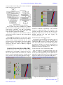
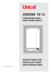
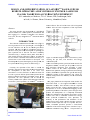
WEPD23
Proceedings of PCaPAC2012, Kolkata, India
DESIGN AND
D IMPLEM
MENTAT
TION OF LABVIE
EWTM BA
ASED GUII FOR
REM
MOTE OP
PERATIO
ON AND C
CONTRO
OL OF EX
XCIMER
R LASER FOR
PLASM
MA WAKE
EFIELD A
ACCELE
ERATION
N EXPER
RIMENT
K.K. Mohandas,
M
K.
K Mahavar, #R.A.V. Ku
umar, IPR, Gandhinagaar, India
S Joshi, A. Sharma, Niirma Univerrsity, Ahmeedabad, Indiia
S.
contrrol software. The GUI of tthe laser will be integratedd
with
h the GUI’s of
o other compponents of th
he experimentt
Abstract
The paperr describes the developmen
nt of a GUI bbased
control softw
ware for conttrol/operation,, maintenancee and
data loggingg of a Coherrent Compex
xPro 102 Exccimer
Laser (ArF, 1193 nm) usingg LabViewTM instrument coontrol
software.
INTRO
ODUCTION
N
mer laser (Figg.1) is
The Coherrent COMPexxPro102 Excim
an ArF gas bbased UV laser operating at
a a wavelenggth of
193 nm. Thiis laser uses Ar,
A F2, Ne, an
nd He gases ffor its
operation. Thhe laser can deliver
d
a max
ximum energyy of ~
200 mJ at 155 ns pulse widdth and capablle of operatingg at a
pulse repetittion rate of 1-20
1
Hz. The laser is norm
mally
controlled uusing a tetherred control panel
p
which hhas a
cable length restriction off around 3 meeters. In orderr that
the laser cann be controlled and monito
ored remotely,, it is
essential thaat a GUI baseed interface be developed. The
block-diagram
m of system showing
s
the gas feed system
m, the
I/O system annd the energyy meters is sho
own in Fig.2.
c 2012 by the respective authors
Copyright ○
Currently, the operatioon of the lasser is carriedd out
manually usiing the wired keypad. The main
m motivatiion of
the developpment of thhis GUI is for easier user
convenience as well as foor future use when
w
the laserr will
be used to ggenerate lithium photo-ionizzed plasma foor the
plasma wakeefield accelerrator experimeent system. In the
experiment, the laser operation
o
willl be carriedd out
remotely andd the laser sysstem will be integrated
i
witth the
accelerator ssystem operatiions via LabV
ViewTM instruument
Figgure 1: The Excimer laser system.
s
Figu
ure 2: Schemaatic diagram oof the excimerr laser system
m
showing the gaas lines, I/O
O interfaces and energyy
caliibration layoutt.
such
h as accelerato
or operation, pprecision heateer controls forr
the plasma
p
chamb
ber, vacuum //gas fill system
ms as well ass
data acquisition equipment, thus providiing a singlee
wind
dow control of the whoole experimeental system..
Routtine laser operration (settingg of parameterrs and runningg
of laaser), mainten
nance operatioons like gas fiill and energyy
calib
bration, loggin
ng of laser pparameters etcc., which aree
curreently being carried out maanually will be
b automatedd
using
g the GUI.
Th
his paper pressents the deveelopment of th
he module forr
the excimer
e
laserr, i.e., the reqquired LabVIE
EWTM virtuall
instrrument modu
ules, GUI intterfaces and the requiredd
displlay screens fo
or laser contrrol, parameterr display, gass
fill operation
o
as well as docuumentation/lo
ogging of thee
operrational param
meters of the laaser system. The
T paper alsoo
preseents the dev
velopment off a completelly automatedd
mod
dule for calibraation of the innternal energy
y meter of thee
excim
mer laser wiith a calibrat
ated external laser energyy
meteer (Coherentt FieldMax--II). This procedure
p
iss
neceessary as thee performancce and calibrration of thee
interrnal energy meter which is uused by the laaser system too
stabiilize its laser output
o
can var
ary over a periiod. This one-switcch, automateed operation provides a linear-fittedd
calib
bration of the internal energgy meter with that of a pre-meter. Thiss procedure iss
calib
brated commeercial energy m
----------------------------------------------ISBN
978-3-95450-124-3
#
[email protected]
Latest Trends in GUI
Proceedings of PCaPAC2012, Kolkata, India
WEPD23
usually carrieed out after eaach gas fill to make sure thaat the
health of the laser system is good.
Figurre 3: Flow-chart for Gas-Fill Operation.
Field-MAX
X-II-P energyy meter with an energy s ensor
optimized annd calibrated for
f use with 193 nm UV laaser is
used for extternal energy measuremen
nt. The UV s ensor
incorporates a DUV quarttz diffuser forr increased cooating
damage resiistance. The energy metter has USB
B I/O
connectivity and hence could
c
be seam
mlessly integgrated
into the laserr GUI.
MODULE FOR GAS-FILL
G
OPERATI
O
ION
Excimer Laser uses a mixture of various gases
depending oon the waveleength of operration of the laser.
The 193 nm operation of the laser usess he, Ne, Ar aand F
gases in varrious proportiions which are decided byy the
laser system at the time off gas filling op
peration. The ggas
Figure 5: Fron
nt-Panel for N
New fill and Pu
urge line.
riodically so as
a to maintainn
fills have to be caarried out peri
l
at its op
perating energgy. The flow
w-chart of thee
the laser
gas-ffilling processs based on w
which the GUI
G
has beenn
desig
gned is show
wn in Fig.3. IIn this GUI, gas flushing,,
new--fill, purge-gas line aand data logging aree
autom
matically carrried out.
Front Panel forr Flushing ggas Lines
Gaas flushing is an essential st
step to clear th
he gas lines off
all impurities
i
beefore the acttual gas fill operation iss
initiaated. When th
his operation iis initiated fro
om the “Flushh
Linee” GUI, all thee gas lines wiill be flushed using helium
m
gas and since Fluorine is a ccorrosive gass, that line iss
flush
hed twice as a precautionaary measure. The
T image off
the GUI
G for Flush Line is shown
wn in Fig.4.
Front Panel forr New-Fill aand Purge Line
L
Th
his GUI assissts in the gass-fill procedu
ure. Once thee
“NEW
WFILL” operattion is initiatedd, the GUI wiill prompt thee
user to open or clo
ose appropriatte gas valves (MV1/SV1
(
to
4/SV4) and go
o through the process of firrst evacuatingg
MV4
the gas
g lines and the laser cavityy and then fillling all the
Figure 6: Fron
nt-Panel for ppost gas fill paarameters.
Figurre 4: Front-Pannel for Flushinng gas lines.
ISBN 978-3-95450-124-3
Latest Trends in GUI
47
c 2012 by the respective authors
Copyright ○
The I/O coontrol of the laaser is establisshed via a stanndard
RS-232 interrface coupled to the PC through a RS-2332-toUSB interfaace. LabVIEW
WTM tools lik
ke web-publiishing
Tool, structuure palette, string, VISA palette have been
used to desiggn this graphiccal user interfaace.
The laser is designed to
t be controlled either from
m the
control paneel or from a remote
r
PC bu
ut not from booth at
the same tim
me.
WEPD23
Proceedings of PCaPAC2012, Kolkata, India
MODULE
M
FOR
F
LASER
R MONITOR AND
SE
ET PARAM
METERS
Th
his GUI is baasically to dissplay the vario
ous operatingg
and set parameterrs of the laserr. Parameters such as laserr
energy, laser rep
petition rate and mode of operationn
(Con
nstant energy or constant vvoltage) can be set. Also,,
theree is an option to activate thhe burst-modee operation off
the laser
l
if desired
d so by the usser. Flowchartt for this GUII
is sh
hown in Fig.7. Front-panel ffor this is show
wn in Fig.8.
Th
here are fourr basic operat
ating modes under
u
“Selectt
Mod
de” viz, HV-P
PGR, HV-NG
GR (constant voltage
v
modee
with
h and withou
ut gas purge)), EGY-PGR,, EGY-NGR,,
(con
nstant energy mode with an
and without gas
g purge) forr
settin
ng the running
g mode for thhe excimer lasser. At a time,,
only
y one of the fo
our options caan be activateed and can bee
chan
nged only afterr laser is in offf mode.
Figure 7: Flow chart for monitorr and set laaser
parameter.
required gasses at approppriate pressurres into the laser
system. Cuurrently, thesse gas valves are mannually
operated. In future, the whole
w
operatiion could be fully
automated if the manuual valves are replacedd by
electrically ccontrolled valvves. Once the gas fill is oveer, the
GUI will auttomatically flush the gas liines and purgge the
lines with innert gas for safety. The GU
UI for the gas fill is
shown in Figg.5. Post gaas-fill parameeters of the syystem
are shown vvia GUI show
wn in Fig. 6. This also loggs the
data to the loog file.
Front Paneel for Displaay of Laser Maintenannce
Parameterrs
Other sysstem maintennance parameeters such ass gas
pressures, fillter ratio (lifettime of the haalogen filter),, total
laser pulses, pulses after refill, tube teemperature etcc can
be displayed.
MODUL
LE FOR LA
ASER ENE
ERGY
CALIBRA
ATION
Th
he internal en
nergy meter oof the excimer laser taps a
smalll percentage of the laser bbeam to moniitor the beam
m
energy. This is ussed for stabilizzing the laserr output. Overr
time, the calibration of thiis internal energy
e
meterr
deterriorates and needs to be corrected ov
ver time. Thee
calib
bration of thee internal ennergy meter can be donee
again
nst a pre-calib
brated externaal energy meteer. By plottingg
the outputs
o
of both
h the internal aand external en
nergy meters att
vario
ous operating vo
oltages, one caan determine if the internall
energy meter is correct. If the calibration iss found to offf
by more
m
than an acceptable peercentage, then the internall
energy meter need
ds be physicaally recalibrateed. The flow-y calibration is shown in
n Fig.9. Thee
chartt for energy
“STA
ART CALIBE
ERATION” pprocess requirees the outputss
of bo
oth the laser and
a the externnal energy metter to be read,,
the data
d averaged and standard deviation deteermined for
c 2012 by the respective authors
Copyright ○
By using tthe “STARTR
RP” command
d, these param
meters
can be loggeed into an Excel file for laser maintennance
purposes. Thhe flow chart for
f this GUI iss shown in Figg.6.
Figure 8 : Frront-panel of Monitor
M
and laaser Set param
meter.
Figure 9: Flow-chart foor Energy Caliibration.
ISBN 978-3-95450-124-3
48
Latest Trends in GUI
Proceedings of PCaPAC2012, Kolkata, India
WEPD23
Rea
ad Command
d
Alll parameters (like operatioon-mode, mod
de, repetition-rate,HV, Energy, Pressure, Syystem time an
nd date, tubee
perature, etc.)) of excimer laser are read by runningg
temp
this VI.
V
LOGIC
CAL SUB--ROUTINE
ES
Figure 100: Front-Panell of Energy-C
Calibration GU
UI.
various voltaage levels. Thhe averaged daata is plotted in the
graph in-situu. After the prrocess ends, the
t data is savved in
Excel form, and finally pllotted against laser high vooltage,
as shown in F
Fig 10. The data
d points aree then linearlyy fitted
to obtain slopes, which arre then compaared to determ
mine if
the calibratiion of the innternal energy
y meter is w
within
acceptable liimits. The inteernal statisticaal math moduules of
M
LabVIEWTM
are used forr this. The log
gged data in Excel
format is shoown in Fig.11..
Th
here are five sub-routines under this VII. Password
sub VI
V is used forr the security purpose. Call VI is used
for to
t call VI from folder w
where it has been
b
saved.
Regrression is used to find relation beetween two
param
meters by lineear fit.
Matthematics
Th
hese sub-VIs are used forr to estimate mean, min,
max, standard dev
viation and sloope for data in
n the energy
bration operatiion.
calib
Save file
All data
d logging operations
o
are carried out by
y this VI.
Mullti Y-axes Graph
G
All multi
m
X-Y graaphical repressentations are carried out
by th
his VI.
Step
ps for Gas-ffill
Alll
user messages
m
rrelated
to
step-wise
explanation/confirrmation of thee manual partt of the gaso
are displayed to the user when this VI is
fill operation
run.
LABVIE
EWTM DRIV
VERS FOR
R EXCIME
ER
L
LASER
In this Virrtual Instrumeent driver (VII) file, all the SubVI drivers foor different coommands relaated to the exccimer
laser operatiion have beeen developed and incorporrated.
The VI-Treee showing thhe various VI’s
V
generatedd for
compiling thhis GUI depictted schematicaally in Fig.13..
Flush Com
mmand
There are four “Flush” commands are used to flussh gas
lines of thee various gasses used for operation o f the
excimer laserr (Halogen, Buffer,
B
Rare, an
nd Inert gasess).
Write Com
mmand
The four sub-routines under this VI
V are set/coontrol
functions rellated to runninng of the laser ie., “Run Laaser”,
“Stop Laser””, “Change vallue of HV”, “R
Repetition Raate” .
MODULE
M
S FOR EX
XCIMER LA
ASER
here are fo
our sub VII modules (like Port
Th
Initiaalization, Gaas-Fill operat
ation, Monito
or and set
param
meter and Energy calibraation) for ex
xcimer laser
whicch have been designed
d
undeer this modulee.
CONCLUSSIONS
GU
UI for port initialization,, setting and
d monitor alll
param
meters of excimer laser, gaas fill operatio
on and energyy
calib
bration for excimer
e
laserr are designed by seriall
interrface using RS-232, DB
B-9 connecto
or. But, alll
param
meters of exccimer laser aree monitor and
d set with onee
second or two second delayy. Virtual in
nstrument off
Exciimer laser and
d external enerrgy meter is designed usingg
LabV
VIEW™ softw
ware.
R
Real-Time Datta acquisitionn
will be done in vaarious file like
ke .doc,.pdf,.xlls,.txt etc. Alll
M
laserr operation will
w be done oon internet in LabVIEWTM
envirronment iff all com
mputers are connectedd
ISBN 978-3-95450-124-3
Latest Trends in GUI
49
c 2012 by the respective authors
Copyright ○
Figure 11: D
Data for energyy calibration saved in excel file.
WEPD23
Proceedings of PCaPAC2012, Kolkata, India
Figure 112: View of thhe plasma acceelerator laboraatory showing
g the ArF laser and the plasm
ma accelerato
or chamber.
in LAN.Autoomatic prograamming will be
b design for L
Laser
operations annd it will be change. Laserr operation w
will be
become fasteer and safe thaan it operate manually.
m
Laseer
ual for Coheerent FieldM
MaxII-P Laserr
[6] User Manu
Eneergy Meter.
[7] Béla G. Liipták, “Proceess Software and Digitall
Nettworking” In
nstrument Enngineer’s Haandbook, 3rdd
edittion, CRC preess, (2002).
[8] User Manual,, Coherent Ennergy Max Sen
nsors.
Figuree 13: The V-I tree
t for the Ex
xcimer laser.
operations aare easy to opperate and un
nderstand by user.
Laser Data w
will be transferred for long distance usingg RS232 to RS-4885 converter.
c 2012 by the respective authors
Copyright ○
ACKNOW
WLEDGME
ENTS
The authhors wish to thhank Mr. Yog
gesh Yeole andd Mr.
Jinto Thom
mas for vaarious help rendered with
M
LabVIEWTM
.
REFE
ERENCES
[1] John P
Park, Steve Mackay, and
d Edwin W
Wright,
“Practical D
Data Communnications for In
nstrumentationn and
Control,” Elsevier (2003)).
[2] Nationall Instruments LabVIEWTM 2010 –softwaare.
[3] Jovithaa Jerome, “Virtual Instrrumentation uusing
LabVIEW”, PHI Learninng Private Lim
mited (2010).
[4] Hexin RS-485 to RS-S232 in
nterface convverter
Model-485..
[5] Cohereent Interfacinng manual for COMPE
EXpro
(RoHS).
ISBN 978-3-95450-124-3
50
Latest Trends in GUI