1
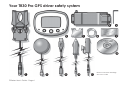
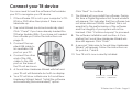
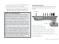
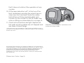
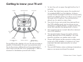
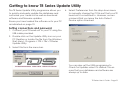
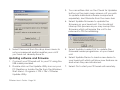
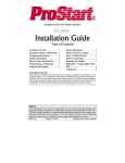
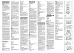
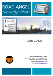
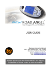
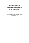
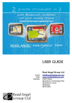
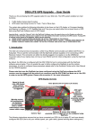
TECHNOLOGY DRIVEN SOLUTIONS
TR Series User Manual
TR Series User’s Guide - Page 1
For your safety
Notice
The Directors of Technology Driven Solutions Limited (TDS) supply the TR Series of GPS driver safety systems
as a road safety enhancement device. Driving within the designated speed limits at all times is a legal
requirement. We do not under any circumstances condone the use of inappropriate speed on a public
highway. You must drive within the limitation of the speed limit, the road conditions and your abilities. The
Directors of TDS take no responsibility for the use of a TR Series device for any other purpose than those
stipulated in this document.
Warning
Observe caution when selecting your source of power in the vehicle. DO NOT take power for this unit
from any safety or security device.
Make sure that all cables are carefully routed and do not interfere with any moving parts or air bags.
IF YOU HAVE ANY DOUBTS ABOUT INSTALLING THIS PRODUCT PLEASE CONSULT YOUR LOCAL ELECTRICIAN.
Suitability
The TR Series of GPS diver safety systems are NOT WATERPROOF and are NOT SUITABLE for motorcycles,
scooters, trikes or vehicles that are not protected from moisture.
Copyright © 2005-2006 Technology Driven Solutions Limited. All Rights Reserved.
Technology Driven Solutions Limited (TDS) shall not be liable for any errors contained herein or for any incidental loss, consequential loss or damages arising from either the use, misuse, correct or incorrect installation or mounting of TR20/30, TR30 Pro, TR20/30
Lite arising out of or related to this document or the information contained herein, even if TDS has been advised of the possibility
of such damages. This document is intended for informational and instructional purposes only. TDS reserves the right to make
changes in the specifications and other information contained in this document without prior notification. TDS disclaims any
obligation to update the information contained herein.
TDS, Technology Driven Solutions and TR20, TR30, TR30Pro TR20 Lite, TR30 Lite and Quantum db are registered trademarks of
Technology Driven Solutions Limited. Microsoft, Windows 98, Windows 98SE, Windows 2000, Windows NT and Windows XP and the
Windows Logo are trademarks or registered trademarks of Microsoft Corporation in the United Kingdom and/or other countries.
Second edition, January 2006.
TR Series User’s Guide - Page 2
Table of Contents
Introduction ................................................................................................................................................... 4
So what does it do? ..................................................................................................................................... 5
Your TR30 Pro GPS driver safety system ..................................................................................................... 6
Your TR20/30 Lite GPS driver safety system............................................................................................... 8
Register your device .................................................................................................................................... 9
Installing the software ................................................................................................................................ 10
Connect your TR device ........................................................................................................................... 11
Update your TR device .............................................................................................................................. 12
Installing your TR30 Pro ............................................................................................................................... 13
Installing your TR20/TR30 Lite ..................................................................................................................... 19
Getting to know your TR unit ..................................................................................................................... 21
User setup ..................................................................................................................................................... 23
Getting to know your TR Series Update Utility ........................................................................................ 31
Adding road hazards and speed enforcement zones ........................................................................ 38
Deleting road hazards and speed enforcement zones ...................................................................... 39
Troubleshooting .......................................................................................................................................... 40
Glossary ........................................................................................................................................................ 42
Speed enforcement .................................................................................................................................. 44
Global Positioning System (GPS) .............................................................................................................. 45
Customer Care Information ...................................................................................................................... 46
Two Year Limited Warranty ....................................................................................................................... 47
Index ............................................................................................................................................................. 48
TR Series User’s Guide - Page 3
Introduction
Thank you for purchasing your TR Series GPS driver
safety system.
the TR30/TR30 Lite this will be accompanied by a
change in colour of the display.
As congestion and regulation on our roads increases, staying alert to road and traffic conditions
is a challenge to all road users. Even the most
conscientious motorist can have a momentary
lapse of concentration that could easily lead to a
collision or a fine and points on their license.
If you approach a designated site and are travelling in excess of the speed limit you will hear a loud
beep and the red LED will flash. With the TR30 Pro/
TR30 Lite this will be accompanied by a change in
the colour of the display.
The TR Series of products is specially designed to be
a simple-to-use addition to most road going
vehicle and to alert you in advance of known road
hazard and speed enforcement zones. In the
comprehensive TDS database are stored police,
local authority and Department of Transport
designated road hazards, including accident
blackspots, speed enforcement zones and safety
camera locations.
Using the latest Global Positioning Satellite (GPS)
technology, the TR device compares your position
with the known road hazard and speed enforcement zones and gives you an audible and visual
warning as you approach them.
When approaching a designated site and you are
travelling within the speed limit you will hear a soft
beep at half the volume of a normal beep. With
TR Series User’s Guide - Page 4
Once you have corrected your speed, the unit will
return to a soft beep until the hazard has passed.
If you have a laser detector fitted your TR unit will
emit an audible tone to warn you of the presence
of laser targeting.
An accurate GPS speedometer in the display gives
you time to adjust your speed to the approaching
hazard. The safety of you the driver, your passengers
and other road users are our prime considerations.
We have confidence that for all of the time spent
in your vehicle, the TR Series of products will enhance the safety and enjoyment of your journey.
Join other TR Series users in safeguarding your life
and livelihood. We are pleased to have you as a
valued customer and hope you will be delighted
with your purchase.
Drive Safe.
Drive Smart with Technology Driven Solutions.
So, What Does It Do?
QUITE SIMPLY, it helps you become a safer driver by
forwarning you about road hazards such as
accident blackspots and alerting you to speed
enforcement zones.
In fact, your TR device should keep you and other
road users, safe from those momentary lapses of
concentration that could end in injury, a fine or
indeed an endorsed license.
Your TR device is 100% legal and many police
forces recognise that these products make a
valuable contribution to road safety.
Your TR device has been designed to give you the
most up to date information, for your convenience
and ease of use.
There is a glossary at the end of the manual (see
page 40) to explain each of the different types of
speed camera, but in essence, all current devices
are logged on your TR unit, including Gatso,
Truvelo, SPECS, Watchman, Speedcurb, DS2, Safety
Camera Vans and Mobile Laser.
A range of features set it apart from other devices,
including:
Your TR unit identifies specific Blackspot locations
where a high number of road related accidents
have occured, such as difficult junctions.
With the growth of congestion charging in cities
around the UK expected and the increase in toll
roads, your TR warns you of their operation.
Your TR unit also keeps a log of schools around the
country to give you greater awareness of children
at the roadside, who are unpredictable and less
road aware than other users.
You can even add up to fifty of your personal
‘hazard’ locations.
• clear, high quality LCD, designed to be visible in
bright sunlight,
• multi-colour backlight, fully adjustable
backlight to match your vehicle’s dashboard
illumination (TR30 Pro/TR30 Lite only),
• audible warning, clear sounding audible alerts
allows you to concentrate on the road ahead
• mute wire, the TR30 Pro unit can be permanently
installed and can mute the radio if your vehicle’s
audio system can support this function
• USB connection, easy connection to your PC
using USB cable
• PC compatible configuration, all menu options
are adjustable via the PC to give you easy and
effective personalisation.
TR Series User’s Guide - Page 5
Your TR30 Pro GPS driver safety system
5
2
7
8
6
9
12
1
TR Series User’s Guide - Page 6
3
4
10
11
Please note these drawings
are not to scale
TR30 Pro GPS driver safety system
Designed for full in-car installation and flexibility the TR30 Pro system
offer a comprehensive installation kit.
1. In-car mounting cradle
2. TR30 Pro Head unit
3. GPS antenna
4. USB cable
5. Interconnect control module
6. Hex allen key 2.5mm A/F
7. Self adhesive gel pad for cradle mounting
8. Gel pad for antenna
9. Solvent based cleaning wipe
10. Cigar lighter power cable, 12 volt, fused at 1 amp (fuse size 20mm)
11. Laser detector c/w mounting bracket and suction cup for windscreen mounting. (optional extra for TR20 Lite)
12. Software CD containing User Manual & product management
software
13. Quick Start Guide (not shown)
TR Series User’s Guide - Page 7
Your TR20/30 Lite GPS driver safety system
TR20/TR30 Lite system
Designed for ease and flexibility
the ‘Lite’ system ensures you will
will be ready for the road almost
instantly!
1. In-car mounting cradle with
windscreen suction
2. TR20/TR30 Lite Head unit with
integrated GPS antenna
1
2
3. USB cable
4. Cigar lighter power cable
(12 volt fused at 1 amp)
Side view of TR20/30
Lite head unit showing
integrated GPS
antenna
5. Laser detector
(optional extra for TR20 Lite)
6. Software CD
7. Quick Start Guide (not
shown)
3
4
TR Series User’s Guide - Page 8
5
6
Please note these drawings are not to scale
Register your device
If you have not already done so you should register
your device immediately BEFORE you connect your
TR unit. This will ensure you receive the latest road
information and to start your FREE six months
subscription*.
1. Locate the serial number on your TR unit. The
serial number is on the back of your TR30 Pro
unit as shown and underneath the GPS
antenna of the TR20/30 Lite.
2. Connect to the internet and visit
http://www.tds-tr.com.
3. Click on the register button and complete the
registration form using a memorable password.
Please note that the password is case sensitive.
* Subscriptions are available after the expiry of the initial FREE six months.
Please visit www.tds-tr.com or contact your local dealer for current
subscription rates and terms.
TR Series User’s Guide - Page 9
Installing the Software
You are now ready to install the USB drivers and
the TR Series Update Utility which manages your
personal settings and the road information on your
unit. The supplied CD-ROM is suitable for all PCs
running Microsoft Windows. See system requirements below.
4. Click the Yes button.
5. During the installl process a shortcut icon will be
created on your desktop.
1. Insert the software CD label side up into your
computer’s CD-ROM or DVD drive.
2. The Install Wizard should automatically start.
If for any reason the install programme does
not start, click on the Start button in the bottom
left hand corner of the screen and select Run...
Click the Browse button and locate the CD on
your CD-ROM or DVD drive. Select the
TRxSetup.exe file and click on the Open button.
PC system requirements
Click the OK button which will launch the Install
Wizard.
•
•
3. Follow the on screen instructions for the
installation. During the install process a Digital
Signature Not Found window will appear. This
indicates that the software has not been
Microsoft WHQL certified. This is not essential to
the performance of the software and the
integrity of your system will not be harmed.
TR Series User’s Guide - Page 10
•
•
•
Microsoft Windows 98SE, 2000, Me or XP
233MHz Pentium II processor or higher with
64MB RAM
USB port
CD-ROM drive
Internet connection recommended.
Connect your TR device
You now need to load the software that enables
your PC to recognise your TR device.
1. If the software CD is not in your computer’s CDROM or DVD drive then place it there now
label side up.
2. The Install Wizard should automatically start.
Click “Canel” if you have already loaded the
TR Series Update Utility. If you have not loaded
the software yet, follow the instructions on
page 10.
3. Connect the supplied USB cable to
an available USB
port on your PC.
4. Connect the other
end of the USB
cable to the USB
port on the base of
the TR unit as shown.
Click “Next” to continue
7. The Wizard will now install the software. During
this time a Digital Signature Not Found window
will appear. This indicates that the software has
not been Microsoft WHQL certified. This is not
essential to the performance of the software
and the integrity of your system will not be
harmed. Click “Continue Anyway” to proceed.
8. The software installation will contine. A Completing the Found New Hardware Wizard window will appear. Click “Finish”.
9. A second “Welcome to Found New Hardware
Wizard” will appear. Follow the instructions as
for points 6, 7 and 8.
10. Your TR unit is now correctly installed.
5. A Found New Hardware Wizard will start and
your TR unit will illuminate but with no display.
6. Your PC will show a Welcome to Found New
Hardware Wizard. Select “Install the software
automatically (Recommended)” option.
Connect to Connect USB
cradle here cable here
TR Series User’s Guide - Page 11
Update your TR device
TDS are constantly updating their Quantum database with new information about the latest road
hazards, speed enforcement zones, toll roads and
a host of other features. We recommend that you
update your unit immediately and on a regular
basis (weekly) thereafter.
1. Double click on the TR Series Update Utility icon
situated on your desktop.
2. Open the File menu and select Password.
3. Enter the password exactly as you entered it on
the registration page. Remember that the
password is case sensitive. Click OK.
4. If you are not already connected to the
Internet, please do so now.
5. Click on the button Check for Updates. The
software will now update the data on your TR
device. When the operation is complete a
message will show Update Successful. Click OK
to continue.
TR Series User’s Guide - Page 12
Installing your TR30 Pro
TDS recommend that your TR unit is professionally
installed. You can contact us at http://www.tdstr.com for a list of recommended installers. If you
do decide to install this product yourself we draw
your attention to the notes at the end of this
section. (see page 20)
If you install the unit yourself we recommend a ‘soft
install’ to confirm the best position for the head unit,
GPS antenna and interconnect control module.
1. Unpack and check the contents of the box.
2. Connect the antenna to the interconnect
contol module. Ensure the connection is
screwed tightly in place.
3. Connect the cigar lighter power lead to the
control module.
4. Position the cradle on the dashboard but do
not fix it at this stage. You may find a piece of
Blu-tak helpful.
5. Plug in the cigar lighter power lead and turn on
the ignition key to power the unit up.
6. Your TR unit will now illuminate and search for
satellites. Ensure your antenna has a clear view
and is not hampered by external objects such
as buildings or windscreen wipers. Satellite lock
normally takes between 20 seconds and 2
minutes. Ordinarily the driver’s side (off-side) of
the dashboard will receive less interferance
from buildings and overhanging trees etc.
7. If you are experiencing problems with satellite
lock, move the antenna around the dashboard
or in some cases you may find the rear parcel
shelf is a better location.
Metallised windscreens
Certain vehicles, such as some models of
Mercedes, Renault, Peugeot and Citroën have
a metallised UV filter layer within the windscreen
that may block GPS signals, which will prevent
your TR device acquiring its position.
If you have problems with satellite lock, try
locating the GPS antenna on the rear parcel
shelf or on one of the side panels of the load
space if fitting to an estate car.
Heated front screens, such as those found in
some Ford vehicles may also affect signal
strength. In this instance there are gaps to the
left and right of the heater elements which may
be large enough to receive GPS signals.
TR Series User’s Guide - Page 13
Once you have established the best position for
the antenna, you are ready to fully install your TR
GPS driver safety system.
8. Disconnect all cables.
9. Decide on which mounting option you prefer:
- double-sided sticky gel pad
- custom manufactured bracket (e.g. Dash
Mount; visit http://www.dashmount.co.uk)
- screwing directly to a suitable surface
10. If you select the double-sided sticky gel pad
option, locate the solvent wipe and open the
pack carefully so that it can be used to retain
the wipe for multiple uses.
11. Clean the rear flat side of the in car mounting
cradle. Place the solvent wipe back in its pack
for use later. Wait for the solvent to dry.
12. Peel off one side of the double-sided sticky gel
pad and affix to the area that you have just
cleaned on the mounting cradle. DO NOT PEEL
THE OTHER SIDE OF THE PAD YET.
13. Place the components to be installed approximately in their final locations, e.g. antenna on
the dashboard, head unit in line of sight and
within easy reach, the interconnect module
TR Series User’s Guide - Page 14
somewhere in the footwell (this will be mounted
in a concealed position later). Ensure that
cables can be routed in a safe and tidy way
and will not interfere with the operation of the
vehicle in any way.
14. Connect all the items together referring to the
connection guide below.
15. Finalise the position of the TR head unit by
sitting in the driver’s seat and positioning the
head unit fitted to the mounting cradle to
ensure a good view of the screen without
compromising access to any of the vehicle’s
controls; also ensuring there is a safe and tidy
route for the cable to pass from the cradle
down to the interconnection unit.
16. The mounting cradle comes with 2.5mm cap
head recessed bolts which can be tightened
to ‘finger tightness’ which will allow some
movement after installation.
17. Once you have chosen your final mounting
position, remove the head unit from the
bracket and use the solvent cleaning pad to
clean the proposed location for the cradle on
the dashboard. Once dry, remove the protective layer from the gel pad and press down on
the base firmly. DO NOT APPLY PRESSURE ON
THE HEAD UNIT PART OF THE CRADLE.
18. Mount the GPS antenna in the location determined from your ‘soft install’ (see page 13).
Wipe both surfaces using the solvent wipe
Connection Guide
Please Note: Ensure all cables are safely routed
and do not interfer with the operation of your
vehicle.
Connect
antenna here
1
2
3
4
5 6 7 8 910
Siting your laser detector
Tests on laser speed enforcement equipment,
carried out by our engineers, have found the
most effective position for a single detector is
on the front windscreen, half way up with clear
views out of the front and rear windows.
There will be a compromise between the optimum position and the most practical, as there
will be obstructions such as windscreen wipers,
front seats, headrests, items on the parcel shelf
etc.
At over 200m the laser detection unit has been
shown to warn every time a vehicle (standard
saloon car) was targeted. If the laser speed
enforcement equipment targets your front or
rear number plate at less than 200m it is likely
that a dahsboard mounted laser detection unit
WILL NOT detect the signal. At 200m the beam
of a laser can be as narrow as 200mm.
Connect
cradle here
1. Socket1: Laser dector input.
2. Socket 2: Accessory input TR30 only.
3. Socket 3: Accessort input TR30 only.
4. Cigar lighter input: 12 volts (See important notice on page 16).
5. Vehicle Ground (marked G): connect to vehicle bodywork.
6. Switched live (marked SW): connect to vehicle accessory wire.
7. Permanent live (marked PL): connect to permanently live wire.
8. Radio mute (marked M): connects to audio system phone mute input.
9. Low level audio input -ve.
10. Low level audio input +ve.
TR Series User’s Guide - Page 15
before attaching the self-adhesive gel pad to
the antenna first and then the dashboard.
19. With care, route the antenna cable towards
the position that you have selected to mount
your interconnect module - behind, under or
between any panels that give a safe and tidy
appearance to the installation .
Please note: Do not crimp or crush this coaxial
cable as it is not possible to reliably join this
type of cable without the use of specialist
connectors such as the one fitted.
20. If you have a laser detector (standard with TR30
Pro/TR30 Lite and an optional extra for all other
models), select a suitable position to mount the
combined front and rear detection head that
will allow you to route the cable back to the
interconnect module safely and tidily.
21. Remove the under dash cover panel and
select a suitable position in which to securely
mount the interconnect module. When using
cable ties to mount the interconnect module
you may use a wiring loom or perhaps an air
pipe as long as this does not impede the
operation of any of the vehicle’s systems.
TR Series User’s Guide - Page 16
If you decide to screw the interconnect module
under the dashboard you MUST exercise extreme
caution on the selection of the mounting site so
that damage is not caused to your vehicle’s
wiring looms, air conditioning or heating etc.
Do not finish mounting the interconnect module,
there are still cables to connect.
22. Now you have a final location for the interconnect module you may connect all the
routed cables to their correct sockets.
Important Notice
The TR unit, interconnect module or any of the
associated components or wiring should not be
attached to any moving part of the ventillation
system, steering mechanism or any other part
that may move in the operation of the vehicle or
placed across the surface of any of the airbags
(SRS) installed in the vehicle.
All wiring must be suitably installed to ensure it
does not interfere with the operation of the
airbags or any of the vehicle’s controls.
Failure to observe this cautionary note may lead
to injury should an airbag fail to deploy in the
event of a road traffic accident or a malfunction
of the SRS.
Connecting power to your TR device
You can either connect your TR unit to the cigar
lighter socket or you can hardwire the unit to the
vehicle’s power supply.
The benefit of hardwiring your TR device is that you
will have ‘instant’ satellite lock when returning to
your vehicle.
23. Cigar lighter power lead option
Plug the cigar lighter lead into the cigar lighter
socket and select a suitable route for the cable
to the interconnect module ensuring that it is
safe and tidy and does not interfere with the
operation of the vehicle. Attach the head unit
to the cradle and check that the system is
working correctly before securing the under
dash cover panel and any other panels that
you have removed in the process of installing
your device.
24. Hardwiring option
Please note: Please read the following carefully
before installing. If in any doubt consult your
dealer or a qualified auto electrician.
Do not under any circumstances take power from
any safety or security device fitted in your vehicle.
Select a wire that will remain permanently live
when the vehicle’s iginition is switched off.
Make a note of it. This is your permanent live
feed.
Select a wire that will become live when the
vehicle’s iginition is either in the accessory
position or when the iginition is fully on. Make a
note of it. This is your switched live feed.
Select a wire that will give you a suitable
ground connection or a ground connection
cluster on the vehicle’s bodywork. Make a note
of it. This is your vehicle ground.
Should you wish to take advantage of the
radio mute option you may find this wire on the
back panel of your vehicle’s audio system. We
advise you to consult with your dealer or a car
audio specialist to ascertain whether your
audio system supports this function and its
compatibility. Once you have all the necessary
wires to make the connections, follow the
connections guide on page 15.
When you have made all the connections,
connect the head unit*, checking that it is
working correctly before securing all items and
refitting any panels removed during installation.
TR Series User’s Guide - Page 17
*Please note: We recommend that connections be made by removing say 10mm of
insulation, wrapping the bared end of wire
around the wire you wish to connect to and
then soldering and applying heatshrink tubing
to the final connections to give adequate
insulation. If an any doubt consult your dealer
or a qualified auto electrician.
TIP: You may find all the wires you require are
on the back of the vehicle’s audio system.
25. Your device should now be safely and securely
installed in your vehicle.
TR Series User’s Guide - Page 18
Installing your TR20/TR30 Lite
The TR Lite range of products are plug and play
devices designed for ease of installation and
flexibility and do not require ‘hardwiring’ to your
vehicle.
They can be used with all 12 volt motor vehicles
and are connected to the vehicle’s electrical
system via the cigar lighter socket.
The GPS antenna is integrated into the head unit
which means an external antenna is generally not
necessary. (See Metalliised windscreens on page 13)
TDS recommend a ‘soft install’ to confirm the best
position for your mounting cradle and head unit.
1. Unpack and check the contents of the box.
2. Find a suitable area of the windscreen to
attach the sucker mounting cradle. Ensure that
it does not impede your driving vision.
3. Attach the cradle to the windscreen by placing the sucker on the windscreen and depressing the lever.
4. Connect the TR head unit to the cradle ensuring that the antenna on the back of the unit is
horizontal, that it has a clear view vertically
and is not hampered by internal or external
objects such as metal tax disc holders, buildings
or windscreen wipers.
5. Connect the cigar lighter power lead to the
cradle. Please note that this lead has an internal fuse rated at 1 amp. If you need to replace
the fuse, make sure to use an identical sized
fuse with the correct rating.
6. Plug in the cigar lighter power lead and turn on
the ignition key to power the unit up.
7. Your TR unit will now illuminate and search for
satellites. Satellite lock normally takes between
20 seconds and 2 minutes.
8. If you are experiencing problems with satellite
lock, try another spot on the windscreen and
check that there are no external obstructions
such as tall buildings. Should you still have
difficulties it may be that your windscreen is of
a type that is metallised. In this instance you will
need to purchase a separate antenna which is
available from your supplying dealer or our
website at www.tds-tr.com.
9. Once you have established the best position
for the TR device you should route the cable
safely to the cigar lighter socket and ensure
TR Series User’s Guide - Page 19
that it does not obstruct the operation of any
controls.
10. Fit the laser detection unit* to the top of the
front windscreen ensuring the sensors have a
clear view front and rear. Route the cable
behind the roof lining and side pillars and
connect to the connect to the TR cradle. See
notes on Siting your laser detector on page 15.
11. Check all connections are tight. Replace all
trim parts ensuring cables are not trapped and
are clear of screw fixings.
* Laser detection unit is available as standard with the TR30 lite and as a
cost option for the TR20 Lite. Please consult your dealer or visit our website
at www.tds-tr.com.
Technology Driven Solutions Ltd. shall not be liable for any incidental loss,
consequential loss or damages arising from either the use, misuse, correct
or incorrect installation or mounting of the TR20/30 or TR20/30 Lite or any
of the directly associated components. By continuing to install this
product you are deemed to have accepted these terms and
condictions. If you are in any douby please consult your dealer and/or
auto electrician.
TR Series User’s Guide - Page 20
TR20/TR30 Lite mounted to windscreen with
sucker mounting cradle
Getting to know your TR unit
1. To turn the unit on press the right button for 2
seconds.
Clock
Speedometer
Compass
2. To enter the Main Menu press the centre button marked MENU on the display. In Menu
mode the left and right buttons act as Up (Left)
and Down (Right) buttons to allow you to scroll
through a list of options. The centre button
allows you to select a menu item.
3. The clock shows accurate time derived from
the GPS satellites and can be shown as an
analogue or digital display. In alert mode the
clock will indicate the speed limit in force.
Green
LED
Red
LED
Left
button
Centre
button
Right
button
(Add NEW sites,
Up)
(Menu, Select)
(Illumination
Night Dim, Down
The multifunction display of your TR unit provides a
wealth of information for your convenience and
the buttons have different functions dependant
upon which mode the unit is operating in. Take a
moment to familiarise yourself with these.
4. The compass shows current direction derived
from GPS satellites.
5. The speedometer shows accurate vehicle
speed derived from GPS satellites. You can
specific whether you prefer mph or kph.
6. Green LED flashes while receiver locates and
locks onto GPS satellites. A minimum of 3 are
required. Remains premanently on when
locked on.
7. The red LED flashes when entering a hazardous
area or an area monitored for speed.
TR Series User’s Guide - Page 21
Left button
8. The left button in standard display mode with
no warnings allows you to ADD a new location
such as a road hazard or speed enforcement
zone. You can add up to fifty personal locations. See page 38.
In warning mode the left button offers you an
opportunity to DELETE a location. Please note
that sites designated in the TR database will not
be deleted until verified by TDS. See page 39.
In Menu Mode the left button allows you to
scroll up and down a menu list to make a
selection with the centre button. Scroll works in
a loop, up and down, ie you can scroll through
the top of the menu list to get to the last item
on the menu and vice versa.
Right button
9. The Illumination night dim can be set using the
right button in standard display mode while the
unit is not displaying a warning.
The brightness of the illumination night dim can
be set in the TR Update Utility (see page 33).
Press the right button again to reset to your
original brightness level.
TR Series User’s Guide - Page 22
Please note that the unit will display in full
brightness during an alert and will reset when
power is removed from the unit.
In Menu Mode the right button allows you to
scroll up and down a menu list to make a
selection with the centre button. Scroll works in
a loop, up and down, ie you can scroll through
the top of the menu list to get to the last item
on the menu and vice versa.
Centre button
10. In standard display mode the centre button
accesses a number of Menus to set your unit’s
operating preferences.
In Menu Mode the centre button is used to
Select a menu item or toggle between a
number of options.
User setup
1. To turn the unit on press the right button for 2
seconds.
Main Menu
2. To enter the Main Menu
press the centre button
marked MENU on the
display. In Menu mode
the left and right buttons
act as Up (Left) and Down (Right) buttons to
allow you to scroll through a list of options. The
centre button allows you to select or change a
menu item.
Trip Stats Menu
3. Highlight the “Trip Stats” option and press the
centre button (Slct) to
view your journey details,
including trip time,
distance travelled and
average speed. You can
reset your Trip Stats by
selecting the Reset option.
To exit the Trip Menu highlight the Exit option
and press Slct.
Alert Menu
4. Highlight the “Alerts” option using the Up and
Dn buttons and press Slct.
Proximity
The Proximity option
allows you define
whether you want your TR
unit to give you
advanced notice of road
hazards or speed enforcement zones by a set
time or a set distance. You can toggle between Time or Distance by highlighting the
Proximity option using the Up and Dn buttons
and pressing Slct.
Distance
If you have set the Proximity setting to Distance
you can define how far,
in metres, from the road
hazard or speed enforcement zones you wish to be alerted by your TR
unit. This should be set to a distance that will
allow you, if necessary, to alter your driving
safely given the road conditions.
TR Series User’s Guide - Page 23
The distance to alert can be adjusted from 200
to 2,000 metres in 50m increments by using the
‘+’ and ‘-’ buttons and pressing Ok when ready.
Factory default value is 600 metres.
Time
If you have set the
Proximity setting to Time
you can define how far,
in seconds, from the road
hazard or speed enforcement zone you wish to be alerted by your TR
unit. This should be set to a time that will allow
you, if necessary, to alter your driving safely
given the road conditions.
The distance to alert can be adjusted from 5 to
60 seconds in 1 sec increments by using the ‘+’
and ‘-’ buttons and pressing Ok when ready.
veh icle sp eed
Factory default value is 15 seconds.
Please see the table below as an indicator for
your own personal settings. They are produced
for your guidance only and will vary with road
conditions.
Blackspot
You can set your TR unit to alert you of known
accident blackspots. Use the Up and Dn buttons to highlight the Blackspot option and press
Slct to toggle between YES or NO.
Congestion
You can set your TR unit to alert you of congestion charge areas. Many cities apart from
London are considering and/or adopting
congestion charge schemes. Use the Up and
Dn buttons to highlight the Congestion option
and press Slct to toggle between YES or NO.
d ista n ce tra velled in m etres
mp h
kph
30
48
67
134
201
402
604
805
40
64
89
179
268
536
805
1,073
50
80
112
224
335
670
1,006
1.341
70
110
156
313
469
939
1,408
1,878
TR Series User’s Guide - Page 24
5 secs
10 secs
15 secs
30 secs
40 secs
60 secs
Toll Road
You can set your TR unit to alert you of toll
roads/bridges/tunnels. Use the Up and Dn
buttons to highlight the Toll Road option and
press Slct to toggle between YES or NO.
Adjust the volume using the
‘+’ and ‘-’ buttons and
pressing Ok. The unit will
beep to give an indication
of the volume.
Schools
You can set your TR unit
to alert you of schools.
Use the Up and Dn buttons to highlight the
School option and press
Slct to toggle between YES or NO.
Remember to to take into account the ambient
noise in your vehicle when adjusting the volume.
Exit
Scroll up or down to highlight Exit and press Slct
to return to the Main Menu.
Adjust the volume using the ‘+’ and ‘-’ buttons
and pressing Ok. The unit will beep to give an
indication of the volume.
Factory default setting is 22.
Mute Vol.
If you have installed the mute audio option in
your vehicle you can set the volume of the alert.
Sound Menu
Factory default setting is 11.
5. From the Main Menu
highlight Sound using the
Up and Dn buttons and
pressing Slct.
Voice Vol.
All TR Series units have an option for a female or
male voice warning. This can be selected using
the TR Series Utility Update programme. (see
page 31)
Beep Vol.
Your TR unit has an audible ‘beep’ warning. To
adjust the Beep Volume between 0 and 31
highlight the Beep Vol. option using the Up and
Dn buttons and press Slct.
In addition the TR30 Pro/TR30 Lite offers a number
of character voices to personalise your device
further. These are available for you to download
from www.tds-tr.com.
TR Series User’s Guide - Page 25
Adjust the volume using the ‘+’ and ‘-’ buttons
and pressing Ok. The unit will play the voice to
test the volume.
Remember to to take into account the ambient noise in your vehicle when adjusting the
volume.
Factory default setting is 22.
Voice Alert
You can switch the Voice Alert on or off by
highlighting the Voice Alert option using the Up
and Dn buttons and toggling between YES or
NO.
The factory default is YES.
Exit
Scroll up or down to highlight Exit and press Slct
to return to the Main Menu.
Display Menu
6. From the Main Menu
highlight Display using the
Up and Dn buttons and
pressing Slct.
TR Series User’s Guide - Page 26
Brightness
You can increase or decrease the brightness of
your TR unit to suit your
interior lighting. To adjust,
select the Brightness option
using the Up and Dn buttons and press Slct and
then use the ‘+’ and ‘-’ buttons to increase or
decrease the display brightness.
Contrast
You can increase or decrease the contrast of your
display. From the Display
Menu select Contrast using
the Up and Dn buttons and
pressing Slct.
The Contrast screen will open. You can adjust
using the ‘+’ and ‘-’ buttons and saving the
setting by pressing Ok.
The factory default setting is 13.
Analog. Mode
You can opt to display the clock and compass
in analogue or digital mode. From the Display
Menu select Analog. Mode using the Up and
Dn buttons. Pressing Slct will toggle between
YES and NO.
Inverse
Your display can be reversed from black on
white to white on black using the Inverse
option. From the Display Menu select Inverse
using the Up and Dn buttons. Pressing Slct will
toggle between YES and NO.
Exit
Scroll up or down to highlight Exit and press Slct
to return to the Main Menu.
Misc Menu
7. From the Main Menu
highlight Misc using the
Up and Dn buttons and
pressing Slct.
Demo
To access a demonstration of your TR unit,
highlight the Demo option in the Misc Menu
using the Up and Dn buttons and pressing Slct
to toggle between YES and NO.
Select YES and select Exit using the Up and Dn
buttons. You should be at the Main Menu.
Select Exit from the Main Menu and the unit will
begin demonstration mode.
To exit the demonstration press Menu and
return to the Misc Menu. Highlight the Demo
option and toggle the option to NO using the
Slct button to disable demo mode.
Spd Warn
You can set an ‘overspeed’ warning which
notifies you each time you exceed a set speed.
Highlight the Spd Warn option using the Up and
Dn buttons and toggle between YES or NO if
you wish to enable or disable this feature.
Warn Spd
If you opted for the
Speed Warning option
above you can now set
the speed that you wish
to be alerted of exceeding.
Highlight the Warn Spd option using the Up and
Dn buttons and press Slct.
You will be taken to the Speed Warning screen.
Adjust to the desired speed using the ‘+’ and ‘-’
TR Series User’s Guide - Page 27
buttons and pressing Ok to save.
Speeds are adjusted in increments of 5mph
between 50mph to 100mph.
The default factory setting is 70mph.
A. Pwr. Off
Auto Power Off conserves vehicle battery
power when your vehicle has been left for a
long period of time. TDS always recommend
removing the head unit when leaving your
vehicle for extended periods.
To set Auto Power Off, highlight A. Pwr. Off using
the Up and Dn buttons and using the Slct
button to toggle between YES and NO.
Mute Option
If you have installed the
mute feature to your car
audio system you can
select the following
options:
0 - Off: mute feature not installed
1 - Mute on Voice: will mute audio on a voice
alert if you have voice alerts enabled
TR Series User’s Guide - Page 28
2 - Mute on Overspeed: will mute audio on
should you exceed your speed warning
(see page 27)
3 - Mute Whilst Alerting: will mute your audio
system for beep and voice alerts.
To set highlight Mute Option in the Misc Menu
using the Up and Dn buttons and Slct.
In the Mute Option screen, use the ‘+’ and ‘-’
buttons to adjust the desired Mute Option
between 0 and 3.
The factory default setting is 1.
Speed Units
To set Speed Units in miles per hour or kilometres
per hour use the Up and Dn buttons and press
Slct to toggle between MPH and KPH.
Subs
The Subs option allows
you to check the expiry
date of your current
subscription, how many
days are left till renewal
and gives access to the Serial Number of your
unit.
Highlight Subs in the Misc Menu using the Up
and Dn buttons and press Slct.
To return to the Misc Menu press EXIT in the
Subscription screen.
Position
The Position option shows
your current Bearing in
degrees and GPS location in Latitude and
Longitude in degrees,
minutes and seconds.
Highlight Position from the Misc Menu using the
Up and Dn buttons and press Select. This will
open the Location screen.
To return to the Misc Menu press EXIT.
Sat Lock
Sat Lock shows you how
many satellites are
locked on by your TR unit.
The minimum requirement
for your device to
operate effectively is three. See page 45 for
more information about GPS.
Highlight Sat Lock from the Misc Menu using the
Up and Dn buttons and press Select to access
the Satellite View screen.
To return to the Misc Menu press EXIT.
Version
Version comprises data
about your unit for troubleshooting.
Highlight Version from the
Misc Menu using the Up
and Dn buttons and press Slct to open the
Version window.
The software version relates to the latest
firmware upgrade on your device.
Locations refers to the date that you last updated your data. TDS recommend that your
data is updated regularly (weekly if possible).
Unit identifies the model of your TR unit.
Serial Number is the unique identifier for your
device.
To return to the Misc Menu press EXIT.
TR Series User’s Guide - Page 29
Exit
Scroll up or down to highlight Exit and press Slct
to return to the Main Menu.
8. Defaults
Should you wish to restore
all of the factory default
settings highlight the
Defaults option from the
Main Menu.
Press Slct to open the Defaults screen. If you
wish to continue with reseting the device press
the Confirm button on the left, otherwise press
Exit and you will be returned to the Main Menu.
9. Exit
Returns you to the display screen as shown on
page 21.
TR Series User’s Guide - Page 30
Getting to know TR Series Update Utility
The TR Series Update Utility programme allows you
to quickly and easily update the database and
customise your head unit as well as download
software and firmware updates.
Ensure you have loaded the software onto your PC
as indicated on page 10.
4. Select Preferences from the drop down menu
to manually change the COM port that your TR
head unit is connected to. However, we recommend that you leave the Auto Detect
Device option checked.
Setting connections and password
1. Connect your TR head unit to your PC using the
USB cable provided.
2. Double-click on the Update Utility icon on your
PC Desktop or locate the file from the Windows
Start Menu - Programs > TDS > TRx > TR Series
Update Utility.
3. Select File from the menu bar.
You can also set the Utility programme to
Check for Updates when it is started. This ensures that your database and software are
always up to date.
TR Series User’s Guide - Page 31
3. You can either click on the Check for Updates
button on the main menu screen or if you wish
to update individual software components
separately, slect Remote from the menu bar.
4. Select Update Firmware to update the
firmware on your head unit. You should not
interrupt this process as you may corrupt the
firmware which will require the unit to be
returned to TDS for reflashing.
5. Select Password from the drop down menu to
set your password and/or register your unit if
you have not already done so.
5. Select Update Loader F/W to update the
Firmware loader programme on your head
unit.
Updating software and firmware
6. Select Update Demo to load a new demo to
your head unit which will show new features as
and when they are introduced.
1. Connect your TR head unit to your PC using the
USB cable provided.
2. Double-click on the Update Utility icon on your
PC Desktop or locate the file from the Windows
Start Menu - Programs > TDS > TRx > TR Series
Update Utility.
TR Series User’s Guide - Page 32
7. Select Go to start your TR head unit remotely.
Customise your TR unit
1. Connect your TR head unit to your PC using the
USB cable provided.
2. Double-click on the Update Utility icon on your
PC Desktop or locate the file from the Windows
Start Menu - Programs > TDS > TRx > TR Series
Update Utility.
3. You can either click on the Change Settings
button or select Remote from the menu bar
and then chose Settings.
such as red, for your Alert Screen and a contrasting but distinctive colour to attract your
attention for the Soft Alert Screen such as
Green or Orange.
The Illumination night dim can be set by adjusting all the RGB slider controls to a percentage
of their full brightness. For example you may set
each of the RGB levels to approximately 20%
4. The Settings window will open and show four
tabs which will access Display, Alerts, Sound
and Misc settings pages.
Display Tab
Back Light
Adjusts the colour of your Normal, Alert and Soft
Alert for the TR30 Pro/TR30 Lite only.
Select Normal and using the Red, Green and
Blue slider controls adjust the colour to suit your
internal dashboard illumination when in normal
use.
Repeat the process for the Alert and Soft Alert
screens. TDS recommend a bright vivid colour,
TR Series User’s Guide - Page 33
of their full value. This will dim your display in
Illumination night dim mode to 20% of full
brightness.
When your TR device is in alert mode the
illumination will return to full alert brightness.
Brightness
Adjust the overall brightness of the screens
using the ‘+’ and ‘-’ buttons.
Contrast
Adjust the contrast of your display using the
slider control.
Display Mode
Chose between an analogue or digital display
mode for the clock and compass on your unit.
Alerts Tab
Warning distance
You can define whether you wish to be alerted
to raod hazards or speed enforcement zones
by time or distance.
The default is 15 seconds for Time and 600
metres for Distance but you may wish to
change these settings depending on your
‘normal’ driving speeds. See page 23 for a
TR Series User’s Guide - Page 34
guide to how speed relates to distance and
time.
Select which road hazards that you wish to be
alerted of using the check boxes for Blackspots
Congestion, Toll Roads and Schools.
Sound Tab
In addition to visual alerts, your TR device offers
audible warnings in the form of beeps and for
TR30 Pro/TR30 users, voices.
Beep
Select Fixed Alerts and adjust the beep volume
for both normal and muted levels.
You can also adjust the frequency and duration of the beeps. This offers you the opportunity to set different types of ‘beep’ for Fixed
and Mobile Alerts.
Select Mobile Alerts and repeat the above
process.
Voices
Available for TR30 Pro/TR30 Lite users only are a
number of voice alert options.
If you wish to have voice alerts for your device
check the Voice Alerts box. You have a choice
of a male or female voice. Additional character voices are available for download at
www.tds-tr.com.
Select your voice and click on the Download
button. This will update the voice on your unit.
Set the volume for the Voice Alert using the
slider control.
Please note that when setting sounds you
should remember that the ambient noise in
your vehicle will affect the volume.
TR Series User’s Guide - Page 35
Misc Tab
Demo Mode
Check this box if you wish to run the demonstration feature on your head unit, which highlights
the visual and audible alerts.
Auto Power Off
Check this if you wish to enable the Auto Power
Off feature.
Mute Option
If you have installed a mute wire to your vehicle’s audio system you can select from the
drop down menu how you want the Mute
Option to operate with your TR unit.
Off - you do not have the mute option installed
Mute on Voice - will mute your audio system on
a voice alert if you have voice enabled.
Mute on Overspeed - If you select Speed
Warning (see below) your audio system will
mute should you exceed your ‘overspeed’ limit.
Mute whilst Alerting - your audio system will
mute for both beep and voice alerts.
Aux Inputs
If you have a laser detector installed and
connected to the interconnect module you
should identify the type of device and the input
socket number.
You can install multiple laser detectors if you
have a TR30 Pro using the interconnect module.
TR Series User’s Guide - Page 36
The drop down menu offers a choice of detectors; the supplied TDS detector, the LE30 Diffusor, the LT400 Diffusor or the Cheetah Radar
Detector.
The LE30, LT400 Diffusors and Cheetah Radar
Detector are available as accessories from
specialist retailers.
Speed Display Units
Indicate your preferences for the speed units
by clicking on MPH (miles per hour) or KPH
(kilometres per hour).
Speed Warning
If you wish to be regularly warned for driving
‘overspeed’ you can check this box and set a
Warning Speed. This can be adjusted in units of
5 mph or 5 kph.
Once you have made all of your choices click on
the Save button to save your settings and return
you to the main ‘splash’ screen.
You can restore your TR unit to the factory default
settings at any time by opening the Settings
window and clicking on the Restore Defaults
button.
TR Series User’s Guide - Page 37
Adding road hazards and speed enforcement zones
You may add new locations to the FIXED, MOBILE,
USER, BLACKSPOT and SCHOOL areas of your
database. There are no limits on the number of
stored locations with the exception of USER locations which are set at a maximum of fifty.
New sites stored on your device are automatically
sent to us when you update your unit through the
TR Series Update Utility. We check them and verify
or otherwise the data before adding them to our
master records. In this way everyone helps to
create accurate and timely information for other
road users. In order to calculate the heading being
stored, the vehicle needs to be travelling in excess
of 4MPH.
Adding new road hazards when stationery
1. The most accurate way of entering a new road
hazard is to pull along side the new location,
but only if it is safe to do so.
2. From the main display, as shown on page 21,
press New once. This will confirm your location.
3. Scroll Up or Dn using the left and right buttons
to highlight the type of location that you wish
to store.
3. Press Slct to confirm your choice.
TR Series User’s Guide - Page 38
Adding new road hazards when moving
1. If you are unable to stop at the hazard or
speed enforcement zone you can add a site
while travelling.
2. The best way to do this is to wait until you are
approximately 5 metres or 15 feet in front of the
new site and then press the “NEW” button. This
will give the unit time to record your position
and the precise location of the hazard or
speed enforcement zone.
3. If it is a speed camera, make a mental note of
the enforcement direction [i.e. towards you
(Truvelo) or away from you (Gatso)] and the
speed limit in force at that location
4. If you are marking a site on the opposite side of
the road the same rules apply but in reverse,
i.e. wait until you are exactly parallel with the
site and press the “NEW” button.
Caution: Only Add/Delete road hazards or speed
enforcement zones when it is safe to do so.
Deleting road hazards and speed enforcement zones
Deleting road hazards
1. Simply wait until your TR unit alerts you of a road
hazard or speed enforcement zone. Press the
left hand button (DELETE) during the alert cycle.
2. Confirm your deletion.
3. Any of the locations that are stored in your
USER database on your TR device can be
permanently deleted. Other locations that you
chose to delete will be forwarded to us for
further checking. By pressing the DELETE button
you store your current position together with
the code number of the site you wish to delete.
When you CHECK FOR UPDATES this information
together with any new locations you may have
stored are passed to us for inspection. We will
investigate the site either by sending one of our
mapping team to the site or we will contact
you to request the reason for marking the site
with the DELETE button. If valid we will remove
the site from our database and next time you
CHECK FOR UPDATES the site will be removed
from your TR database.
The DELETE button should only be used if the
site you are deleting no longer exists. For example, you should be on the road where the
enforcement camera(s) has been removed.
This may be at an area where there have been
extensive roadworks for a long period of time
such as those on the M25.
Please note: Regular updates are necessary to
ensure you have the very latest information
regarding road hazard and camera enforcement sites. We recommend updating at least
once a week. You will only receive an update if
a change has been made to our data.
You cannot delete a site, be it a fixed, mobile
or blackspot, just because you do not want it
on your own TR20/30. Every one of our customers shares a common database; this ensures
consistency and accuracy.
Quantum - TDS Database and updating
Your TR device is capable of storing up to 20,000
unique road hazards and speed enforcement
zones, which are updated on a daily basis. It is very
important that your unit is registered as soon as it is
purchased so that you are able to download the
very latest version of the database. This can be
done online by visting TDS at www.tds-tr.com and
clicking on the Register button.
TR Series User’s Guide - Page 39
Troubleshooting
TR device fails to power up
1. Check that the power lead is plugged in correctly to the cigar socket and to the mounting
cradle.
2. Ensure that the TR unit is correctly located in
the mounting cradle.
3. If you are connecting to power via the cigar
lighter power lead ensure that the internal 1
amp fuse is intact. If the fuse is intact then you
may like to try another device in the vehicle’s
cigar lighter socket, such as a 12 volt mobile
phone charger.
If this does not function then it is likely that no
power is reaching the cigar lighter socket and
you should consult a qualified auto electrician.
TR unit lights up but is continually
Searching for Satellites
1. Check that the GPS antenna has a clear view
of the sky. See page 13 for more information.
2. If this is the first time the unit has been switched
on it will be carrying out a ‘cold start’ which
may take up to 15 minutes to acquire a good
GPS signal lock.
TR Series User’s Guide - Page 40
3. Remove the power lead and unit from the
cradle and reconnect to reboot.
4. Has the vehicle got a metallised UV filter on the
screen? Place the antenna onto the roof of the
vehicle and wait for it to acquire satellite lock.
Once acquired place it back into the vehicle
to see if it can hold the signal. If it cannot, you
will need to relocate the antenna to a more
suitable location.
Satellite signal drops out and display goes
from registering speed to Searching for
Satellites
1. This may happen temporarily due to tunnels,
tall buildings, bridges or dense foliage. Once
clear of the obstruction the signal will re-acquire satellite lock in a few seconds.
2. Check that the antenna has not been moved
inside the vehicle. If it has, reposition it back to
its original siting.
3. Very occasionally one or more satellites are out
of sequence causing bad GPS coverage and
temporary signal loss. It should be restored
within minutes.
No audible signals
1. On powering up the unit, irrespective of the
volume level, the unit will sound a series of
beeps. If you cannot hear this, the volume has
been adjusted to minimum.
2. Follow the instructions for setting the sound
levels in the Sound Menu option on the head
unit on page 25 or refer to Sound Tab in the TR
Series Utility settings on page 35.
I am not getting a warning on all fixed
camera sites
See the Alerts Menu on page 23 on how to
adjust the settings on the head unit or refer to
the Alerts Tab in the TR Series Update Utility on
page 34.
The TR unit displays ‘Please Register’ when
I power it up
1. Your TR unit has not been registered. If it has
been registered this means your TR unit has not
been successfully updated.
2. Refer to page 12 for instructions on how to
update your device.
1. The TR unit has not been updated recently.
2. Carry out an Update to add all the new locations.
I get a warning for a camera site that is
not there
1. The TR unit has not been updated recently and
the speed enforcement site has been removed. Carry out an update to ensure your
data is current.
2. A camera on a parallel road very close to the
road you are travelling on has an alert associated with it. Your unit is probably set to a long
distance setting. Reduce the distance to alert.
TR Series User’s Guide - Page 41
Glossary
Blackspot A specific location where a high number
of accidents have occurred e.g. a difficult junction.
Community Speed Watch Trained local residents
operating radar and/or laser speed monitoring
equipment. Log speed and index number of vehicles
and pass details on to the police for action. Can
lead to the issuing of a Section 59 notice which
could impound your vehicle.
Congestion Charge Alerts the user when they are
near to or approaching a congestion charge
zone. Congestion charging schemes require drivers
to pay if they wish to continue driving during the
scheme’s hours of operation.
Cosine Effect The angle between a hand held
device and a moving vehicle is sometimes referred
to as the cosine effect. This most accurate measure of a vehicle’s speed is in the line of travel,
however this is not possible so operators have to
stand to one side. This ‘angle’ gives a slightly
reduced speed recording in favour of the driver.
DS2 Semi-permanent, sensor based system that
connects to a camera on a tripod.
GATSO A Dutch made ‘photographic system’ used
in the UK and Europe. GATSO systems are
TR Series User’s Guide - Page 42
unmanned and take a photograph of the rear of
the speeding vehicle. They operate on K band
RADAR and meaure the frequency shift of highfrequency radio waves bounced from a vehicle. If
this shift is higher than the speed limit it takes a
photograph. Over 70% of all endorsements are
from this method of detection.
GPS Global Positioning System. See page 43 for
further information.
LASER An acronym for Light Amplification by Stimulated Emission of Radiation. It is a form of electromagnetic radiation as are radio and microwaves.
The difference is that light has a much higher
frequency than radio or microwaves.
The type of laser used is an infrared semiconductor
laser diode which generates light energy with a
wavelength of about 900 nanometers, with a
beam divergence of 3 milliradians, equal to a
beam width of about 3m at 1000m.
Target acquisition times range from 0.3 to 0.7
seconds.
This laser is completely eye safe which means that
you could stare directly into the laser for 3 hours
without any harm to your eyesight.
Lasar guns calculate distance by measuring the
time it takes a laser pulse to travel to the target
and back with a precision, crystal-controlled time
base. Knowing the speed of light, you then calculate the distance travelled. To increase accuracy,
the laser measures as many as sixty pulses, utilizing
a least squares method of determining the range.
Sophisticated error trapping algorithms are in
place to ensure a reliable reading.
Mobile Laser Hand-held devices operated by a
police officer that will record your speed in either
direction for example Pro laser 2.
RADAR is an acronym for Radio Detecting And
Ranging. The system operates by transmitting radio
waves at certain frequencies which reflect off
objects and are picked up by receivers. When the
beam reflects off a moving object, a measurable
frequency shift occurs which is then converted to
miles per hour to determine that object’s speed.
There are 3 main sets of frequencies used by
manufacturers of speed trap equipment - X (the
oldest), K (used by most GATSO and hand held
devices) and KA (used by ‘Stalker’ radar guns).
Safety Camera Vans Mobile enforcement vehicles
that may use a laser/video based device to meas-
ure the vehicle speed. These can and do operate
in both directions regardless of which direction the
van is pointing.
SPECS Uses Automatic Number Plate Reading
(ANPR) digital technology and comprise a camera
at either end of a measured distance, that is, an
‘entry’ and ‘exit’ point.
As vehicles pass between the entry and exit camera points their number plates are digitally recorded, whether speeding or not. Then, by ANPR
recognition, the images on the video of matching
number plates are paired up, and because each
image carries a date and time stamp, the computer can then work out your average speed between the cameras. There is no film used for SPECS.
Speedcurb Measures your speed and photographs
the rear of your vehicle.
Truvelo Measures your speed using Piezo electric
sensors under the road surface and takes two
photographs, each 0.9 seconds apart of the front
of the vehicle along with the driver. The time taken
between the two strips is measured which gives
the speed.
Watchman Measures your speed and photographs
the front of the vehicle along with driver.
TR Series User’s Guide - Page 43
Speed enforcement
Laser speed detection devices
Laser speed detection devices, used by police
forces and community speed watch groups, operate by emitting a pulsed beam of infrared light at a
target. This is normally (but not exclusively) the
vehicle’s front or rear number plate. Light is reflected
back from the target to a sensor on the laser device.
As the speed of light is both known and constant, it
serves as the basis for determining distance. Once
the distance i s known speed is calculated from the
equation speed = distance/time. This can take as
little as a third of a second.
As the beam of light is very narrow enforcement
officers can be very precise about which vehicle
they chose to target. For example, from a motorway
bridge any vehicle in a line of traffic could be targeted. The beam emitted from a laser device is
conical in shape, the further away from the device
the wider the beam. This causes problems when
fitting a laser detector to a vehicle, as complete
coverage is very difficult to achieve at short range.
With only one sensor please site your sensor wisely.
ACPO guidelines
The Association of Chief Police Officers (ACPO)
publish guidelines for speed enforcement by
officers. These are generally the speed limit in force
TR Series User’s Guide - Page 44
plus ten percent and two mph.
This should be treated as a guide only. For further
information visit www.acpo.police.uk.
Mobile enforcement vans
It is a common misconception that all vehicles will
be targeted by a mobile enforcement van. This is
not the case. The operator has to form an opinion
that a vehicle is exceeding the statutory speed
limit in force in an area. He will corroborate this
primary evidence with the secondary evidence
derived from an approved speed detection
device - such as the LT1 20-20. The speed will be
recorded onto a video tape together with the
date, time, direction and site code number. This
will explain why you may pass a mobile laser
detection unit and not receive any indication from
the laser detector. If you do not receive an indication of its presence from your TR GPS driver safety
system please take the time to mark its position.
Later, when it is safe to do so, identify the type of
location as a MOBILE site so that our engineers can
authenticate the site and subsequently add it to
the database for distribution to other TR series
users.
CAUTION: YOU MUST ONLY MARK A POSITION IF IT IS
CLEARLY SAFE TO DO SO.
Global Positioning System (GPS)
The Global Positioning System (GPS) is a satellitebased navigation system made up of a network of
24 satellites placed into orbit by the U.S. Department of Defense. GPS was originally intended for
military applications, but in the 1980s, the government made the system available for civilian use.
GPS works in any weather conditions, anywhere in
the world, 24 hours a day.
How it works
GPS satellites circle the earth twice a day at
roughly 7,000 mph in a very precise orbit of about
12,000 miles above us. They transmit signal information to earth. GPS receivers take this information
and use triangulation to calculate the user’s exact
location. Essentially, the GPS receiver compares
the time a signal was transmitted by a satellite with
the time it was received. The time difference tells
the GPS receiver how far away the satellite is. With
distance measurements from a few more satellites,
the receiver can determine the user’s position.
A GPS receiver must be locked on to the signal of
at least three satellites to calculate a 2D position
(latitude and longitude) and track movement.
With four or more satellites in view, the receiver
can determine the user's 3D position (latitude,
longitude and altitude). Once the user's position
has been determined, the GPS unit can calculate
other information, such as speed, bearing, track,
trip distance and more.
How accurate is GPS?
Today's GPS receivers are extremely accurate.
However, certain atmospheric factors and other
sources of error can affect the accuracy of GPS
receivers. TR series receivers are accurate to within
15 metres on average.
Sources of GPS signal errors
Some factors that can degrade the GPS signal
and thus affect accuracy include the following:
Ionosphere and troposphere delays — The satellite
signal slows as it passes through the atmosphere.
The GPS system calculates an average amount of
delay to partially correct for this type of error.
Signal multipath — This occurs when the GPS signal
is reflected off objects such as tall buildings before
it reaches the receiver. This increases the travel
time of the signal, thereby causing errors.
Number of satellites visible — The more satellites a
GPS receiver can "see," the better the accuracy.
Buildings, terrain, electronic interference, or sometimes even dense foliage can block signal reception.
TR Series User’s Guide - Page 45
Customer Care Information
Customer Support Contact Details
Care of your TR device
Email: [email protected]
Your TR unit is made from tough polycarbonate
injection moulded plastic and is designed to
withstand normal daily handling.
Phone: UK Tech Support 07006 333444
•
Technical Support
Charges are for BT Residential Customer, effective
14th Feb 2005
Daytime 6am - 6pm Weekday 37.5p per minute
Evening 6pm-6am Evening 25p per minute
Weekends Friday midnight to Sunday midnight
12.5p per minute
Further FAQs and Troubleshooting tips are available at our web site at: www.tds-tr.com
Mapping enquiries and corrections
Email: [email protected]
Loss or theft
Due to the high number of thefts from vehicles, we
suggest that, on leaving your vehicle, you remove
the TR head unit from view. In the unfortunate
event of loss or theft contact us as above and we
will disable the unit.
TR Series User’s Guide - Page 46
•
•
•
•
Exposure to extreme hot or cold
temperatures(above 60º or below -10º) may
cause damage to your TR device and/or cause
it to malfunction. Do not expose your unit to
direct sunlight continuously. We recommend
removing the head unit from it’s cradle and
either taking it with you or storing it in the shade
if the vehicle will be parked for long periods in
direct sunlight.
Keep dirt, sand, dust and water from entering
your TR unit. Do not use in areas of excessive
dust. Do not use in places of high humidity.
Do not drop or subject your TR device to shock.
Do not clean with solvents, chemicals, abrasive
cleaners or a wet cloth. If necessary clean with
a dry or slightly damp soft cloth.
Do not press on the LCD display, particularly
when cleaning, as this may damage the display.
Two Year Limited Warranty
Our Warranty to you
Technology Driven Solutions Limited (TDS) warrants that your
product will be free from defects in materials and workmanship for a period of two years from the date of original purchase. If you discover a defect covered by this warranty we
will repair or replace the product at our discretion using new or
remanufactured components.
TDS’s liability is limited solely to the repair or replacement of the
defective product. This warranty is extended to the original
end user purchaser only and is not assignable or transferable to
any other party. Any parts or boards removed in the replacement or remanufacture process shall become the property of
TDS.
Out of warranty service may also be available for a fee.
How to obtain service under this warranty
To obtain service under this warranty within 30 days of purchase
please contact the dealer from whom you purchased the
product. After 30 days you can contact your dealer or TDS
Customer Care. Contact information for Customer Care is
available in this manual or at www.tds-tr.com.
You must deliver the product and the original sales receipt to
either the dealer from whom you purchased this product or to
TDS in order to obtain service under this warranty. If you return
the product to us, you must pay for shipping to TDS.
Product failures not covered by this warranty
This warranty covers defects in manufacture that arise from
correct use of the device. It does not cover damage caused
by abuse, misuse, improper modification or repair, moisture,
extreme heat or cold, corrosive or abrasive environments,
shipping, or high voltage surges from vehicle or PC power
supplies. This warranty does not cover wear and tear on
housing or wiring. This warranty does not apply to any product
with an altered or defaced serial number.
Opening or removing the device case will void this warranty.
How to obtain out of warranty service
To obtain out of warranty service, please contact TDS Customer Care. Contact information can be found in this manual
or at www.tds-tr.com.
Out of warranty service is provided to owners of TR series
devices who:
• are unable to provide valid proof of purchase for their unit
• require repair service after the expiration of the original warranty
• require service for product failures not covered under the TDS
warranty on this product.
Out of warranty service is limited to the TR head unit only and is
not available for accessories or installed components.
You must deliver the product to TDS in order to obtain out of
warranty service. You must pay for shipping to TDS. Proof of
mailing is not proof of receipt. TDS will not be responsible for
items lost in the mail.
Limits of liabiity
TDS are only responsible for the repair of this product. We will
not be liable to you or anyone else for damages, fines,
endorsements or criminal charges that result from the failure of
this product or from the breach of any express or implied
warranties. These include damage to other equipment, lost
data, lost profits, or any consequential, incidental or punitive
damages. In no event will TDS be liable for any amount greater
than the currently suggested retail price of this product.
This written warranty represents the entire warranty agreement
between TDS and you. This warranty is given in lieu of all other
warranties, express or implied, including without limitation
implied warranties of merchantability and fitness for a particular purpose. This warranty is limited to the term specified
above. No warranties, either express or implied, will apply after
this period. This warranty may not be altered in any way other
than in writing by an officer of TDS.
This warranty does not affect your statutory rights under
national laws in force, nor your rights as a consumer against
the dealer arising from your sales/purchase contract.
TR Series User’s Guide - Page 47
Index
A
C
Accessory input 15
ACPO guidelines 44
Adding a new location 22, 38
Alert Menu 23
Alert Screen 33
Alerts Tab 34
Analogue Mode 34
Antenna 7, 15, 19, 40
Auto Detect Device 31
Auto Power Off 28
Automatic Number Plate Reading 43
Aux Inputs 36
Care of your TR device 46
Change Settings 33
Check for Updates
12, 31, 32, 39
Cigar lighter input 15
Cigar lighter power cable
7, 8, 13, 17, 19, 40
Clock 21, 27, 34
COM port 31
Compass 21, 27, 34
Congestion charging 5, 24, 42
Contrast 26, 34
Cosine Effect 42
Customer Care Information 46
Contact Details 46
B
Backlight 33
Bearing 29
Beep 35
Volume 25
Blackspot 5, 24, 38, 42
Brightness 22, 26
Buttons
Centre button 22
Left button 22
Right button 22
TR Series User’s Guide - Page 48
Display Mode 34
Display Tab 33
Distance to alert 23, 41
F
Firmware
Loader 32
Updating 32
Fixed Alerts 35
G
Global Positioning System (GPS)
29, 42, 45
Antenna. See Antenna
Signal Errors 45
H
D
Hardwiring 17
Database
USER defined 38, 39
DELETE button 39
Deleting a location 22, 39
Demonstration 27, 36
Update 32
Digital mode 27, 34
Display Menu 26
I
Illumination Night Dim 21, 22, 33
Installation
TR20/TR30 Lite 19
TR30 Pro 13
Interconnect control module
7, 13
Inverse 27
L
LASER 42
Laser detector 7, 8, 15, 36
Laser speed detection devices
44
Latitude 29
LED
Green 21
Red 21
Longitude 29
Loss or theft 46
Mute Option 28, 36
Mute on Overspeed 28, 36
Mute on Voice 28, 36
Mute Whilst Alerting 28, 36
Off 28, 36
Mute Volume 25
N
NEW button 38
Normal Alert 33
O
M
Overspeed 27, 37
Main Menu 21, 23
Mapping enquiries 46
MENU 21, 23
Metallised windscreens
13, 19, 40
Misc Menu 27, 28
Misc Tab 36
Mobile Alerts 35
Motorcycles 2
Mounting cradle 7, 40
with windscreen suction 8
Multi-colour backlight 5
Multifunction display 21
P
Password 12, 31, 32
PC system requirements 10
Permanent live 15, 17
Position 29
Proximity 23
Q
Quantum database 12, 39
R
RADAR 43
Radio mute 5, 15, 17
Register 9, 39, 41
Remote 33
Reset 23
Restore Defaults 37
Road hazards 12
Adding 22, 38
Deleting 22, 39
User defined 38, 39
S
Satellite 19, 21, 29, 40, 45
Lock 13, 19, 29
Searching for 40
View 29
Schools 5, 25, 38
Serial number 9, 29
Soft Alert Screen 33
Software
Updating 32
Sound Menu 25, 41
Sound Tab 33, 35
Speed cameras
Community Speed Watch 42
DS2 5, 42
Fixed 38
Gatso 5, 42
TR Series User’s Guide - Page 49
Mobile Laser 5, 38, 43
Safety Camera Vans 5, 43, 44
SPECS 5, 43
Speedcurb 5, 43
Truvelo 5, 43
Watchman 5, 43
Speed Display Units 28, 37
Speed enforcement 44
Zones 12
Speed enforcement zones
Adding 38
Deleting 39
Speed Warning 27, 37
Speedometer 21
Subs. See Subscription
Subscription 9, 28
Switched live 15, 17
T
Technical Support 46
Time to alert 24
Toll roads 5, 25
TR Series Update Utility
10, 11, 12, 31, 38
Trip Stats Menu 23
Troubleshooting 40
TR Series User’s Guide - Page 50
TRxSetup.exe 10
Two Year Limited Warranty 47
U
USB connection 5
USB drivers 10
USB port 11
User setup 23
V
Vehicle Ground 15, 17
Voice 35
Alert 26, 35
Character 25
Download 35
Volume 25
W
Warn speed 27
Warning distance 34