1
9210 & XPERT DATALOGGERS
GPRS Manual
Part No. 8800-1194
Version 3.18
June 22, 2015
Sutron Corporation
22400 Davis Drive
Sterling, Virginia 20164
TEL: (703) 406-2800
FAX: (703) 406-2801
WEB: http://www.sutron.com/
i
Table of Contents
Introduction ......................................................................................................................... 5
NEW FEATURES .............................................................................................................. 6
InstallATION ...................................................................................................................... 7
Installation....................................................................................................................... 7
Before getting started ...................................................................................................... 8
Features ............................................................................................................................... 9
Configuration .................................................................................................................... 10
GPRS Properties ........................................................................................................... 10
Enabled ..................................................................................................................... 11
Port ............................................................................................................................ 11
ModemAPN .............................................................................................................. 11
ModemUserName and ModemPassword ................................................................. 11
ModemPIN ................................................................................................................ 11
Radio Band................................................................................................................ 12
GPRS Power Settings ................................................................................................... 12
PwrOnInterval + PwrOnTime + PwrOnDuration ..................................................... 12
PwrOnAction ............................................................................................................ 13
GPRS Relay Settings .................................................................................................... 13
Power Control ........................................................................................................... 14
WarmUp .................................................................................................................... 14
GPRS Connection Settings ........................................................................................... 14
PrimaryIP and SecondaryIP ...................................................................................... 15
MessagePort, CommandPort, and RedirectorPort .................................................... 15
ServerPassword ......................................................................................................... 16
CSDShoulderTap ...................................................................................................... 16
GPRS Transmission Settings ........................................................................................ 16
TxInterval .................................................................................................................. 16
TxTime...................................................................................................................... 17
TxFormat................................................................................................................... 17
Num Values .............................................................................................................. 17
AlarmData ................................................................................................................. 18
Content ...................................................................................................................... 18
GPRS SMS Settings...................................................................................................... 18
TxMode ..................................................................................................................... 19
TxList ........................................................................................................................ 19
Alarms ....................................................................................................................... 20
Notify ........................................................................................................................ 20
NotifyList .................................................................................................................. 21
SetupPassword and DataPassword ........................................................................... 21
SetupUserList and DataUserList............................................................................... 21
SMS command processing ........................................................................................ 22
Selecting Data for Transmission with the GPRS block ................................................ 23
Alarm Block Properties............................................................................................. 23
GPRS Block Properties ............................................................................................. 24
2
Tagging Data with EzSetup ...................................................................................... 25
Basic Entry – Setup Tab ............................................................................................... 26
Testing GPRS Operations ................................................................................................. 28
The GPRS Diagnostics Tab .......................................................................................... 28
Modem status ............................................................................................................ 28
Tests… ...................................................................................................................... 30
Next task ................................................................................................................... 30
Next task time ........................................................................................................... 30
Time .......................................................................................................................... 30
Last SMS ................................................................................................................... 30
More… ...................................................................................................................... 31
Signal Quality ........................................................................................................... 31
Update ....................................................................................................................... 31
ON ............................................................................................................................. 31
OFF ........................................................................................................................... 31
Selftimed statisitics… ............................................................................................... 31
Alarm statistics: ........................................................................................................ 31
GPRS Test Dialog ......................................................................................................... 31
SMS Test Transmission ............................................................................................ 32
Selftimed Test Transmission..................................................................................... 33
Troubleshooting ................................................................................................................ 35
Appendix A – Telemetry Formats .................................................................................... 36
Handar Format .............................................................................................................. 36
NFDRS and NIFC Formats ........................................................................................... 36
Pseudobinary Formats ................................................................................................... 38
Pseudobinary B (Interleaved and Non-Interleaved) ................................................. 38
Pseudobinary-C Format ............................................................................................ 39
Six-Bit Binary Encoded Format................................................................................ 40
Pseudobinary-B/C over SMS Format ....................................................................... 41
SHEF and SHEFFIX Formats................................................................................... 42
SSP Format ............................................................................................................... 43
Text Format ............................................................................................................... 43
GPRS Session Protocol ............................................................................................. 44
Table of Figures
Figure 1: Turning the LAN off ........................................................................................... 8
Figure 2: The GPRS entry on Setup Tab .......................................................................... 10
Figure 3: GPRS Properties Dialog .................................................................................... 11
Figure 4: GPRS Power Settings Dialog ............................................................................ 12
Figure 5: GPRS Relay Settings Dialog ............................................................................. 14
Figure 6: GPRS Connection Settings Dialog .................................................................... 15
Figure 7: GPRS Transmission Settings dialog.................................................................. 16
Figure 8: Select Tags dialog ............................................................................................. 18
Figure 9: SMS Settings ..................................................................................................... 19
Figure 10: GPRS block in Graphical Setup ...................................................................... 23
3
Figure 11: Alarm Block Dialog ........................................................................................ 24
Figure 12: GPRS Edit Tag Dialog .................................................................................... 24
Figure 13: EzSetup Configuration .................................................................................... 26
Figure 14: GPRS Tag in EzSetup ..................................................................................... 26
Figure 15: GPRS Custom Formatting Entry ..................................................................... 27
Figure 16: GPRS Diagnostics Tab .................................................................................... 28
Figure 17: SMS Test Transmission................................................................................... 32
Figure 18: Selftimed Test Transmission ........................................................................... 33
Figure 19: SSP Test Transmission .................................................................................... 34
4
INTRODUCTION
Sutron’s Xpert family of DCPs (both the 9210 and the Xpert, hereafter referred to as the
Xpert) have been designed to be easily expandable by adding additional software
libraries, called Sutron Link Libraries (SLLs). One such library is GPRS.sll, which adds
the ability for the Xpert to communicate using a Sutron GPRS modem connected to a
serial port.
The GPRS.SLL permits TCP/IP access to or from the station, supports data messages in
various formats, alarms, and SMS text messaging as well.
This document is the user manual for GPRS.sll. The following topics are discussed:
How to install the library.
How to configure the Xpert for GPRS communications.
Diagnostics
5
NEW FEATURES
Initial release
6
INSTALLATION
This section describes the installation and configuration of the GPRS.sll library.
Installation
GPRS.sll is required for GPRS operation. To install the library, copy the GPRS.sll file to
the “\Flash Disk” subdirectory of your Xpert using Xterm. For more information on
performing this file transfer, please refer to chapter 6 of the Xpert or 9210 user manual.
Once the files have been transferred, reboot the Xpert. The libraries will load
automatically after the Xpert reboots.
To uninstall the libraries, use Xterm to delete the files from the Flash Disk subdirectory.
This can only be done when the Xpert application is not running (select “Exit App” from
the Status tab).
In order for the libraries to load and operate correctly, the versions of the files must be the
same as the version of the application loaded into the Xpert. This is usually not a concern
because the same versions of the slls and application are typically packaged together.
Should the need arise to verify that the versions are the same; the version of a sll as it
resides on the PC can be determined by looking at the file’s properties (right-click on the
file and select the “Version” tab). The version of the Xpert application is given by the
application itself, at the top of the About dialog, which is accessed from the Status tab.
7
Before getting started
Typically the purpose of using the GPRS SLL is to provide internet services to an RTU
and hence the LAN is not available and not used, but during initial testing setup it’s very
convenient to take advantage of it. The problem is that if the internal LAN is turned on
then GPRS messages will be sent using the LAN and not the GPRS device. To avoid this
you should just go to the LAN Settings Setup entry and turn it off.
Figure 1: Turning the LAN off
Configuring the serial ports for GPRS operation may require changes to the registry that
will require a reboot before they take effect. When this situation can be detected, you will
be notified of the need to reboot. However, it cannot always be detected. If you
experience any difficulties establishing a connection when setting up a port for the first
time, try rebooting the Xpert.
8
FEATURES
This section discusses what features are supported related to GPRS communications.
Self-timed (scheduled) telemetry of data using TCP/IP messaging and/or SMS
text messages
Alarm telemetry of data using TCP/IP or SMS
Support for standard Xpert network services when used with a VPN or static IP
such as Telnet, Web Server, XTerm.
Scheduled and manually initiated processing of incoming command messages
Diagnostic support, including:
o Scheduling details
o Next self-timed message content and size
o Recent incoming messages
o Signal strength
o Total message and byte counting
o Projected data usage
9
CONFIGURATION
This section discusses how to configure the Xpert to operate with the GPRS modem.
There are three different places you’ll go to use and configure the Xpert for GPRS
communications:
GPRS Properties - Setup Tab
GPRS Blocks - Graphical Setup and EzSetup
Basic Entry - Setup Tab
The first, and the one this section discusses in detail, is an entry under the Setup Tab
named “GPRS”. This entry is used to configure how Xpert talks GPRS over a selected
communication port.
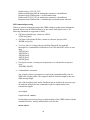
Figure 2: The GPRS entry on Setup Tab
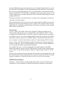
GPRS Properties
To access the dialog containing GPRS configuration properties, select the “GPRS” entry
and press “Edit”. The following dialog appears:
10
Figure 3: GPRS Properties Dialog
The GPRS Properties dialog contains setting for configuring the GPRS modem hardware.
Here are the options provided by this dialog:
Enabled
This property must be set to YES to enable GPRS processing, including self-timed and
alarm transmissions via GPRS and/or SMS communication, and command processing.
Port
This defines the serial port the GPRS device will be connected to. <None> will disable
GPRS support. To use a serial port for GPRS you will need to make sure it’s not already
in use for something else. The port settings are fixed at 115200,n,8,1. With RTS/CTS
hardware handshaking.
ModemAPN
The APN name is used to connect the modem to the internet. It varies based on the
provider of the cell service. For T-Mobile, a typical value is “telargo.t-mobile.com”
ModemUserName and ModemPassword
These are used to login to the cell service provider. For some providers they can be blank,
but otherwise use the value assigned by the provider or by Sutron.
ModemPIN
The SIM PIN unlock code. This must be specified if the SIM being used is locked. The
GPRS Diagnostics Tab will warn if a SIM PIN is needed and hasn’t been entered.
Entering the wrong PIN can cause the modem to become blocked, so be carefully
especially when swapping SIMs.
11
Radio Band
The Sutron GPRS modem supports multiple bands. Typically in the US the “Quad Mode”
can be used, but internationally you may need to select the specific band to prevent
frequency hopping and/or roaming. Normally, when a modem is connected to the Xpert
for the first time, it is factory reset and programmed to work with pre-configured settings.
The “Use Modem Setting” may be used to bypass this initialization and use the settings
that were pre-programmed in to the modem. This allows many of the modem settings to
be customized in the modem. The “Janus T2 Modem” and the “Sutron HSDPA Modem”
enables support for those specific 3G capable modems, but the settings are similar to
the “Use Modem Setting” in that they use the band(s) which have been pre-configured
in to the modem. If the default settings are unable to connect to the Cell provider,
custom settings may be needed, and the manual(s) for the modem should be consulted.
Typically the AT#BND and AT#AUTOBND need to be issued with the desired settings to
configure the appropriate bands, and then the AT&W command must be issued to save
the changes. Depending on the provider, some of the other settings such as
AT#PLMNMODE, AT#ENS, and AT#SELINT) may need to be checked or changed.
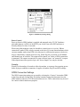
GPRS Power Settings
The GPRS power settings are accessed by selecting the “Power” item under GPRS in the
Setup tab and clicking Edit. This dialog contains settings that determine when the GPRS
modem should be powered on, how it should be powered on, and what it should do when
powered on.
Figure 4: GPRS Power Settings Dialog
PwrOnInterval + PwrOnTime + PwrOnDuration
PwrOnTime, PwrOnInterval, and PwrOnDuration are used to specify when the modem is
powered PwrOnInterval specifies how often to power on, PwrOnTime specifies an offset
to the interval, and PwrOnDuration specifies how long to stay powered.
For example, with PwrOnInterval = “01:00:00”, PwrOnTime = “00:30:00”, and
PwrOnDuration = “00:15:00”, the modem will be powered on every hour at half-past the
hour, and will stay powered for 15 minutes.
12
Also the GPRS modem generally needs to be reset to maintain health, which why even if
the PwrOnTime, PwrOnInterval, and PwrOnDuration specify essentially a never-ending
By powering on the GPRS modem the user is given the ability to communicate with the
Xpert over a TELNET, TCP/IP, SSP/CL, and SMS session via the master station. As well
as send self-timed, and/ or alarm transmissions (this can be done without the power mode
settings enabled too)
The primary reason to turn off the modem is to reduce power consumption, or limit time
connected to the Cell network.
Please note that if the LAN is powered on at the same time that the GPRS is powered on,
that the LAN will be preferred and may cause a conflict. This is similar to how when you
enable WiFi on a cell phone, communications will whenever possible be routed using the
WiFi interface and not the 3G.
PwrOnAction
If set to “Connect” the modem will use the “PrimaryIP” address and connect to the
master station using the port set for “Command Port” and establish an SSP/CL session
according to the PwrOn schedule. This mode is meant as an option for one way systems.
For example, if the user was using Tempest and didn’t know the IP address of the GPRS
modem but wanted to connect to it, the GPRS modem’s PwrOnAction would need to be
set to “Connect” in order for the modem to connect to Tempest using a SSP/CL session.
If set to “Listen” (the default setting) the modem will connect to any master station that
initiates a connection. This is as long PwrOnInterval, PwrOnTime, and PwrOnDuration
are set to power the GPRS at the time of this operation.
For example, if the user was using Tempest and knew the IP address of the GPRS
modem and wanted to connect to it, the GPRS modem’s PwrOnAction would need to be
set to “Listen” in order for the modem to connect to Tempest using a Telnet, or TCP/IP
session.
Finally if a user connects to the unit remotely with one of the ways mentioned above, and
the self-timed and /or alarm transmission fails to reach the master station the user will get
logged out regardless of what the user timeout value is set to in the user settings.
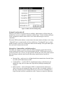
GPRS Relay Settings
The Relay… button brings up a further dialog which allows power to the modem to be
controlled by a relay connected to a digital I/O point and to control the warm-up time.
13
Figure 5: GPRS Relay Settings Dialog
Power Control
Power to Sutron's GPRS modem is supplied and managed using 12V DC (hardware
selectable jumper) via PIN 9 of the RS232 port. In this case select DTR and enter a
WarmUp delay of at least 10 seconds.
When using other modems it may be desirable to control power via a relay. When a
connection is made, DTR is always asserted to the device. For non-Sutron modems which
can enter standby mode when DTR is low this may be sufficient, but power to the device
may be controlled by a digital switch or relay. When Dig I/O is selected, an I/O Module
and Channel may be selected. This output will be turned “on” before a GPRS connection
is attempted. The output is assumed to be open-collector, hence “on” means 0V is output.
If the output instead uses positive logic, the “Invert Output” box may be checked.
WarmUp
WarmUp is the number of seconds to allow the modem to warm up after asserting power
before trying to establish a connection. It applies to both the Dig I/O and DTR settings.
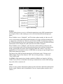
GPRS Connection Settings
The GPRS connection settings are accessed by selecting the “Connect” item under GPRS
in the Setup tab and clicking Edit. This dialog contains settings that determine how the
GPRS modem connects to TCP/IP based internet servers. These connections may be used
for control or data transmission purposes.
14
Figure 6: GPRS Connection Settings Dialog
PrimaryIP and SecondaryIP
Static IP’s and VPN access are not always available, which means it will not always be
possible for a server to establish a connection with the Xpert. To deal with this, the Xpert
can be configured to initiate contact with a server and send messages or wait for
commands.
When the GPRS modem initiates a connection to the master station, the Xpert tries using
“PrimaryIP” up to a certain number of times, and then try “SecondaryIP” up to a certain
number of times, with a few seconds pause between each attempt. The Xpert shall repeat
this cycle until a connection succeeds.
MessagePort, CommandPort, and RedirectorPort
The Xpert can connect to a master station for different purposes, and in order for the
master station (and firewalls) to sort out that purpose specific TCP/IP ports are used. If
you do not wish to use a service, you may specify 0 for the port value. The values entered
here should agree with the values used by the master station and any firewalls in
between:
Message Port – used to receive self-timed and alarm transmissions from the Xpert
in various ASCII data formats or SSP.
Command Port – used for SSP/CL command processing, so that the user can
change the setup, and view data in the Xpert directly through something like
Tempest.
Redirector Port – used for third-party SSP/CL communications redirected to
Xpert, so the user can change the setup, and view data. An example would be if
the user could not log onto Tempest directly, he or she can use something like a
HyperTerminal session to communicate to the Tempest to contact the Xpert unit.
15
ServerPassword
If not blank the GPRS Modem will use this password when accessing the server. This is
used for authentication purposes.
CSDShoulderTap
When enabled, CSDShoulderTap allows the user to call the modem using the phone
number given to the GPRS SIM card. The modem then will connect to what’s set to
“Command Port” as long the modem can connect to the “PrimaryIP” or “SecondaryIP”.
This gives the user another way of making the GPRS modem connect to a master station
such as Tempest.
The reason we have this settings is because if the user did not have a static ip address of
the GPRS modem but had the phone number of the GPRS, he or she can call the number,
or send a text with the command “STAP”. By calling the number, or sending the text, and
the Xpert is powering the GPRS using PwrOnTime, PwrOnInterval, and PwrOnDuration
the GPRS will create a SSP/CL connection to the master station even if the GPRS’s
PwrOnAction = Listen. If sending a text the user will receive a text message saying
“Created SSP/CL session to PrimaryIP(user set)”
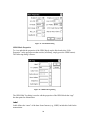
GPRS Transmission Settings
The GPRS transmission settings are accessed by selecting the “Transmit” item under
GPRS in the Setup tab and clicking Edit. This dialog contains settings that determine how
the GPRS modem transmits data to TCP/IP based internet servers.
Figure 7: GPRS Transmission Settings dialog
TxInterval
TxInterval defines how often to transmit self-timed messages. The format of the string is,
“hh:mm:ss”, where “hh” = hours, “mm” = minutes, and “ss” = seconds. For example,
“01:00:00” means “every hour”, while “00:30:00” means every half hourTypical rates are
01:00:00 for hourly transmissions and 04:00:00 for transmissions every 4 hours.
16
TxTime
This property defines an offet to TxInterval. It has the same format as TxInterval. A
TxTime of “00:15:00” means, “15 minutes after the hour”. Some examples of
transmission schedules are shown in the table, below:
TxInterval
TxTime
Transmission Schedule
01:00:00
00:00:00
12AM, 1AM, 2AM, …, 12PM, 1PM, 2PM, …
02:00:00
00:00:00
12AM, 2AM, 4AM, …, 12PM, 2PM, 4PM, …
01:00:00
00:30:00
12:30AM, 1:30AM, 2:30AM, …, 12:30PM, 1:30PM, …
04:00:00
00:15:00
12:15AM, 4:15AM, 8:15AM, 12:15PM, 4:15PM, …
TxFormat
This property defines the format of the data sent in self-timed transmissions (as well as
alarm transmissions when AlarmData = “AllSensors”). The following formats are
supported:
PseudoBin-B
6-bit “binary” format, interleaved
PseudoBin-B Non-Int
6-bit “binary” format, non-interleaved
PseudoBin-C
6-bit “binary” format, non-interleaved, with additional meta
data
SHEF
ASCII human readable format using SHEF codes
SHEFFIX
ASCII human readable format using SHEF codes, where data
appears in fixed width format of 7 chars
NIFC
ASCII human readable format based on NIFC requirements
NFRDS
ASCII human readable format based on NFRDS requirements
Handar
ASCII human readable format
SSP
Sutron Standard Protocol, binary format
Text
ASCII human readable text format, with alarm flags
See Appendix A – Telemetry Formats, for detailed definitions of each of the formats.
Num Values
When the selected format is interleaved (e.g., PseudoBin-B), the number of data values to
include for each selected data item must be the same for all selected items, and so is
entered in this dialog (rather than where it is normally entered, in the GPRS telemetry
block properties).
For example: if Num Values is 4, and GPRS blocks tag the two data points, “HG” and
“HF”, then the last 4 values of HG and HF appear in the transmit message.
17
AlarmData
AlarmData can be either “SensorsInAlarm” or “AllSensors”. When set to the latter, alarm
transmissions contain the same data as is found in self-timed transmissions, i.e., all data
tagged with an GPRS block in the Graphical Setup (as well any data ponts tagged in
EzSetup). However, when AlarmData is “SensorsInAlarm”, only the data triggering the
alarm is included in the transmission.
Content
When you press the Content button on the GPRS Transmission Settings dialog, the “Set
Tx Content” dialog opens showing a list of all GPRS blocks in the Graphical Setup (as
well as any data points tagged in EzSetup).
Figure 8: Select Tags dialog
When more entries exist than can be shown in the dialog, scroll bars appear, allowing you
to scroll to other entries.
From this dialog, you can change the value of the “TxContent” property for each data
item in the list. You can also press the “…” button to access and change other properties
in the block’s properties dialog.
GPRS SMS Settings
The GPRS SMS settings are accessed by selecting the “SMS” item under GPRS in the
Setup tab and clicking Edit. This dialog contains settings that determine how the GPRS
modem transmits manages sending and receiving SMS text messages.
18
Figure 9: SMS Settings
TxMode
TxMode allows the user to receive self-timed transmissions using SMS communication.
An example of this is when wanting to receive self-timed transmissions through your
phone.
When TxMode is set to “Scheduled”, and TxList has a phone number in it the user will
receive text messages with self-timed transmissions every time a self-timed transmission
is supposed to occur based on TxInterval, and TxTime in GPRS Transmission settings. If
the self-timed transmission does not get through to the master station, the SMS self-timed
transmission will be delayed due to the retries, but will still be attempted.
When TxMode is set to “Fallback”, and TxList has a phone number in it the user will
receive text messages with self-timed transmissions every time a self-timed transmission
doesn’t get through to the master station using the GPRS link. While it’s not always
possible there are circumstances where a GSM SMS text message can get through when a
GPRS data transmission cannot.
The format of the SMS self-timed transmission will be based on the TxFormat set in
GPRS settings. Expect if the format is “SSP” due to it being in binary – in that case
“Text” will be used.
CAUTION: SMS transmissions whether scheduled or fallback are limited to 160 bytes
of data. Users will have to limit their data sent per transmission or else the SMS message
may not be able to contain it all.
TxList
Allows to user to choose what phone numbers get the self-timed, and alarm transmissions
based on what TxMode, and/or AlarmEnable is set too. Separate phone numbers with a
comma “,”.
19
Alarms
When Alarms is checked and TxList has a phone number in it, the Xpert shall also send
alarm messages via SMS. The SMS message is human readable, and includes the station
name so the user does not need to know the station identified by the phone number. The
time is also included to account for the delays in delivery. The date is not included as the
delays are expected to be short. The alarm transmissions format of what sensor data gets
sent is based on whether the user set AlarmData to “All Sensors”, or “Single Sensor”.
An example of the Text format used for SMS alarm messages:
RTU01 12:22<cr><lf>
STAGE 4.55 G H+R+<cr><lf>
RAIN 2.0 G OK<cr><lf>
The message begins with the station’s name (“RTU01”) and the current time in HH:MM
(12:22) format followed by a list of sensor readings containing the name of the sensor
(“STAGE”), the value (“4.55”), the quality (“G”), and the alarm status (“H+R+”).
In the above example "H+R+" indicates that STAGE is experiencing a high limit and
high rate of change alarm, while the “OK” status for RAIN indicates that it is within
expected limits.
Quality codes:
G: Good quality
B: Bad quality
U: Undefined quality
Alarm codes:
H: High limit exceeded
L: Low limit exceeded
R: High Rate of change
OK: Normal
A “+” after a code indicates that the sensor has just entered that state, while a “-“ after a
code indicates that the sensor has just exited that state.
CAUTION: SMS alarm transmissions are limited to 160 bytes of data. Users will have to
limit their data sent per transmission or else the SMS message may not be able to contain
it all.
Notify
The Xpert shall report the following events via SMS to the list of phone numbers in
NotifyList:
Station Rebooted – Indicates that the Xpert unit has rebooted
20
Recording on/off – Indicates that the Xpert unit has turned recording on
(Recording on), or recording off(Recording off)
GPRS connect failure - Indicates that GPRS services may not currently be available (a
given cell tower may support GSM/SMS services but not GPRS), or that there’s
something wrong with the APN settings, the account, the provider, etc.
Shoulder tap failure - If GPRS is unable to perform a shoulder tap that’s been
requested by the user using SMS, the command line, or by ringing the cell modem
(CSDShoulderTap=Yes), then it should send an “STAP failed (could not
connect)” SMS notification message. The shoulder tap requires making a TCP/IP
connection to the IP and port specified by the command or the primary IP and
command port if other settings were not supplied.
NotifyList
Allows to user to choose what phone numbers get the SMS notification for
SMSNotifyEnable’s events. Separate phone numbers with a comma “,”.
SetupPassword and DataPassword
These two properties specify authorization codes used to validate incoming command
messages. SetupPassword specifies the authorization code for “setup-level” access, while
DataPassword specifies the authorization code for “data-level” access.
Incoming command messages have setup-level access by default. When the
SetupPassword property contains an authorization string, any and all incoming messages
that normally require setup-level access to be processed must prefix the command with
the authorization code. For example, to command the station to reboot with an
authorization code of “MyAuthCode”, the incoming message content would be
“MyAuthCode reboot”.
SetupUserList and DataUserList
These two properties are authorization settings that require the phone number stated in
the Authlist to be used to validate incoming command messages. Both SetupUserList and
DataUserList are only enabled in addition to the SetupPassword and DataPassword being
enabled.
A better explanation about how it’s used is if the SetupUserList property specifies a
phone number, while SetupPassword is blank, then a user from any phone number can
send a setup command with no code, and the command will be processed. However if
SetupUserList property is blank, while SetupPassword has a code, then the user must
have the code, regardless of his phone number.
For example if he or she wants to send the reboot command he or she needs to use the
SetupPassword string, as well send the SMS message with command from the phone
number listed in SetupUserList.
SMS command = Reboot
SetupPassword = sutron
21
SetupUserList = 555-555-5555
Phone used(888-888-8888) & sending the command = sutronReboot
Response from GPRS modem = invalid authorization
Phone used(555-555-5555) & sending the command = sutronReboot
Response from GPRS modem = command processed and system rebooted
SMS command processing
If the user wants to change the setup in the GPRS settings or gather status information
about the Xpert from the GPRS modem he or she can use their phone to do it. The
following commands are supported via SMS:
Call home (shoulder tap): connect to SSP/CL
-STAP [url[:port]]
Call home with optional IP/Port: connect to redirector port specified
-REDIR [url[:port]]
To set (or show if a setting isn't provided) the PrimaryIP, SecondaryIP,
MessagePort, CommandPort, RedirectPort. The URL and PORT values are user
input
-SETPIP [url]
-SETSIP [url]
-SETMP [port]
-SETCP [port]
-SETRP [port]
Check power status, or turn power temporarily on or off until the next power
cycle:
-POWER [ON|OFF]
Command-line commands
Any responses that are generated as a result of the command shall be sent via
SMS to the original sender. The responses shall be limited in length by the max
SMS message length.
Also if the SetupPassword, and/or DataPassword are enabled, the user must type
the authcode string before the command in order for authorization of the
command to happen.
An example:
SetupPassword : sutron
On the phone send a text message to phone number of the GPRS modem with the
command “Reboot” and the authentication code like this:
sutron reboot
22
Also if the SetupUserList is enabled the user must send the command with the
authorization code from that specific number listed in the SetupUserList. But be
aware that if there is no SetupPassword enabled, then it doesn’t matter if
SetupUserList has a phone number because the user can send the command from
any phone and change the setup of the GPRS modem.
This functionality was setup for a user that couldn’t communicate with the GPRS
over VPN or Public IP. It gives the user the almost the same abilities as if he or
she were using the master station to communicate to the GPRS modem.
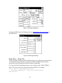
Selecting Data for Transmission with the GPRS block
Sensor data can be tagged for transmission in two ways using either the Graphical Setup,
or the EzSetup. The properties are the same, whether you are working in the Graphical
Setup or EzSetup.
Using the Graphical Setup, you need to attach a GPRS block (found under the Telemetry
category) to an output you’d like to have transmitted, and then configure the block.
Here’s an example of the order we suggest that the blocks be created and connected
together:
Figure 10: GPRS block in Graphical Setup
In the setup depicted above, the GPRS block tags a measured data point, that of, Air
Temp (AT). Here are some important notes about the setup:
The GPRS block appears after Alarm block. This ensures the GPRS block “sees”
the result of the alarm evaluation, triggering alarm transmissions, if needed. Of
course, the Alarm block is only required if your system will evaluate data for
Alarm and/or alarm transmissions.
The GPRS block appears before the ComsTag block. This ensures the ComsTag
“sees” the alarm transmission status generated by the Alarm and GPRS blocks.
The ComsTag block is required for SSP telemetry, but even when not using the
SSP format it allows the value to be displayed on the Data tab and/or accessed via
the command prompt and SMS commands.
Alarm Block Properties
The Alarm block is a standard block used to define high limits, low limits, and rate of
change. The block is discussed in detail in the Xpert manual, but one interesting feature
to note is that Alarm blocks may be stringed together to handle multiple conditions.
23
Figure 11: Alarm Block Dialog
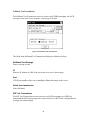
GPRS Block Properties
To view and edit the properties of the GPRS block, tap the block and select “Edit
Properties” in the pop-up menu that results (in EzSetup, simply press the GPRS button).
The following dialog is shown:
Figure 12: GPRS Edit Tag Dialog
The GPRS Edit Tag dialog is used to edit the properties of the GPRS block that “tags”
the data point for transmission.
Label
Label defines the “name” of the data. Some formats (e.g., SHEF) include this Label in the
transmission.
24
TxContent, DataInterval, DataTime, NumValues
These properties define what data to include in the transmission. See the following table
for details:
Tx Content
All
Individual
Data Interval
Data Time
Num Values
Last
Exclude
Description of data to transmit
All the data logged for the output since the
last transmission will be transmitted
Individual values logged for the output since
the last transmission will be transmitted.
The time interval between readings. For
example, “01:00:00” means “hourly data”
The time, or offset into the interval, of the
data to include. For example, “00:15:00”
means “include data measured on a 15 minute
offset”
Number of values for each data item to
include in the transmission
Only the last value measured will be
transmitted
Do not transmit this output
Sequence
This property determines the order of the data item within the transmission.
Right Digits
This property determines the number of right digits to include in the transmission.These
properties determine what data is included in transmissions, and its sequence in the
transmission (if applicable to the selected format). The value of Tx Content can be All,
Individual, Last, or Exclude as described below. Setting Tx Content will enable or
disable other properties:
Note: When Pseudobinary B (an interleaved format) is the selected format, the user
defines a Num Values setting for all outputs in the GPRS Transmission Settings Dialog,
and the meaning of the Tx Content property on each output changes: A Tx Content value
of “Last” no longer means just the last value, but the last Num Values values. A Tx
Content value of “All” no longer means all values since last transmission, but all values
up to Num Values.
Tagging Data with EzSetup
Tagging data for GPRS transmission in EzSetup requires placing a check next to the
GPRS button and then pressing the GPRS button to select the properties.
25
Figure 13: EzSetup Configuration
Pressing the GPRS button will bring up the same GPRS Block Properties Dialog as
described above:
Figure 14: GPRS Tag in EzSetup
Basic Entry – Setup Tab
A Basic program can format custom GPRS messages. Any of the Basic string functions
can be used to format the buffer as required, but the Bin and Bin6 functions exist
specifically to help forming 8-bit and 6-bit binary encoded data.
To create a self-timed formatting routine, create a function with a "SELFTIMED_"
prefix. The return value of the function becomes the buffer. For example:
Public Function SELFTIMED_STFormatter
Selftimed_STFormatter = "Test Selftimed Message"
End Function
26
To create an alarm formatting routine, create a function with an “ALARM_” prefix and a
single parameter in which the group number will be passed. The return value of the
function becomes the buffer. For example:
Public Function ALARM_Formatter(Group)
ALARM_Formatter = "Test Alarm Reporting Message: " +
Str(Group)
End Function
It's possible to append to the buffer, as opposed to simply overwriting it, by taking
advantage of string concatenation. The following example appends its message to the
current buffer:
Public Function SELFTIMED_STFormatter
SELFTIMED_STFormatter = SELFTIMED_STFormatter + "Test
Selftimed Message"
End Function
More than one formatting function can exist in your program, but only one self-timed and
one alarm function may be active at one time. The active routine is selected in the Iridium
Custom Formatting entry under Basic, on the Setup tab:
Figure 15: GPRS Custom Formatting Entry
27
TESTING GPRS OPERATIONS
This section describes how the GPRS Diagnostics Tab may be used to test out GPRS
communications.
The GPRS Diagnostics Tab
The GPRS Diagnostics Tab may be used to test communications over GPRS, and
examine the communication status.
Figure 16: GPRS Diagnostics Tab
Modem status
Modem status describes the current state of GPRS processing, and may be any one of the
values in the following table:
Status
Description
Alarm Tx
Alarm transmission in progress
App Stop
System is being shutdown
Comm Error!
An error has occurred talking to modem (check connection to modem)
DailyMaint
System is storing and resetting daily counts
Disabled-Off
GPRS is disabled and off
Disabled-On
GPRS is disabled, but power is still on
Force Power Off The “OFF” button was pressed in the GPRS Diagnostics Dialog
Force Power On
The “ON” button was pressed in the GPRS Diagnostics Dialog
GPRS Denied
A connection to the GPRS network could not be made
GPRS Ignore
A GPRS connection could not be established, and the Xpert is moving
28
forward with GSM support, but will still try to establish a GPRS
connection as needed
GPRS Ready
GPRS is registered
GPRS Roaming
GPRS could not establish a connection to the home network and is
currently roaming on a partner network.
GPRS Search
GPRS is still trying to establish a connection to a tower
GSM Denied
A connection to the GSM network could not be made
GSM Ready
GSM is registered
GSM Roaming
GSM could not establish a connection to the home network, and is
currently roaming on a partner network.
GSM Search
GSM is still trying to establish a connection to a tower
Modem Chg
A change to the modem settings has been made and is being applied
Power Off
Modem is powering off
Power On
Modem is powering on
Property Chg
A setup change is taking effect
Reconnect
A GPRS connection unexpectedly dropped and is being reconnected
Reschedule
A setup change requires events to be rescheduled
SelfTimed Tx
Self-timed transmission in progress
Send Alarm
An alarm tx is being scheduled
SMS Notify
An SMS notification message is being sent
SSP/CL Chg
A change to the SSP/CL and/or Transmission settings has been made
and is being applied
Standby-Off
Modem is not powered, and is ready for next task
Standby-On
Modem is powered up due to the power settings, and is ready for next
task.
Standby-On*
Modem is powered up to handle a temporary condition such as
transmission outside the normal power-up cycle, an alarm
transmission, or a call back operation.
Starting
System is starting up
Stopped
GPRS processing has stopped (no transmissions will occur)
Stopping
System is stopping
In addition while a GPRS network connection is being established there are additional
status messages that may be display during the process as follows:
29
Network Connection Status
Description
All Devices Connected
A network link has been established
Authenticated
The network link has been authenticated
Authentication Acknowledged
A request for authentication is being acknowledged
Authentication Notify
Authentication is needed
Authentication Retry
Authentication with different credentials has been
requested
Connected
Network connection has been established
Connecting Device
A connection is about to be started
Device Connected
A connection has been made to the modem (not the
network)
Device Setup
The modem port is being configured
Disconnected
The connection has been terminated or failed
Opening Port
The modem port is being opened
Password Expired
Password has expired
Retry Authentication
Retrying authentication
Starting Authentication
Authentication is being performed
Tests…
Pressing this button will bring up the GPRS Test Dialog (see below).
Next task
The next task that’s scheduled to occur and may be: Nothing, DailyMaint, PwrOff,
PwrOn, Reschedule, SMSNotify, SelfTimed, Alarm, Reconnect, or AppStop.
Next task time
Contains the time that the next task is scheduled to start
Time
The current time is displayed as a reference
Last SMS
Displays the last SMS text message received
30
More…
If multiple text messages have been received, pushing this button will display the last 5.
Signal Quality
Displays the last measured cell signal strength in terms of bars, or in dBm with % bit
error rate. The dBm value can range from -51 (strong) to -113 (weak). For reference -75
is considered “5 bars”, and -105 is considered “2 bars”. The bit error rate will vary from
0.2% (best) to 12.8% (worst). Often the bit error rate is a better indicator of quality than
signal strength.
Update
Pressing the Update button will cause the signal strength to update for 2 minutes or until
the button is pressed again. As it updates, a tone is output by the Xpert that’s proportional
to the signal strength. The higher in frequency, the better the signal. This can be used to
aid in aiming the antenna.
ON
Pressing “ON” turns the GPRS radio on until the next scheduled off time.
OFF
Pressing “OFF” turns the GPRS radio off until the next scheduled on time. GPRS will
still turn on as needed for transmissions.
Selftimed statisitics…
Displays the following information about self timed transmissions:
Last Tx, #Tx Today, Next Tx Time, Next Tx msg, Next Tx size, Est #Tx bytes/day, and
#Tx bytes today.
The estimate #Tx bytes/day can be used to help estimate the data budget for a station, but
as it doesn’t include overhead it will be significantly low.
Alarm statistics:
Displays the following information about alarm transmissions:
Last Tx, #Tx today, #Tx bytes today.
GPRS Test Dialog
The GPRS Test Dialog is used to send test transmissions using SMS, Selftimed, or SSP
messaging. Select the type of transmission, enter a test message (and other related
information), and press Send.
31
SMS Test Transmission
The SMS Test Transmission screen us used to verify SMS text message operation. SMS
messaging requires GSM services – which may operate in areas where GPRS service is
not available.
Figure 17: SMS Test Transmission
The fields in the SMS Test Transmission Dialog are defined as follows:
SMS Test Message
Enter a message to send.
Phone
Enter the phone number to send the SMS message.
Send
Send the message
Last
The last SMS message received
More
The last 5 SMS messages received
Select test transmission
Select SMS
32
Selftimed Test Transmission
The Selftimed Test Transmission screen is used to verify GPRS messaging. An ASCII
message is sent to the server using the “session type 0” header.
Figure 18: Selftimed Test Transmission
The fields in the Selftimed Test Transmission Dialog are defined as follows:
Selftimed Test Message
Enter a message to send.
IP
Enter the IP address or URL of the server that is to receive the message.
Port
TCP/IP port number of the service handling Selftimed messages on the server
Select test transmission
Select Selftimed
SSP Test Transmission
The SSP Test Transmission screen us used to verify SSP messaging over GPRS, by
transmitting an SSP mail message to the specified server (or RTU) and verifying that the
message was acknowledged.
33
Figure 19: SSP Test Transmission
The fields in the SSP Test Transmission Dialog are defined as follows:
SSP Test Message
Enter a message to send.
IP
Enter the IP address or URL of the server (or RTU) that is to receive the message.
Port
TCP/IP port number of the service handling SSP messages on the server. The default SSP
service on an RTU is the Telnet service which used port 23.
Send
Send the message
Last
The last SSP message received
More
The last 5 SSP messages received
Select test transmission
Select SSP
34
TROUBLESHOOTING
1. Did you check to make sure that Remote, Coms, Basic, or any other part of the
system isn’t trying to use the com port you wish to use for GPRS? Issuing
“status” at the command prompt will list all ports that Remote has been
configured to support.
2. Did you check to make sure the LAN device is turned off?
3. If you just configured a serial port for the first time, have you tried rebooting the
unit?
4. Observe the GPRS Diagnostics Tab while a connection is attempted and verify
that connections are being scheduled, and watch for an issue during the
connection negotiation.
5. Verify that the GPRS device is being powered up correctly by pressing ON in the
GPRS Diagnostics Tab.
6. Issuing “report high” or even “report debug” at the command prompt is a good
way to get real time diagnostic information about the performance of the GPRS
SLL and the system in general. You can monitor SSP messaging by issuing
“report ssp”. SSP over TCP/IP messages may be viewed by issuing “report ssp0”,
or the options may even be combined by issuing “report ssp ssp0”.
7. The system status page will show information about the most recent diagnostic
messages and the current state of the GPRS device. This can also be displayed on
demand at the command prompt with the “info” command.
8. The system.log can be examined to look for status messages, connection errors,
and transmission errors.
9. Use the GPRS Diagnostic page to send test mail messages.
10. If you need to reach your station for maintenance, but it’s configured to turn on
only when transmitting, you may try sending the SMS command “POWER ON”
to the station. The SMS command won’t be able to go through while the modem
is powered off, but it may get through on a retry or if you happen to time it for
when the station is transmitting.
11. Contact Sutron Customer Support at 703-406-2800.
35
APPENDIX A – TELEMETRY FORMATS
This appendix contains descriptions for each of the telemetry formats supported by Xpert
Iridium.
Handar Format
The Handar format is an ASCII, human readable format where sensors are separated by
<CRLF>, sensor data is separated with a space, and missing data is reported as “M”.
For example:
010034380517419:21:30G42+0NN155E9200070"
1.3 1.3 1.3 1.3
2.4 2.4 2.4 2.4
M 12.2 12.2 12.2 12.2 12.3 12.3 12.3
NFDRS and NIFC Formats
The NFDRS (National Fire Danger Rating System) and NIFC (National Interagency Fire
Center) formats produce reports of human readable ASCII values using SHEF codes as
labels for data.
The labels applied to measurement outputs are used to identify the data to include in the
report. The following table shows what labels are recognized be the NIFC and NFDRS
formatter. An “x” means the sensor label must appear in the setup for the formatter to
succeed. The items with no “x” are recognized and will be formatted, but are not
required.
Sensor
Label
NIFC
NFDRS
Rainfall
PCH
x
x
10-Min Avg Wind Spd
USH
x
x
10-Min Avg Wind Dir
UDH
x
x
Air Temperature
TAH
x
x
Fuel Temperature
MTH
x
10-Min Avg Rel Hum.
XRH
x
x
Battery Voltage
VBH
x
x
Barometric Pressure
PAH
Peak Wind Direction
UGX
Peak Wind Speed
UPH
36
Fuel Moisture
MMH
Solar Radiation
RDH
x
Here’s an example NIFC telemetry report:
00.00
000
270
328
110
100
14.0
000
000
020
0486
Here’s an example NFDRS telemetry report:
00.00
000
270
328
110
100
14.0
000
000
020
0486
Note how there are no labels in the report. This is because the position of the data within
the report determines the source of the data.
37
Pseudobinary Formats
Pseudobinary formats produce ASCII reports of 6-bit pseudo-binary formatted data
values. The formats are “pseudo”-binary, because each sensor value is expressed in the
range of ASCII characters, but not in such a way that is readily human-readable.
Pseudobinary B (Interleaved and Non-Interleaved)
The Pseudobinary-B Interleaved format is identical to the 8210 binary transmission
format. “Interleaved” means the most recent values of all sensors come first, followed by
the next most recent, and so on. “Non-interleaved” means all the data for sensor 1 is
followed by all the data for sensor 2, and so on, i.e., the data is not “interleaved”
according to time.
This pseudobinary format cannot be easily read by a person. Here’s is an example
message:
B1@@Gt@Sx@@i@Gs@Sr@@iI
Battery Voltage
Temp #2
Precip #2
Stage #2
Temp #1
Precip #1
Stage #1
Delta Time
Group ID
Block ID
Pseudobinary-B Format
Name
Bytes
Description
Block ID
1
BLOCK-IDENTIFIER is always sent as "B" to
indicate that this is the pseudobinary B format.
Group ID
1
GROUP-ID can be "1" to indicate a scheduled
transmission, “2” meaning an alarm transmission,
and “3” indicating a forced transmission.
Delta Time
1
Age in minutes of the most recent data
Data
3x num
sensors
Data in either interleaved, or non-interleaved
format. The example above shows the data
interleaved (most recent of all sensors followed by
next oldest, and so on). See the section below,
“Six-Bit Binary Encoded Format” for details on
how these values are encoded.
38
Battery
Voltage
1
Logger battery voltage measured just prior to
transmission
Pseudobinary-C Format
The Pseudobinary-C format also produces an ASCII report of 6-bit pseudo-binary
formatted values, but with additional fields to describe label and time information. Just as
the “B” version of the format, this format is “pseudo”-binary, because each sensor value
and descriptor is expressed in the range of ASCII characters, but not in such a way that is
readily human-readable.
Pseudobinary-C Format
Name
Bytes
Description
Block ID
1
BLOCK-IDENTIFIER is always sent as "C" to
indicate that this is the pseudobinary C format.
Group ID
1
GROUP-ID can be "1" to indicate a scheduled
transmission, “2” meaning an alarm transmission,
and “3” indicating a forced transmission.
Measurement
Delimiter
1
This byte is always a “+” and it is used to denote
the start of measurement data.
Measurement
Index
(Sequence)
1
The Sequence number assigned by user in the
output telemetry settings. This value is encoded 6
bit binary. Typically, the sequence number assigned
is unique, allowing you to uniquely identify the
data point.
Day
2
This 2 byte encoded 6 bit binary encoded number
represents the Julian day of the year. The day tells
when the most recent (first) sensor reading of this
measurement was made.
Time
2
This 2 byte encoded 6 bit binary encoded number is
a number of minutes into the day. It tells when the
most recent (first) sensor reading of this
measurement was made.
Interval
2
This 2 byte encoded 6 bit binary encoded number
tells the measurement interval in minutes, or the
amount of time between readings of this
measurement.
Measurement
Data
3 for each
sensor
reading
Sensor data encoded 6 bit binary.
Additional
Variable
If more than one measurement was setup for
39
Measurements
transmission, more data will follow. Each
measurement setup will have data starting with the
Measurement Delimiter and ending with
Measurement Data.
Final
Delimiter
1
This byte is always “.” and it is used to denote the
end of all measurement data.
Battery
voltage
1
This is the battery voltage measured prior to
making the transmission. The range of the number
will be -32 to +31 and can be converted to volts by
multiplying by 0.234 and adding 10.6 allowing a
range of 3.1 to 18.1 volts.
Example Pseudobinary-C message:
C3+ADGTU?///+BDGTU?@UI+CDGTU??~v///.L
Group
3 format C
Sequence
A
1
Julian Day
DG
263
Time
TU
21:41
Interval
?
00:-1
Data:
/// missing
Sequence
B
2
Julian Day
DG
263
Time
TU
21:41
Interval
?
00:-1
Data:
@UI 1353
Sequence
C
3
Julian Day
DG
263
Time
TU
21:41
Interval
?
00:-1
Data:
?~v -74
/// missing
Batt V
L
13.4
Six-Bit Binary Encoded Format
The six bit binary format is used to encode numbers into displayable ASCII characters.
Notice that fractional numbers cannot be represented, so for instance a battery voltage of
13.04 volts set up with 2 right digits will be sent as 1304.
A 1 byte encoded number can range from -32 to +31.
A 2 byte encoded number can range from -2048 to +2047
A 3 byte encoded number can range from -131072 to +131071
Binary encoded numbers are always sent most significant bytes first. The number itself is
broken down into 6-bit digits, and each digit is placed in one byte of data. The number
64 (ASCII "@") is added to each digit to make it fall within the range of displayable
40
ASCII characters. The only exception is that 127 (ASCII <DEL>) is sent as 63 (ASCII
"?")
Example 1. Encoding the number 10 in 1 byte:
Since 10 will fit in 6-bits we only have to add 64 which would yield 74. So the number
10 would appear as ASCII 74 or the letter "J".
Example 2. Encoding the number 12345 in 3 bytes:
First we have to convert 12345 into binary in 6-bit pieces:
12345 (base 10) = 11 000000 111001 (base 2)
Now we can convert each piece back to base 10:
11 000000 111001 (base 2) = 3, 0, 57
Finally, we add 64 to each piece and convert to ASCII:
67, 64, 121 = ASCII "C@y"
Example 3. Encoding the number -12345 in 3 bytes:
First we have to convert -12345 into two's complement 18-bit binary: -12345 (base 10) =
111100 111111 000111 (base 2)
Now we can convert each piece back to base 10: 111100 111111 000111 (base 2) = 60,
63, 7
Finally, we add 64 to each piece and convert to ASCII (since the second piece is 63 we
leave it alone):
124, 63, 71 = ASCII "|?G"
Example 4. Decoding the 3 byte string "@SW":
This is just like encoding except we follow the steps backward.
First we convert all the characters to ASCII decimal codes:
ASCII "@SW" = 64, 83, 87
Now we subtract 64 from each piece and convert to 6-bit binary:
0, 19, 23 = 000000 010011 010111
Finally, we combine all the bits to form one 18-bit two’s complement number and
convert to base 10:
000000010011010111 = 1239
Pseudobinary-B/C over SMS Format
The Pseudobinary-B and -C formats contain 8 characters which cannot be sent over SMS
using the standard GSM 7-bit character set without inserting additional characters. This is
undesirable as it would reduce the number of bytes that can be sent over SMS from 160
to 80 (in the worst case). To work around this limitation, SMS messages that contain a
Pseudobinary message will automatically be translated to replace non-supported
41
characters with supported characters. Please note that this requires that the characters be
translated back upon reception and before they can be passed to a decoder.
The following table describes the character translation that’s performed:
ORIGINAL
HEX
5B
5C
5D
5E
60
7B
7C
7D
7E
CHAR
[
\
]
^
`
{
|
}
~
REPLACEMENT
HEX
31
32
33
34
35
36
37
38
39
CHAR
1
2
3
4
5
6
7
8
9
SHEF and SHEFFIX Formats
“SHEF” format conforms to NESDIS Standard Decimal format specifications. The
format is ASCII and readable by persons without the aid of a computer.
The standard decimal format is human readable while binary formats require some
processing before the values can be read. The standard decimal format is generally twice
as long as the binary transmission. This means that less data can be sent in the same
amount of time using the standard decimal format.
An example of a standard decimal format message is shown below. This message comes
from a station with three sensors in the self-timed group. The sensors have been named
HG, PC and TA. The battery voltage is the voltage of the battery just prior to
transmission.
:HG
0
#15
10.20
10.15
:PC
0
Precip
#15
50
49
:TA
0
Temperature
#15
-22.1
-22.0
Battery
Older gauge reading (by data interval time)
Newest gauge reading
Data Interval
Offset Time
Gauge Height
The names HG, PC, TA and VB used in the transmission are called SHEF Physical
Element codes (PE codes) and are the names given to the outputs in the 8310. Be sure to
change the output names if you want specific codes sent in the transmission. NESDIS
has a recommended list of SHEF PE codes on its website at
http://noaasis.noaa.gov/DCS/htmfiles/schefcodes.html
42
:VB
0
1
“SHEF Fixed” is a special version of the SHEF format where numbers are fixed to seven
decimal points.
SSP Format
“SSP” is a binary format following the specifications of the Sutron Standard Protocol,
which is useful when transmitting to XConnect or Tempest master stations.
If you are interested in knowing more about the low-level details of the protocol, please
contact Sutron Customer Service.
Text Format
The Text format is an ASCII, human readable format intended to convey the current
status of the sensors, quality, and alarm state. It is similar in format to the “SHOW”
command, and is intended for alarm messages. It’s also the default format for SMS
Alarm messages when SMSAlarmsEnable are enabled. Sensor readings are separated by
<CRLF>, while fields in the sensor data are separated with a space.
An example of a Text format message:
RTU01 12:22<cr><lf>
STAGE 4.55 G H+R+<cr><lf>
RAIN 2.0 G OK<cr><lf>
The message begins with the station’s name (“RTU01”) and the current time in HH:MM
(12:22) format followed by a list of sensor readings containing the name of the sensor
(“STAGE”), the value (“4.55”), the quality (“G”), and the alarm status (“H+R+”).
In the above example "H+R+" indicates that STAGE is experiencing a high limit and
high rate of change alarm, while the “OK” status for RAIN indicates that it is within
expected limits.
Quality codes:
G: Good quality
B: Bad quality
U: Undefined quality
Alarm codes:
H: High limit exceeded
L: Low limit exceeded
R: High Rate of change
OK: Normal
A “+” after a code indicates that the sensor has just entered that state, while a “-“
after a code indicates that the sensor has just exited that state.
43
GPRS Session Protocol
GPRS follows a protocol when sending self-timed and alarm transmissions that permits
the server to issue commands. This protocol is often referred to as, “Session Type 0”. The
protocol helps support communications to a device which has a non-routable IP address,
as many IP cell modems provide. Session Type 0 does not apply to SSP transmissions.
The following is a description of the protocol:
Course of Events
1. Logger connects to Main or Backup Server
2. Logger sends Session Type Code<cr> (see below)
3. Logger sends StationName<cr>
4. Logger sends Report Type Code<cr> to indicate purpose of connection (see
below)
5. Logger sends scheduled (or alarm) transmission data (if any)
6. Logger sends ETX (0x03) to mark end of data
7. Logger sends a 3 byte pseudobinary encoded CRC16 of previous data and a
shared secret
8. Server sends user login command, !login=username,password<cr> and waits for
logger reply (ETX)
9. If user login matches, logger enters command-line session (see operational details,
below)
10. Server issues pending commands, and Logger processes and responds accordingly
11. When command processing complete, the Server disconnects
Session Type Code
"Session type" defines the processing that occurs on connection. Currently, there is only
one session type, "0". This type is defined by the Course of Events above, and details that
follow.
"0" = defined by Course of Events, above
Report Type Code
“Report Type code” describes the purpose of the transmission:
"0" = self-timed
"2" = entering alarm
"4" = exiting alarm
"6" = no data, command session only
Command-line Session Details
44
The server may precede each command with a "!" to signal machine mode
When processing a command in machine mode, the logger:
Suppresses the command echo
Uses ETX (0x03) as the command prompt (i.e., follows the command response
with ETX, rather than the normal command prompt)
Inhibits pagination (doesn't pause to wait for user input after outputting a full
"page" of data)
Alternate Paths
Following send of ETX, logger disconnects the user specific timeout.
Sixty (60) seconds is permitted for login. Logger disconnects on failed login.
45