1
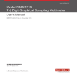
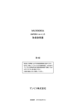
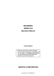
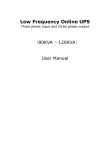
WindMonitor
User Manual
Ver 4.1
2 of 46
Contents
1. Introduction
2. Notes
3. Overview
4. Quick start
5. Hardware
6. Software
7. Configuration software
8. Connecting sensors
9. Technical specifications
10. Quick reference
5
5
7
9
11
19
29
37
41
43
3 of 46
4 of 46
1. Introduction
Wind measurements has been started over one hundreds years ago. Methods and
instruments for measuring during that time changed significantly. The fact that wind data are
still more and more important results that there are various specifically designed devices for
this purpose.
WindMonitor is designed for precision measurements of wind data (wind speed, wind
direction) and additional complementary data (ambient temperature, relative humidity,
atmospheric pressure and user defined sensors). The main effort is oriented to wind
measurements with calculation of mean, minimum, maximum values and standard deviation.
All of this is strictly compliant with IEC 61400-12-1 norm – for wind farm monitoring
stations.
The instrument was designed by team of professionals with long time experience in
low level and noise signals, software microprocessor programming and oriented to datalogger
and sensors for extreme weather conditions. Employing latest high technology we are proud
to present you measuring system, which is simple in use, but offers high precision
measurement and all features which are expected from today’s wind dataloggers. It is
configurable by the user by simple set of commands or PC configuration software. The
applications range from meteorology, metrology, environmental monitoring, industry,
research, use in school and laboratory.
2. Notes
Before starting to work with WindMonitor it is recommended to read this manual!
Manufacturer reserves the right to upgrade specifications without prior notice.
In the case you have questions or comments, please, contact manufacturer at the
following address:
Adolf Thies GmbH & CO. KG
Hauptstraße 76
37083 GÖTTINGEN
Germany
Tel: +49-551 79001-0
Email: [email protected]
Copyright Adolf Thies 2011. All rights reserved. This manual, or its part, can not be
reproduced or distributed in any form without prior written approval from the manufacturer.
5 of 46
6 of 46
3. Overview
WindMonitor is designed for measuring, processing, recording (datalogging) to the
memory of measured data in real time for the needs of wind farm applications and further
analyses. The instrument is designed especially with intention to precision, low power
consumption and comfortable, user friendly operation. It employs five wind speed inputs,
(configured for frequency measurement), three wind direction inputs (configured for analog
input measurement with 12 bit resolution), one ambient temperature input (analog with 24 bit
resolution and 4-wire PT100 configuration), one relative humidity input (analog with 12 bit
resolution), ambient pressure input (analog with 12 bit resolution) and two universal inputs
(analog, single ended with 12 bit resolution). In addition, there is possibility to connect
ThiesClima gray code serial wind direction sensors as well as ThiesClima RS485 serial wind
speed and direction sensors. All inputs are calculated to engineering units by polynomes (user
defined 16 polynomes of the third order). For data logging WindMonitor uses internal 512kB
Flash memory and stores data to SD memory card with capacity up to 512MB.
For communication WindMonitor is assembled with two RS232 communication
channels. Channel A is used as service port (or RS485 serial communication port with
additional RS232/485 converter), channel B is used for communication with GSM modem for
remote data transmission. Supported communication speeds are in the range from 300bps up
to 115200bps.
Real time clock circuit is keeping time all the time. There is a lithium battery of
standard size. All necessary powering of sensors and GSM modem is included on the board.
There are inputs for various power sources – 12V lead acid battery, 12V solar panel, low
power input and charger input (12Vdc). Basic battery management is provided – standard
charging, overcharge and deep discharge protection.
Wind speed sensors are assumed to be frequency output. Wind direction sensors can
be with active analog output (0…2.5Vdc) or potentiometer type (reference voltage is
provided). Two LED indicators signal the operation states.
7 of 46
8 of 46
4. Quick Start
Prior to connecting Wind Monitor to power supply and sensors, please, read this user
manual carefully.
After unpacking open the box unscrewing four screws. Prepare correct power supply.
The most simple way, connect 12V battery to BATT and GND terminals (see connection
diagrams in chapter 5).
For monitoring serial line and communication, connect supplied serial cable to your
PC. Setting for communication is 115200bps, 8 bit, parity none, 1 stop bit. Type Service
command. The response will be:
Service mode started
Type ? command. The response will be:
SN
Name
MeasInterval
MeasDelay
RepInterval
LogInterval
Vref
Serial1
Serial2
DataFormat
WDtype
WDpower
Date
Time
OK
002/09
WindMonitor
10 sec
0 sec
0 sec
60 sec
2500.000 mV
115200 bps
115200 bps
0
Analog
2.5V
16.6.2009
08:58:04
Type Modem? command to see actual modem settings:
ModemInterval
ModemDelay
ModemOnTime
ModemOnDuration
ModemPIN
ModemNumber
APN
IP
EmailFrom
EmailTo
UserName
Password
TimeServer
TimeZone
ModemMode
24 hr
0 min
14:00:00
30 min
253116
0265428834
internet
smtp.webglobe.sk
[email protected]
[email protected]
[email protected]
data
time.nist-b.gov
1
GPRS
9 of 46
Now your WindMonitor is working.
Turn on the switch (position ON). Wind monitor is equipped with 2 LED indicators.
Green will blink twice a second. It is indicating processor is busy. Red indicator is blinking
every 5 seconds and stays on when accessing SD memory card.
Turn off the switch (position OFF). Now connect all sensors you will use (see
connection diagrams in chapter 5).
Insert SD memory card into the slot. Turn on power switch. If the card is new (or
unformatted) WindMonitor will format it with its own structure. It is indicated with fast
blinking of red indicator. It can take several tens of seconds. Then measurements start.
10 of 46
5. Hardware
Mechanical solution of WindMonitor is based on single board design with small
dimensions and weight.
Fig.1 Front view
Outer dimensions 170mm (width), 120mm (height) a 50mm (depth) makes it suitable
for permanent installation, but for mobile applications it can be used, as well. Terminals
inside are located on top and bottom side, from the bottom there are cable glands for sensor
cables. Thanks to clear layout the user can connect relatively large number of sensors with
easy. For better access to input connections, connectors are divided by two to four pins
according to function.
11 of 46
PWRWS
WS1
GND
PWRWS
WS2
GND
PWRWS
WS3
GND
PWRWS
WS4
GND
PWRWS
WS5
GND
PWRWD
CLK1
WD1
GND
PWRWD
CLK2
WD2
GND
PWRWD
CLK3
WD3
GND
EXC+
TA+
TAEXCPWRSEN
RH
GND
PWRSEN
PA
GND
UNI1
UNI2
GND
RX232
TX232
GND
RX232
TX232
PWRMDM
GND
POWER
GND
CHARGER
GND
SOLAR
BATT
GND
ON/OFF SWITCH
SD CARD
RED LED
GREEN LED
RESET
BATT MNG
JUMPER
3V LITH BATTERY
Fig.2 Inside view – description of connectors
Box can be mounted on the wall with four screws M4 with IP65 class protection for
all weather conditions.
WindMonitor board has the following components:
ON / OFF switch – main switch. It is used primary during transportation for saving main
battery or when logger is not used.
LED1 and LED2 – optical indicators of WindMonitor operation. LED1 is located close to
ON/OFF switch and the color is green. Whenever logger is busy (measuring, calculating,
sending data to serial line…) led is on. If the logger is only waiting between measuring
12 of 46
intervals, led is off. This is primary indication of busy state. LED2 is located over the SD card
and the color is red. It has two indication functions:
1. whenever data are red or written to SD card, led is ON. During this time it is not possible
remove or insert the card
2. LED flashes every 5 seconds to indicate datalogger operation
This feature is useful when long time between measurements is selected and the user has the
indication that logger is operating.
Lithium battery - CR2032. This battery is reserved for real time clock.
Jumper RESET – by shorting the jumper you will reset the instrument. It is not necessary to
use it by the user – it is reserved for production purposes.
SD memory card – any SD memory card larger than 128MB can be used. If the card is more
than 512MB, WindMonitor will format the card for maximum of 512MB. The card is used
only for data storage and is not intended for more manipulation (deleting files or other
operations). Deleting and moving files are much faster on PC computer.
BATT MNG jumper - this jumper is used when power supply is 12Vdc solar panel or charger
input 7Vdc to 12Vdc. Then basic power management of battery is provided. If this jumper is
removed, the only power source input is POWER and control circuitry of charger is
disconnected. This will lead to minimum power consumption operation.
Description of terminals:
For wind speed sensors:
PWRWS – power supply for wind speed sensor. Normally, there is 12Vdc. If system is
running from battery, this voltage will vary accordingly (as the battery discharges).
WS1…WS5 – wind speed frequency inputs. Input range 0… 1500Hz.
GND – ground pin for power supply. All GND pins are connected on board.
For wind direction sensors:
PWRWD – power supply for wind direction sensor. If Wdpower is set to 12, there is 12Vdc,
as for PWRWS. In this case active analog output sensor can be used or ThiesClima serial gray
code sensors can be used. If Wdpower is set to 2.5, on this pin is reference voltage 2.5Vdc.
For 2.5V power setting potentiometer output sensors are connected. The output is capable to
deliver cca 10mA for sensor. All three wind direction sensors must be the same type.
CLK1…CLK3 – clock inputs for serial gray code sensors
WD1 … WD3 – analog input for wind direction sensors. Input voltage can be in the range
0…2.5Vdc. Alternatively, it can be configured as digital inputs for serial gray code sensors.
GND – ground pin for power supply. All GND pins are connected on board.
For ambient temperature sensor:
EXC+ - excitation output for 4 wire connection of PT100 sensor
TA+ - positive voltage input
TA- - negative voltage input
EXC- - excitation input
13 of 46
For relative humidity sensor:
PWRSEN – power supply for relative humidity sensor. Normally, there is 12Vdc. If system
is running from battery, this voltage will vary accordingly.
RH – analog input for relative humidity sensor. Range is 0…2.5Vdc
GND – ground pin for power supply. All GND pins are connected on board.
For air pressure sensor:
PWRSEN – power supply for pressure sensor. Normally, there is 12Vdc. If system is running
from battery, this voltage will vary accordingly. It is the same power as for relative humidity
power supply.
PA – analog input for air pressure sensor. Range is 0…5Vdc
GND – ground pin for power supply. All GND pins are connected on board.
UNI1, UNI2 – universal analog inputs with range 0…20Vdc
CHA RX232 and TX232 – Serial1 line signals. This port serves as service port. Alternatively,
it can be used for ThiesClima RS485 serial sensors with additional RS232/485 converter.
CHB RX232 and TX232 – Serial2 line signals. This port is intended for connection with
GSM/GPRS modem.
PWRMOD – power supply for GSM/GPRS modem.
POWER – universal input with the lowest power consumption. If used, PWR MNG jumper
should be removed. Then no battery management is performed. Input range is 4…20Vdc.
CHARGER – power input which include battery management - charging. PWR MNG jumper
MUST be connected. Input range 7…12Vdc.
SOLAR – power input for solar panels with nominal 12V output. It includes battery
management – charging. PWR MNG jumper MUST be connected.
BATT – input for 12V lead acid battery. If CHARGER or SOLAR power inputs are
connected, battery management – charging is performed. Battery is protected against deep
discharge. PWR MNG jumper must be connected. (The battery is conditioned - charged by
cca 350mA from CHARGER input and upto cca 1A from SOLAR input and protected from
deep discharge condition at about 10.8V).
Electronic design of WindMonitor is oriented to wind measurement with additional
analog measurements. Special care was made when designing PT100 input. This input is
differential with resolution of 24 bits. All other inputs have resolution of 12 bits. Using
precision PT100 sensor it is possible to achieve overall accuracy of 0.1C over full specified
temperature range. Excitation current for sensor is about 500uA.
As there are special requirements for wind measurements according to IEC 61400-121, WindMonitor operation is strictly time determined. Frequency is measured continuously.
Every one second frequency is measured twice and stored to internal buffer (for later
statistical calculations). Also wind direction is measured every one second twice and stored to
internal buffer (for later calculations). All other inputs (TA, RH, PA, UNI1 and UNI2) are
measured at user defined MeasInterval. Normally it is every 60 seconds, but settable up to
3600 seconds (one hour). Power supply for sensors is off during period between MeasInterval
to reduce power consumption (except wind sensors power supplies, which are on all the time).
If MeasDelay is set, before these channels are measured, there is a delay to stabilize the
14 of 46
output from sensors. (It is primary used for RH and PA sensors.) LogInterval is common for
all measurements (wind and other sensors). At this interval all data are processed. It can be set
in the range of 1…3600 seconds with limit that LogInterval can be maximally 255 times
MeasInterval. That means if MeasInterval is set to 10 seconds, maximum LogInterval is 255
seconds. If selected, mean, minimum and maximum values are calculated. Also standard
deviation is calculated (for wind direction Yamartino method is used). Finally, all values are
calculated to engineering units using coefficients of the 3-rd order polynome calculation for
each input. Then, data are stored to internal memory and SD memory card (if present) and
also typed to RS232 service port. (If RS485 serial sensors are configured, there is no typing of
actual data on RS232 service port.) If there is GSM modem configured, at ModemInterval
periods modem is powered on, attached to GSM/GPRS network and data are sent. Then,
power is removed to save battery. ModemInterval is in the range 0…24 hours. If 0 is set, no
modem data transfer is performed. In some cases, it can be advantageous to delay data
transfer. For this reason, there is ModemDelay, which can be in the range 0…1439 minutes
(23 hours 59 minutes). Every day at midnight file on SD memory card is closed and created
new file. This produces one file per day which is very comfortable for further processing.
Additionally, for user service remote access over GSM modem, user can set
ModemOnTime and ModemOnDuration. First parameter indicates at what time modem will
wake up and register to GSM network. After registration, modem is waiting for call during
ModemOnDuration interval. During this time, the user can dial up modem (GSM connection)
and enter Service mode.
For standard operation MeasInterval is 60 seconds and LogInterval is 600 seconds.
MeasDealy is 5 seconds. ModemInterval is preset at 24 hours, but can be changed to as low as
1 hour. All time interval setting are adjusted by the user.
There are more modem setting for WindMonitor. Here is detailed description.
Standard operation of WindMonitor is that data will be sent to the user’s email address
on regular predefined intervals. This interval is ModemInterval. It can be in the rage of 0 to
24 hours. 0 means no emails will be sent and 24 means once a day data will be sent. For
correct connection to the internet there are several settings dependent on your local
GSM/GPRS provider.
APN is access point of your GSM/GPRS provider. It is a string parameter and user
needs to make correct setting (please, ask your network provider). Predefined value is
internet.
Sending emails can be done by two different ways: first one is with predefined settings
and second with user own settings.
Predefined settings means that data will be sent from the address [email protected]
using manufacturer’s email account. It uses smtp server smtp.webglobe.sk (IP address) with
authorization (UserName [email protected] and Password data). It is the best way for fast
testing of communication and is accessible worldwide. The disadvantage for the user is that
account is not in his control. The manufacturer will make his best to keep this account
working unlimited time, but can not guarantee that.
User own settings requires valid email account. Then IP address should be set to smtp
server of that account. Smtp server may not require secure connection or secure
authentification. Many GSM/GPRS providers offer access to their smtp servers. Please, check
for compatibility. In some cases smtp server does not require authentification. Then in
settings leave fields UserName and Password blank. (At the time of manufacturer testing
there was created email account at smtp.mail.yahoo.com and with properly set UserName and
Password correct email data were sent. This can change in time.) The advantage of user own
settings is that user has full control on functionality of email account for the future.
15 of 46
ModemMode can be set to GSM or GPRS. If GSM is set, modem will make standard
CSD connection and send data. This will require additional setting – ModemNumber. It is the
phone number of receiving modem. In this case, the user must have operating modem (what
ever land line or GSM modem) and when WindMonitor will call to this modem, the receiving
side must answer this call (pick up the phone, receive data and store them on the disk).
ModemDelay parameter is setting how many minutes should the call be delayed (if there is
only one receiving modem for more WindMonitor stations). Otherwise, the phone line would
be busy. This feature is enabled only for compatibility with old systems and if possible it
should be avoided.
For remote service it is valuable feature that the user can call WindMonitor for service
purpose (change LogInterval, ModemInterval, … ). ModemOnTime is the time, when modem
will register to the GSM network and will wait for service call. ModemOnDuration is time
duration in minutes how long WindMonitor will wait for service call. It must be understood
that during this time power consumption is increased and battery life will be shorter.
Recommended it is 5-10 minutes. For this feature SIM card must be able to receive CSD
calls. Please, check with your GSM/GPRS provider availability of this feature.
Instruments in the field tend to have real time clock shift (due to temperature change
and basic inaccuracy of clock devices). For this reason WindMonitor has automatic time
synchronization every midnight. (ModemInterval must be greater than zero). This is
TimeServer setting. Time is synchronized from port 13, which is for simple day time
protocol. The user can setup whatever time server. Time servers with SNTP do not provide
uniform format. Therefore, two types of formats are supported:
16 SEP 2009 11:35:32
(2Day 3Month 4Year Hour:2Minute:2Second)
example is time.ien.it server
or
55077 09-09-03 09:15:48 50 0 0 13.8 UTC(NIST) *
(5DayNumber 02Year-02Month-02Day 02Hour:02Minute:02Second free text)
example is time-b.nist.gov server
If other format is used, time will not synchronize. The user can select various time servers
available on the internet (e.g. http://tf.nist.gov/tf-cgi/servers.cgi).
Datalogger has one ground potential referenced to power supply GND. There are more
connectors with GND potential – all are internally connected and allow comfortable
connection of power sources, RS232 serial lines, analog and digital inputs. Moreover, all
inputs for sensors are directly accessible – no shared pins are used. This solution brings clear
and very simple installation for the user.
The main memory medium is SD memory card. WindMonitor can accept minimum
128MB card or higher. After inserting the card into the slot, processor checks size of the card
and proper formatting. During formatting red LED is blinking. If necessary, logger will
format the card (its own format) and starts to write data to SD memory card. If the user wants
to remove the card, it is recommended switch off logger first and wait until red indication
LED turns off. Then, file is correctly closed and card can be removed. It is possible to read it
directly with card reader on PC. In the case the user will remove the card during ON position
of the switch (but LED2 must be off), files on the card will remain, but the last file will be not
16 of 46
correctly closed but still readable on the PC. It is not allowed to remove the card from the slot
if red LED is on!
Serial1 (Channel A) line is RS232 with fixed 8 bit, none parity and 1 stop bit setting.
Speed is software selectable from 300bps up to 115200bps. This line is used also as service
port - for setting configuration. Alternatively, it can be used for communication with
ThiesClima RS485 serial sensors.
Serial2 (Channel B) line RS232 with fixed 8 bit, none parity and 1 stop bit setting.
Speed range from 300bps up to 115200bps, by software. This setting is not recommended to
change. Serial2 line is used only for communication with GSM/GPRS modem.
For the real time circuit there is a clock battery. It is a lithium battery with 3V nominal
voltage, type CR2032. Exchange is simple for the user. After change of the battery, it is
necessary to set up correct time and date.
During transport or storage it is strongly recommended to turn off main switch. This
reduces power consumption to minimum.
Hardwre and software channel mapping is as follows:
Hardware input
WS1
WS2
WS3
WS4
WS5
WD1
WD2
WD3
RH
PA
UNI1
UNI2
TA
Software name
DIN1
DIN2
DIN3
DIN4
DIN5
AIN1
AIN2
AIN3
AIN4
AIN5
AIN6
AIN7
AIN9
17 of 46
6. Software
WindMonitor software is designed with simplicity for the user. It is based on
multitasking real time operating system, which ensures robustness. The main tasks are
measuring, statistical processing, producing reports, data storage, serial ports communication,
output control and real time clock calculation. During measuring, all selected inputs are
measured and values are stored in a buffer. Twice per second wind speed and direction data
are measured. At MeasInterval other analog inputs are measured. At LogInterval data are
statistically processed for mean value, minimum and maximum value and standard deviation
(if configured). Finally, calculation to engineering units is performed with polynomial of the
3-rd order. Next task is data saving to SD memory card and sending report to service serial
line (if RS485 serial sensors are not configured). If modem is configured, further task follows:
power supply for modem is turned on. After some delay, modem is ready and configured,
then attached to GSM/GPRS network. If successfully attached to network, data transfer
follows. Once data are sent, modem is detached from network, powered down and task
stopped (waiting for next ModemInterval period). If for whatever reason data transfer is not
successful, WindMonitor is waiting 60 seconds for correct response from modem. After this
time, all modem is powered down and sending data is repeated. If after 3rd attempt to send
data it is not successful, sending data is stopped. Next time (at ModemInterval) all data will
be sent (old from previous period and also new data).
With multitasking system, many of those tasks are performed in parallel.
For setting configuration in WindMonitor, it is necessary to connect serial cable to
Serial1 line and PC. On PC you need to use terminal software (can be Hyperterminal) with
following settings: 8 bit, none parity, 1 stop bit, no handshaking and speed according to actual
setting on logger (default value is 115200bps). Then type command “Service”
You will receive following answer from the WindMonitor:
Service mode started
Now all setup commands are available.
Analog inputs configuration commands:
a x, L=y, N=y, X=y, S=y, G=y, U=y, R=y, P=y, A=s
where:
a x [1…7, 9, 10] – analog input number
L=y [0,1] – if L=1 logging mean value (for wind direction also standard deviation will be
included)
N=y [0,1] – if L=1, minimum value calculated, otherwise not calculated
X=y [0,1] – if L=1, maximum value calculated, otherwise not calculated
S=y [0,1] – if L=1, standard deviation value calculated, otherwise not calculated
G=y [1…8] – gain for differential inputs (a 9, a 10)
U=y [0,1] – unipolar setting (U=1) or bipolar setting (U=0) for differential inputs (a 9, a 10)
R=y [0,1] – calculating ratio to a 9 measured value (a 10)
18 of 46
P=y [1…16] – polynome for calculation to engineering units
A=s – alias for specified inputs. First character must be a letter, max. length 7 characters
example
a 1, L=1, X=1, P=12
(analog input 1 – wind direction - is configured for logging mean value, standard deviation,
logging maximum value and polynome for engineering units calculation is P12)
Command format for configuring digital inputs:
d x, L=y, N=y, X=y, S=y, F=y, T=y, C=y, P=y, A=s
where:
d x [1…5] – digital input number
L=y [0,1] – if L=1 logging mean value and standard deviation
N=y [0,1] – if L=1, minimum value calculated, otherwise not calculated
X=y [0,1] – if L=1, maximum value calculated, otherwise not calculated
S=y [0,1] – if L=1, standard deviation value calculated, otherwise not calculated
F=1 – frequency measurement
P=y [1…16] – polynome for calculation to engineering units
A=s – alias for specified inputs. First character must letter, max. length 7 characters
example
d 5, L=1, X=1, N=1, F=1, P=16
(digital input 5 – wind speed – is configured for logging average value, standard deviation,
minimum and maximum values, input is frequency measuring and polynome for engineering
units calculation is P16)
Command format for configuring polynomes:
p x, 0=a, 1=a, 2=a, 3=a
where:
p x [1…16] polynome number
0=a, coefficient a0
1=a, coefficient a1
2=a, coefficient a2
3=a, coefficient a3
example
p 2, 0=-0.035, 1=0.1, 2=0, 3=0
(coefficients to polynomes are: a = -0.035, b = 0.1, c = 0, d = 0)
19 of 46
Command format for system settings:
MeasInterval [1…3600] – interval between measurements in seconds
example
MeasInterval 60
(configuring measuring interval to 60 seconds)
MeasDelay [0…255] – delay after MeasInterval to start measurements in seconds
example
MeasDelay 5
(configuring delay between beginning of measuring interval and actual measurement to 5
seconds)
LogInterval [0…3600] – interval between logging in seconds
example
LogInterval 600
(configuring logging interval to 600 seconds)
Vref [2450…2550] – set reference voltage
example
Vref 2500.3
(setting reference voltage to 2500.3mV)
Serial1 [300,600,1200,2400,9600,19200,38400,57600,115200] – set communication speed on
Serial1
example
Serial1 9600
(setting Serial1 baud rate to 9600 bps)
Serial2 [300,600,1200,2400,9600,19200,38400,57600,115200] – set communication speed on
Serial2
example
Serial1 115200
(setting Serial2 baud rate to 115200 bps)
DataFormat [0…7] - set up format of saved data. Currently implemented only type 0
example
DataFormat 0
WDtype [1…2] – setting wind direction type. If set 1, analog output wind direction sensors
are used. If set 2, serial gray code wind direction sensors are used.
example
WDtype 1
20 of 46
WDpwr25 or WDpwr12 – setting power supply for wind direction sensors. If WDpwr25 is
used, 2.5V reference will be used for wind direction power. If WDpwr12 is use, 12V will be
used for wind direction power.
example
WDpwr25
Date dd.mm.yyyy – set current date – day.month.year
example
Date 10.1.2009
(setting date to 10.1.2009)
Time hh:mm:ss – set current time - hours: minutes: seconds
example
Time 10:30:45
(setting time to 10:30:45)
Command format for modem settings:
ModemInterval [0 … 24] – interval between sending data over modem in hours. Parameter 0
means no modem sending.
example
ModemInterval 24
(configuring modem data transfer to every 24 hours)
ModemDelay [0 … 1439] – delay after ModemInterval to start sending data.
example
ModemDelay5
(configuring modem delay to 5 minutes)
ModemOnTime [hh:mm:ss] – time at which modem should connect to GSM network and
waits for a call
example
ModemOnTime 09:00:00
ModemOnDuration [0…30] – interval how long modem will wait connected to GSM
network for a call; in minutes.
example
ModemOnDuration 30
ModemPIN [number] – modem PIN number (max 10 digits)
example
21 of 46
ModemPIN 485351
(configuring PIN number of inserted SIM card into the GSM modem to 485351)
ModemNumber [number] – number of remote modem where GSM data will be transferred
(if ModemGPRS 0 was set)
example
ModemNumber 0265428834
APN [string]– access point of GSM/GPRS provider
example
APN internet
(configuring APN to string internet)
IP [string]– IP address for sending emails
example
IP 213.151.208.170
(configuring IP to 213.151.208.170)
EmailFrom [string]– sender address for the email
example
EmailFrom [email protected]
(configuring sender address to [email protected])
EmailTo [string]– recepient address for the email. Here data will be received.
example
EmailTo [email protected]
(configuring recipient address to [email protected])
UserName [string]– user name for authorization on smtp server. Minimum 5 characters. If
less than 5 characters are used, access without authorization is activated (UserName and
Password are not used)
example
UserName [email protected]
(configuring user name to [email protected])
Password [string]– password for authorization on smtp server. Minimum 4 charactres.
If less than 4 characters are used, access without authorization is activated
example
Password data
(configuring password to data)
22 of 46
TimeServer [string]– time server for time synchronization.
example
TimeServer time.nist.gov
(configuring time server to time.nist.gov)
TimeZone [-12…12]– local time zone.
example
TimeZone -5
(configuring time zone to -5 hours from TimeServer)
ModemGPRS [0, 1] – setting if GSM or GPRS data transfer will be used. If ModemGRPS 1
is set, data will be sent by GPRS service with email. If ModemGPRS 0 is set, data will be sent
by dial up GSM call to ModemNumber specified.
example
ModemGPRS 1
(configured for email data transfer)
Other commands:
? – displays current settings
example
?
SN
004/09
Name
TestingBratislava
MeasInterval 5 sec
MeasDelay 0 sec
RepInterval 0 sec
LogInterval 10 sec
Vref
2498.650 mV
Serial1
115200 bps
Serial2
115200 bps
DataFormat 0
WDtype
Analog
WDpower
2.5V
Date
01.01.2010
Time
08:12:26
OK
Config? – displays current inputs and polynomes settings
example
Config?
a 1, L=0, N=0, X=0, S=0, P=5, A= WD1
a 2, L=0, N=0, X=0, S=0, P=5, A= WD2
a 3, L=0, N=0, X=0, S=0, P=5, A= WD3
a 4, L=0, N=0, X=0, S=0, P=4, A= RH
23 of 46
a 5, L=0, N=0, X=0, S=0, P=1, A= PA
a 6, L=0, N=0, X=0, S=0, P=1, A= UNI1
a 7, L=0, N=0, X=0, S=0, P=1, A= UNI2
a 8, L=0, N=0, X=0, S=0, P=1, A=
a 9, L=1, N=0, X=0, S=0, G=5, U=1, R=0, P=1, A= REF100
a 10, L=1, N=0, X=0, S=0, G=5, U=1, R=1, P=3, A= PT100
a 11, L=1, N=0, X=0, S=1, G=1, U=0, R=0, P=1, A= ID00
a 12, L=0, N=0, X=0, S=0, G=1, U=0, R=0, P=1, A= ID00
a 13, L=0, N=0, X=0, S=0, G=1, U=0, R=0, P=1, A= ID00
a 14, L=0, N=0, X=0, S=0, G=1, U=0, R=0, P=1, A= ID00
a 15, L=0, N=0, X=0, S=0, G=1, U=0, R=0, P=1, A= ID00
a 16, L=0, N=0, X=0, S=0, G=1, U=0, R=0, P=1, A= ID00
a 17, L=0, N=0, X=0, S=0, G=1, U=0, R=0, P=1, A= ID00
a 18, L=0, N=0, X=0, S=0, G=1, U=0, R=0, P=1, A= ID00
a 19, L=0, N=0, X=0, S=0, G=1, U=0, R=0, P=1, A= ID00
a 20, L=0, N=0, X=0, S=0, G=1, U=0, R=0, P=1, A= ID00
d 1, L=1, N=0, X=0, S=1, F=1, P=1, A= WS1
d 2, L=0, N=0, X=0, S=0, F=1, P=1, A= WS2
d 3, L=0, N=0, X=0, S=0, F=1, P=1, A= WS3
d 4, L=0, N=0, X=0, S=0, F=1, P=16, A= WS4
d 5, L=0, N=0, X=0, S=0, F=1, P=16, A= WS5
d 6, L=0, N=0, X=0, S=0, F=1, P=1, A=
d 7, L=0, N=0, X=0, S=0, F=1, P=1, A=
d 8, L=0, N=0, X=0, S=0, F=1, P=1, A=
d 9, L=0, N=0, X=0, S=0, F=1, P=1, A=
d 10, L=0, N=0, X=0, S=0, F=1, P=1, A=
d 11, L=0, N=0, X=0, S=0, F=1, P=1, A=
d 12, L=0, N=0, X=0, S=0, F=1, P=1, A=
p 1, 0=0, 1=1, 2=0, 3=0
p 2, 0=0, 1=1000, 2=0, 3=0
p 3, 0=-246, 1=2.362, 2=0.000981, 3=0
p 4, 0=0, 1=0.1, 2=0, 3=0
p 5, 0=0, 1=0.144, 2=0, 3=0
p 6, 0=0, 1=0, 2=0, 3=0
p 7, 0=0, 1=0, 2=0, 3=0
p 8, 0=0, 1=0, 2=0, 3=0
p 9, 0=0, 1=0, 2=0, 3=0
p 10, 0=0, 1=0, 2=0, 3=0
p 11, 0=0, 1=0, 2=0, 3=0
p 12, 0=0, 1=0, 2=0, 3=0
p 13, 0=0, 1=0, 2=0, 3=0
p 14, 0=0, 1=0, 2=0, 3=0
p 15, 0=0, 1=0, 2=0, 3=0
p 16, 0=0.32, 1=0.07881, 2=0, 3=0
OK
Modem? – displays modem settings
example
Modem?
24 of 46
ModemInterval
0 hr
ModemDelay
0 min
ModemOnTime
14:00:00
ModemOnDuration 30 min
ModemPIN
253116
ModemNumber
0265428834
APN
internet
IP
213.151.208.170
EmailFrom
[email protected]
EmailTo
[email protected]
UserName
Password
TimeServer
time.nist.gov
TimeZone
1
ModemMode
GPRS
OK
SaveConfig – saves current settings to nonvolatile memory
example
SaveConfig
LogVariables – displays all logged variables as they appear in log files
example
LogVariables
(A1) WD1 Avg;
(A10) PT100 Avg;
(D1) WS1 Avg; StdDev;
(D3) WS3 Avg;
OK
ReadData [1…200] – reads last 1…200 records from memory.
example
ReadData 5
Searching data...
Current Write Flash page 10
16.07.2009 12:09:00 264.887 239.766 267.539 7.702 55.770 0.000 600.366
.061 13.743 0.320 0.000 161.728 0.029 258.572 0.078 258.574 0.079
16.07.2009 13:00:00 267.189 267.188 267.539 0.018 54.427 1.252 600.366
.051 13.753 0.320 0.000 161.728 0.028 258.573 0.078 258.573 0.078
16.07.2009 14:00:00 267.190 267.188 267.539 0.028 53.390 1.010 600.366
.026 13.758 0.320 0.000 161.728 0.028 258.573 0.078 258.573 0.078
16.07.2009 15:00:00 267.192 267.188 267.539 0.040 54.976 0.113 600.366
.055 13.748 0.320 0.000 161.728 0.028 258.573 0.078 258.573 0.078
16.07.2009 16:00:00 267.188 267.188 267.539 0.012 55.465 0.103 600.366
.058 13.758 0.320 0.000 161.728 0.028 258.573 0.078 258.573 0.078
25 of 46
0
0
0
0
0
ReadConfig – reads current settings from nonvolatile memery
example
ReadConfig
Help – displays short help screen
example
Help
setup commands
a 1..20, Log, miN, maX, Stddev, Gain, Unipolar, Polynom, Ratio, Alias
d 1..12, Log, miN, maX, Stddev, Polynom, Alias
p 1..16, 0..3=
Vref [mV]
date 1.2.2007
time 11:45:20
MeasInterval [sec]
MeasDelay [sec]
LogInterval [sec]
RepInterval [sec]
ModemInterval [hr]
ModemDelay [min]
ModemOnTime [09:00:00]
ModemOnDuration [min]
ModemPIN
ModemNumber
EmailFrom
EmailTo
UserName
Password
TimeServer
TimeZone
SaveConfig - save configuration to Flash
ReadConfig - read configuration from Flash
? - shows actual settings
Modem? - shows actual modem settings
Config? - shows actual configuration
Serial1 300, 1200, 2400, 9600, 19200, 38400, 57600, 115200bps
Serial2 300, 1200, 2400, 9600, 19200, 38400, 57600, 115200bps
LogVariables - show all logged variables with names
DataFormat 0..7
ModemGPRS 0..1
WDtype 1..3
WDpwr12, WDpwr25
ReadData 10 – read last 10 records
TestGprs
TestGsm
Upgrade - upgrade firmware
Service - enter service mode
Exit - exit from service mode
Reset - reboot datalogger
26 of 46
OK
Exit – exit from Service mode
Reset – software reset WindMonitor
Upgrade – starts upgrade procedure for firmware. Follow WindMonitor messages.
27 of 46
7. Configuration software
WindMonitor configuration can be prepared and downloaded to logger also by PC
software – WMsetup.exe. This simple software is the best way for standard user to make
correct configuration of used sensors, required calculations and system settings. When
reading or sending configuration, it is recommended to turn off WindMonitor.
Installation of the software is very simple. Insert supplied CD into your PC computer.
Select WMsetup.exe and copy to your desktop (or other location). Now you can remove CD
from computer. On your desktop double click WMsetup.exe and following screen will appear.
The screen is divided in to 5 main parts. On the left top side there are settings for
system. On left bottom sensors are defined. In mid top user will find modem settings. On mid
bottom part there are polynome definitions. Right bottom part configures RS485 wind sensors
and on right side on the top there are PC computer settings and buttons to perform action.
28 of 46
On sensor screen there are all possible sensor named and appropriate setting fields displayed.
For logging appropriate sensor, user need to check LOG checkbox.
For minimum, maximum and standard deviation values logging it is necessary to check MIN,
MAX and SDEV checkboxes. If LOG is not checked MIN, MAX and SDEV are disabled.
Next column is polynome setting, where user can select one of 16 available polynomes.
29 of 46
Last field is SENSOR, which is included for future enhancement.
There are two additional settings:
WDtype selects if ThiesClima serial gray code wind direction sensors are used or analog
sensors are used.
Wdpower selects power supply for wind direction sensors. It can be 12Vdc (for active output
analog sensors with 0…2.5V output or for ThiesClima serial gray code sensors) or 2.5V
reference voltage for analog passive (potentiomeric) sensors.
30 of 46
On the mid bottom there is polynome table.
Simply entering real number will define particular polynome.
On the left top part there are system settings. These settings will define WindMonitor
operation.
31 of 46
Shaded fileds (SerialNumber, reference voltage and Serial2 baudrate) are not accessible for
the user. They are read only from WindMonitor. (If the user wants to change Vref and Serial2
settings, he needs to do it manually by entering service mode. See Chapter 5 Hardware for
details.)
NOTE: if changing Serial1 setting in SYSTEM settings, it must be understood that after Send
Config button is pressed, PC COM port setting must be also changed. (new setting will apply
immediately)
Next part are modem settings:
ModemInterval can be set from 0 hr to 24 hr. If 0 is set, modem will not send data at all.
32 of 46
ModemMode can be set to GPRS or GSM. If GPRS is set, data will be sent as email with
sender EmailFrom and recipient EmailTo using IP address of smtp provider. In the case GSM
is set, modem will send data as dial up connection to ModemNumber (in the office).
On right top corner there are PC COMM settings.
After starting WMsetup software it automatically detects available free COM ports on the
computer. They will appear in the top window.
Select the one connected to WindMonitor by serial cable.
Also there is a need to set correct Serial1 baud rate.
33 of 46
NOTE: if changing Serial1 setting in SYSTEM settings, it must be understood that after Send
Config button is pressed, PC COM port setting must be also changed. (new setting will apply
immediately)
Finally, there are two buttons for retriving configuration from WindMonitor and for
sending configuration to WidnMonitor. There is also check box for setting system (PC) time
to WindMonitor. Progress bar will display Retrieve and Send operation.
34 of 46
35 of 46
8. Connecting sensors
WindMonitor offers several options for connecting sensors and other accessories. In
the following main options are described.
Connection of wind speed sensors and wind direction sensors with voltage output 0…2V
(all wind direction sensors must be the same type)
Connection of wind speed sensors and wind direction sensors with potentiometric output
(all wind direction sensors must be the same type)
Connection of wind speed sensors and wind direction sensors with serial gray code output
(all wind direction sensors must be the same type)
Connecting 12V battery charged from external power source (mains with adapter)
37 of 46
Connection of 12V battery charged from solar panel
Connection of general purpose power source (4xAAA batteries, wall adapter, …)
38 of 46
39 of 46
9. Technical specifications
conformance
wind speed measurements
input range
maximum input voltage
wind direction measurements
input range
maximum input voltage
wind direction sensor types
temperature input
RH input
PA input
UNI1, UNI2 inputs
accuracy
calculation to engineering units
max nr. of polynomes
MeasInterval range
LogInterval range
ModemInterval range
internal memory
memory card
communication
communication speed
nr. of controlled outputs
power supply inputs
POWER
SOLAR
BATT
CHARGER
RTC back up battery
power consumption (not including sensors)
without SD card
with SD card
RTC
RTC accuracy (without synchronization)
dimensions
temperature range
protection
IEC 61400-12-1
5 inputs, 0.5 second sampling
0...1500Hz
+15V
3 inputs, 0.5 second sampling
0...2.5V
Vref (2.5V) provided for potentiometer sensor
+15V
active analog output 0..2.5V, potentiometric,
ThiesClima serial gray code, ThiesClima RS485
wind direction/speed sensors
4 wire PT100, ratiometric, MeasInterval
sampling
0…2.5V, MeasInterval sampling
0…5V, MeasInterval sampling
0…20V, MeasInterval sampling
0.1%
polynomial a+bx+cx^2+dx^3
16
1...3600 s
1...3600 s
0...24 hr
512kB for data
SD card, formated upto 512MB automatically
(higher density cards usable)
2 x RS232
Serial1 upto 115200bps, 8N1
Serial2 115200bps, 8N1
3 switching power supplies for sensors
4VDC ... 24VDC
12VDC ... 20VDC
12VDC
6VDC ... 13VDC
CR2032
1.4mAtyp measuring (BATT)
20 uAtyp OFF (POWER)
50mAmax measuring (BATT)
1.5mAtyp measuring (BATT)
24uAtyp OFF (POWER)
with lithium battery
50ppm
170mm x 140mm x 50mm
-40 ... +60oC
IP65
40 of 46
41 of 46
10. Quick Reference
Commands summary
Command
a
d
MeasInterval
MeasDealy
LogInterval
Vref
Serial1
Serial2
DataFormat
WDtype
parameter
see text
see text
1…3600
1…255
0…3600
2450…2550
300, 600, 1200, 2400,
9600, 19200, 38400,
57600, 115200
300, 600, 1200, 2400,
9600, 19200, 38400,
57600, 115200
0…7
1, 2
WDpwr12
WDpwr25
Date
Time
dd.mm.yyyy
hh:mm:ss
ModemInterval
ModemDelay
ModemOnTime
0…24
0…1434
hh:mm:ss
number
number
string
string
string
string
string
Password
string
TimeServer
TimeZone
ModemGPRS
string
-12…12
0, 1
baud rage for Serial2 in bps
wind direction sensors type. 1 – analog, 2
– serial
power supply for wind direction sensors
12V
power supply for wind direction sensors
2.5V
period for modem to send data in hours
delay from modem period in seconds
time, when modem will wake up and wait
for a call every day
duration of modem waiting for a call in
minutes
ModemOnDuration 0…30
ModemPIN
ModemNumber
APN
IP
EmailFrom
EmailTo
UserName
description
analog inputs setup
digital inputs setup
measuring interval in seconds
measuring dealy in seconds
logging interval in seconds
reference voltage in mV
baud rate for Serial1 in bps
GPRS provider access point
smtp server IP address
user name for authorized access to smtp
server
password for authorized access to smtp
server
time shift from UTC in hours
modem mode. 0 = GSM data call, 1 =
GPRS email
?
show system parameters
42 of 46
Config?
Modem?
ReadData
show full inputs configuration
show modem parameter
Read last 1…100 records from internal
memory
save current configuration to nonvolatile
memory
show format of logged variables
read configuration from nonvolatile
memory
print all commands
exit from Service mode
reboot datalogger
start firmware upgrade procedure
1…100
SaveConfig
LogVariables
ReadConfig
Help
Exit
Reset
Upgrade
43 of 46
JMP
OPEN
12V BATT
+
-
BATT
GND
WD3
GND
JMP
CLOSED
SOLAR
GND
GND
-
GND
POWER
PWRMOD
+
CHARGER
RXD
TX232B
GND
TXD
RX232B
6-12VDC
CHARGER
(no Solar
Panel)
POWER
GND
GND
TX232A
RX232A
GND
GND
GND
SERVICE
RS232
UNI2
PAOUT
PA
JMP
CLOSED
GSM MODEM ES75
UNI1
GND
POWER
PWRSEN
RHOUT
RH
GND
POWER
PWRSEN
RH SENSOR PA SENSOR
EXC-
TA-
TA+
EXC+
PT100
12V (16V)
SOLAR
PANEL
(no
charger)
+
-
4-20VDC
OHTER
BATTERY
(the only
power)
+
-
BATT MNG
JMP
SD MEMORY CARD
LED GRN
SWITCH
ON OFF
GND
PWRWS
WS4
GND
PWRWS
WS5
GND
GND
POWER
FOUT
GND
POWER
FOUT
GND
CLK3
WS3
FOUT
PWRWD
PWRWS
POWER
CLK2
GND
GND
PWRWD
WS2
FOUT
GND
PWRWS
POWER
WD1
GND
GND
CLK1
WS1
FOUT
PWRWD
PWRWS
POWER
GND
3V BATTERY
RESET
WD2
LED RED
WD SENSOR
WD SENSOR
WD SENSOR
WD SENSOR
WD SENSOR
WD SENSOR
WS SENSOR WS SENSOR WS SENSOR WS SENSOR WS SENSOR
LED RED - blinks every 5 seconds to indicate operation. Stays ON when DO NOT remove SD Card
LED GREEN - indicates datalogger busy
44 of 46
45 of 46