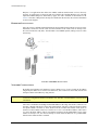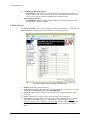
1
EX2500A
LXI-VXI GIGABIT ETHERNET
SLOT 0 INTERFACE
USER’S MANUAL
P/N: 82-0115-000
Released May 27, 2010
VTI Instruments Corp.
2031 Main Street
Irvine, CA 92614-6509
(949) 955-1894
VTI Instruments Corp.
TABLE OF CONTENTS
INTRODUCTION
Certification .......................................................................................................................................................... 5
Warranty ............................................................................................................................................................... 5
Limitation of Warranty ......................................................................................................................................... 5
Restricted Rights Legend ...................................................................................................................................... 5
DECLARATION OF CONFORMITY ............................................................................................................................... 6
GENERAL SAFETY INSTRUCTIONS ............................................................................................................................. 7
Terms and Symbols .............................................................................................................................................. 7
Warnings............................................................................................................................................................... 8
SUPPORT RESOURCES ............................................................................................................................................... 9
SECTION 1 .................................................................................................................................................................. 11
OVERVIEW .............................................................................................................................................................. 11
Overview ............................................................................................................................................................ 11
Features............................................................................................................................................................... 11
The Power of LXI ......................................................................................................................................... 11
Data Transfer Rates ....................................................................................................................................... 11
Simplified Cabling and Connectivity ............................................................................................................ 11
Familiar Software Interfaces ......................................................................................................................... 12
Embedded Resource Manager ....................................................................................................................... 12
Additional Features ....................................................................................................................................... 12
EX2500A Specifications .................................................................................................................................... 13
TCXO/OCXO Option Specifications ................................................................................................................. 14
SECTION 2 .................................................................................................................................................................. 15
PREPARATION FOR USE........................................................................................................................................... 15
Overview ............................................................................................................................................................ 15
Unpacking........................................................................................................................................................... 15
Required Equipment ........................................................................................................................................... 15
Software Installation ........................................................................................................................................... 15
Hardware Installation.......................................................................................................................................... 16
Network Configuration ....................................................................................................................................... 16
Cabling Considerations ....................................................................................................................................... 17
Segment Distance/Security............................................................................................................................ 17
EMI Environment .......................................................................................................................................... 18
Current LAN Implementation ....................................................................................................................... 18
Fiber Vs. Copper................................................................................................................................................. 18
Copper Cable Recommendation .................................................................................................................... 18
Fiber Optic Cable Recommendation ............................................................................................................. 18
Multiple Mainframe Configurations ................................................................................................................... 19
SECTION 3 .................................................................................................................................................................. 21
MODULE DESCRIPTION ........................................................................................................................................... 21
Front Panel Details ............................................................................................................................................. 21
LEDs ............................................................................................................................................................. 21
Connectors..................................................................................................................................................... 22
VXI RST / LAN RST Button ........................................................................................................................ 22
Gigabit Ethernet Functionality............................................................................................................................ 22
Power On Self-Test LED Error Codes................................................................................................................ 23
Top Cover Details ............................................................................................................................................... 23
User Configurable Switches .......................................................................................................................... 24
2
EX2500A Preface
www.vtiinstruments.com
SECTION 4 .................................................................................................................................................................. 25
SOFTWARE INSTALLATION...................................................................................................................................... 25
Introduction ........................................................................................................................................................ 25
VISA Requirements ............................................................................................................................................ 25
Agilent VISA as Primary VISA Installation Path ......................................................................................... 25
Agilent VISA as Secondary VISA Installation Path ..................................................................................... 25
AGILENT VISA AS PRIMARY VISA ........................................................................................................................ 26
VISA Installation ................................................................................................................................................ 26
EX2500A Driver Installation .............................................................................................................................. 30
VXI Plug&Play Driver .................................................................................................................................. 30
IVI Driver ...................................................................................................................................................... 32
Add the EX2500A Interface to Agilent VISA .................................................................................................... 34
AGILENT VISA AS SECONDARY VISA ................................................................................................................... 39
VISA Installation ................................................................................................................................................ 39
EX2500A Driver Installation .............................................................................................................................. 43
VXI Plug&Play Driver .................................................................................................................................. 43
IVI Driver ...................................................................................................................................................... 45
Configure NI-VISA for Use with Agilent VISA ................................................................................................ 47
Add the EX2500A Interface to Agilent VISA .................................................................................................... 48
SECTION 5 .................................................................................................................................................................. 53
WEB PAGE OPERATION........................................................................................................................................... 53
Opening the Web Page ....................................................................................................................................... 53
General Web Page Operation ............................................................................................................................. 53
Login Error Message ..................................................................................................................................... 54
Login ............................................................................................................................................................. 54
Firmware Version ............................................................................................................................................... 55
IP Configuration ................................................................................................................................................. 56
Module Options .................................................................................................................................................. 57
Time .................................................................................................................................................................... 58
LXI Synchronization .......................................................................................................................................... 59
LXI LAN Events ................................................................................................................................................ 60
LAN Event Log .................................................................................................................................................. 61
Device Status ...................................................................................................................................................... 62
Module Information ............................................................................................................................................ 63
Memory I/O ................................................................................................................................................... 64
Formatted I/O ................................................................................................................................................ 65
Resource Manager Control ................................................................................................................................. 66
Trigger Configuration ......................................................................................................................................... 67
Interrupt Control ................................................................................................................................................. 70
LED Test ............................................................................................................................................................ 71
Firmware Upgrade .............................................................................................................................................. 72
Report a Bug ....................................................................................................................................................... 73
SECTION 6 .................................................................................................................................................................. 75
TRIGGER MECHANISMS .......................................................................................................................................... 75
Overview ............................................................................................................................................................ 75
LXI Trigger Controls .......................................................................................................................................... 76
VXI Trigger Controls ......................................................................................................................................... 76
VXI Legacy ................................................................................................................................................... 77
LAN Event Trigger Controls .............................................................................................................................. 77
LXI Trigger Bus ................................................................................................................................................. 78
IEEE 1588 .......................................................................................................................................................... 78
EX2500A Preface
3
VTI Instruments Corp.
SECTION 7 .................................................................................................................................................................. 79
FIRMWARE UPDATES .............................................................................................................................................. 79
Updating EX2500A Firmware ............................................................................................................................ 79
SECTION 8 .................................................................................................................................................................. 81
TROUBLESHOOTING ................................................................................................................................................ 81
LED Error Codes ................................................................................................................................................ 81
Network Troubleshooting ................................................................................................................................... 82
Restore the EX2500A’s Default Network Settings ....................................................................................... 82
Determine PCs Network Settings .................................................................................................................. 82
Set the EX2500A to Auto IP ......................................................................................................................... 83
Set theEX2500A to Static IP ......................................................................................................................... 84
Restore the Host PCs Network Settings ........................................................................................................ 85
Using Multiple Network Cards ........................................................................................................................... 85
APPENDIX A............................................................................................................................................................... 89
GLOSSARY .............................................................................................................................................................. 89
INDEX ......................................................................................................................................................................... 91
4
EX2500A Preface
www.vtiinstruments.com
CERTIFICATION
VTI Instruments Corp. (VTI) certifies that this product met its published specifications at the time of shipment from
the factory. VTI further certifies that its calibration measurements are traceable to the United States National
Institute of Standards and Technology (formerly National Bureau of Standards), to the extent allowed by that
organization’s calibration facility, and to the calibration facilities of other International Standards Organization
members.
WARRANTY
The product referred to herein is warranted against defects in material and workmanship for a period of three years
from the receipt date of the product at customer’s facility. The sole and exclusive remedy for breach of any warranty
concerning these goods shall be repair or replacement of defective parts, or a refund of the purchase price, to be
determined at the option of VTI.
For warranty service or repair, this product must be returned to a VTI Instruments authorized service center. The
product shall be shipped prepaid to VTI and VTI shall prepay all returns of the product to the buyer. However, the
buyer shall pay all shipping charges, duties, and taxes for products returned to VTI from another country.
VTI warrants that its software and firmware designated by VTI for use with a product will execute its programming
when properly installed on that product. VTI does not however warrant that the operation of the product, or
software, or firmware will be uninterrupted or error free.
LIMITATION OF WARRANTY
The warranty shall not apply to defects resulting from improper or inadequate maintenance by the buyer, buyersupplied products or interfacing, unauthorized modification or misuse, operation outside the environmental
specifications for the product, or improper site preparation or maintenance.
VTI Instruments Corp. shall not be liable for injury to property other than the goods themselves. Other than the
limited warranty stated above, VTI Instruments Corp. makes no other warranties, express or implied, with respect to
the quality of product beyond the description of the goods on the face of the contract. VTI specifically disclaims the
implied warranties of merchantability and fitness for a particular purpose.
RESTRICTED RIGHTS LEGEND
Use, duplication, or disclosure by the Government is subject to restrictions as set forth in subdivision (b)(3)(ii) of the
Rights in Technical Data and Computer Software clause in DFARS 252.227-7013.
VTI Instruments Corp.
2031 Main Street
Irvine, CA 92614-6509 U.S.A.
EX2500A Preface
5
VTI Instruments Corp.
DECLARATION OF CONFORMITY
Declaration of Conformity According to ISO/IEC Guide 22 and EN 45014
MANUFACTURER’S NAME
VTI Instruments Corp.
MANUFACTURER’S ADDRESS
2031 Main Street
Irvine, California 92614-6509
PRODUCT NAME
LXI-VXI Slot 0 Interface
MODEL NUMBER(S)
EX2500A
PRODUCT OPTIONS
All
PRODUCT CONFIGURATIONS
All
VTI Instruments Corp. declares that the aforementioned product conforms to the requirements of
the Low Voltage Directive 73/23/EEC and the EMC Directive 89/366/EEC (inclusive 93/68/EEC)
and carries the “CE” mark accordingly. The product has been designed and manufactured
according to the following specifications:
SAFETY
EN 61010-1:2001 (2nd Edition)
EMC
EN 61326:1997 (w/A 1:1998 and A 2:2001) Class A
CISPR 22 (1997) Class A
VCCI (April 2000) Class A
ICES-003 Class A (ANSI C63.4 1992)
AS/NZS 3548 (w/A1 & A2:97) Class A
FCC Part 15 Subpart B Class A
I hereby declare that the aforementioned product has been designed to be in compliance with the relevant sections
of the specifications listed above as well as complying with all essential requirements of the Low Voltage Directive.
July 2008
Steve Mauga, QA Manager
6
EX2500A Preface
www.vtiinstruments.com
GENERAL SAFETY INSTRUCTIONS
Review the following safety precautions to avoid bodily injury and/or damage to the product.
These precautions must be observed during all phases of operation or service of this product.
Failure to comply with these precautions, or with specific warnings elsewhere in this manual,
violates safety standards of design, manufacture, and intended use of the product.
Service should only be performed by qualified personnel.
TERMS AND SYMBOLS
These terms may appear in this manual:
WARNING
Indicates that a procedure or condition may cause bodily injury or death.
CAUTION
Indicates that a procedure or condition could possibly cause damage to
equipment or loss of data.
These symbols may appear on the product:
ATTENTION - Important safety instructions
Frame or chassis ground
Indicates that the product was manufactured after August 13, 2005. This mark is
placed in accordance with EN 50419, Marking of electrical and electronic
equipment in accordance with Article 11(2) of Directive 2002/96/EC (WEEE).
End-of-life product can be returned to VTI by obtaining an RMA number. Fees
for take-back and recycling will apply if not prohibited by national law.
EX2500A Preface
7
VTI Instruments Corp.
WARNINGS
Follow these precautions to avoid injury or damage to the product:
Connect Cables Properly
To avoid damage and potential loss of phone service, ensure that
the RJ-45 connector on the front panel of the EX2500A is not
connected to a standard telephone jack. This should only be
connected to a network interface card, network router, or network
hub.
Avoid Electric Shock
To avoid electric shock or fire hazard, do not operate this product
with the covers removed. Do not connect or disconnect any cable,
probes, test leads, etc. while they are connected to a voltage source.
Remove all power and unplug unit before performing any service.
Service should only be performed by qualified personnel.
Ground the Product
This product is grounded through the grounding conductor of the
power cord. To avoid electric shock, the grounding conductor must
be connected to earth ground.
Operating Conditions
To avoid injury, electric shock or fire hazard:
Do not operate in wet or damp conditions.
Do not operate in an explosive atmosphere.
Operate or store only in specified temperature range.
Provide proper clearance for product ventilation to prevent
overheating.
DO NOT operate if any damage to this product is suspected.
Product should be inspected or serviced only by qualified
personnel.
Class 1 Laser Product
The SFP module in this instrument is a Class 1 Laser device. Do not
attempt to disassemble this module. In the interest of safety, this
equipment should only be serviced by an authorized
VTI Instruments representative. Please observe the following safety
precautions:
• Do not open the unit
• If the unit requires service, contact VTI Instruments
• Ensure proper use by reading and following the
instructions carefully
• Do not attempt to make any adjustments to the unit
Improper Use
8
The operator of this instrument is advised that if the equipment is
used in a manner not specified in this manual, the protection
provided by the equipment may be impaired.
Conformity is checked by inspection.
EX2500A Preface
www.vtiinstruments.com
SUPPORT RESOURCES
Support resources for this product are available on the Internet and at VTI Instruments customer
support centers.
VTI Instruments Corp.
World Headquarters
VTI Instruments Corp.
2031 Main Street
Irvine, CA 92614-6509
Phone: (949) 955-1894
Fax: (949) 955-3041
VTI Instruments
Cleveland Instrument Division
5425 Warner Road
Suite 13
Valley View, OH 44125
Phone: (216) 447-8950
Fax: (216) 447-8951
VTI Instruments
Lake Stevens Instrument Division
3216 Wetmore Avenue, Suite 1
Everett, WA 98201
Phone: (949) 955-1894
Fax: (949) 955-3041
VTI Instruments, Pvt. Ltd.
Bangalore Instrument Division
642, 80 Feet Road
Koramangala IV Block
Bangalore – 560 034
India
Phone: +91 80 4040 7900
Phone: +91 80 4162 0200
Fax: +91 80 4170 0200
Technical Support
Phone: (949) 955-1894
Fax: (949) 955-3041
E-mail: [email protected]
Visit http://www.vtiinstruments.com for worldwide support sites and service plan information.
EX2500A Preface
9
www.vtiinstruments.com
SECTION 1
OVERVIEW
OVERVIEW
VTI Instruments’ EX2500A is the industry’s first gigabit, LAN-based, VXI Slot 0 interface, which
merges Ethernet’s robust architecture and widespread infrastructure, the fast emerging LXI
standard for instrumentation, and the popular VXIbus platform. Providing a solution that
recognizes a system designer’s need to remain compatible with legacy systems and desire to adopt
new technologies, the EX2500A integrates key features of the LXI standard to create a versatile
interface that extends the VXIbus to an external host through the power of Ethernet.
FEATURES
The Power of LXI
The VXI TTL trigger bus is a powerful component of VXI-based systems and is used to facilitate
hardware handshaking between modules, freeing up the CPU for other tasks. With the introduction
of the EX2500A, all eight of the VXI TTL trigger lines can now be extended across multiple
mainframes and to other LXI devices through the LXI Trigger Bus compliant front panel
connectors (Low-Voltage Differential Signal or LVDS). Additionally, the EX2500A incorporates
the LXI standard VXI-11 instrument discovery mechanism, greatly simplifying integration within
hybrid systems.
Data Transfer Rates
As technology moves toward more data-intensive applications in the functional test and data
acquisition environments, the ability to quickly offload data to the host controller for processing is
critical. The EX2500A is a high-speed gigabit serial communications device and has been
optimized for transferring blocks of data in excess of 40 MB/s. A high-performance DMA
controller is used during block moves to achieve superior transfer rates. This is accomplished
without compromising traditional message-based (word-serial) command performance.
Simplified Cabling and Connectivity
Communication back to the host processor is achieved using a standard Cat 5e Ethernet cable.
Distances up to 200 meters between mainframe and host can be realized. A fiber optic connection
is available if even greater distances are required. Wireless control of VXI instruments is also now
possible through the use of wireless routers. The EX2500A achieves top performance when
connected to a gigabit LAN interface which is also a standard item in recent PC motherboards.
Low-cost gigabit Ethernet switches can be used to connect multiple mainframes to a single host.
For legacy systems, SMB connectors are provided for single-line trigger input/output as well as
external reference clock input/output.
EX2500A Introduction
11
VTI Instruments Corp.
Familiar Software Interfaces
The EX2500A is fully compliant with the VXIplug&play specifications and implements VISA as
the API communication layer. A standard VISA I/O library is included and integrates seamlessly
with either Agilent Technologies™ or National Instruments™ versions of VISA. This greatly
simplifies installation of the EX2500A into legacy systems using the VISA protocol and preserves
any investment in existing TPS (Test Program Set) and driver development by eliminating the
need for costly code modifications.
The VXI Resource Manager is resident on the module and executed automatically at power up, all
system resources are allocated without the need to run a separate utility. The EX2500A runs an
embedded web interface and system status including installed VXI hardware, memory allocation,
IP configuration, and logical address information can be viewed through an LXI-compliant web
page. Direct communication to installed devices through message or register-based commands can
be achieved through this interface. This interface allows firmware updates to be accomplished
quickly and easily.
Embedded Resource Manager
A resource manager (RESMAN), as defined by the VXIbus specification, primarily performs the
task of identifying all VXI devices in a mainframe and ensures that these devices have passed their
self-tests. RESMAN also configures the system’s A24 and A32 address maps, allocates the
VMEbus interrupt lines, and initiates normal system operation. Furthermore, RESMAN
establishes a system wide control hierarchy described by Commander and Servant relationships.
Unlike other Slot 0 interfaces, the EX2500A has an embedded resource manager that runs on
every power up. Because RESMAN is integrated into the EX2500A, there is no need for this
utility to be available in any other location, such as a PC. Since RESMAN runs on every power
cycle of the EX2500A, user’s free themselves form the need to run this application manually as
well as the need to remember to run the application after device changes have been made to the
mainframe.
Additional Features
The following features are also available on the EX2500A:
•
•
•
•
•
•
•
•
•
•
12
Dual media gigabit Ethernet interface (Cat 5e UTP or SFP-1000BASE SX or LX fiber optic).
Auto-MDIX (Medium Dependent Interface Crossover) operation, eliminating the need for
crossover cables.
Detailed link status indicators for Ethernet interface.
Sophisticated trigger routing capabilities between the front panel input connectors (clock and
trigger), LXI triggers, VXI triggers, and LXI LAN Events.
Integrated web interface to provide status, test, and software/firmware update capability.
Options for TCXO or OCXO Clock 10 generation.
256 MB of 333 MHz DDR system memory, upgradeable to 2 GB.
Capable of VXI-3.0 2eVME backplane cycles.
LXI 1588 operation.
A16, A24, and A32 address space access.
EX2500A Introduction
www.vtiinstruments.com
EX2500A SPECIFICATIONS
GENERAL SPECIFICATIONS
PHYSICAL ATTRIBUTES
Size
Weight
SLOT 0 CAPABILITY
1-slot, C-size
2.5 lbs (1.1 kg)
Yes
RESOURCE MANAGER
Embedded
ADDRESS SPACE ACCESS
A16, A24, and A32
VXI REVISION COMPLIANCE
1.4, 2.0, 3.0
LXI REVISION COMPLIANCE
LXI 1.0 Class A
MAXIMUM DATA TRANSFER RATE (BLOCK MOVE)
40 MB/s
MEMORY (DRAM)
256 MB, 333 MHz DDR SDRAM
Standard
Up to 2 GB available
Optional
TRIGGER SUPPORT
VXI TTL 0 - 7, LXI 0 - 7, LAN Events, VXI ECL 0 - 1, and the VXI 10 MHz clock
Bus Lines
EXT TRIG IN, EXT TRIG OUT
Front Panel Connectors
PROCESSOR SPEED
825 MHz
ETHERNET PROTOCOL
TCP/IP, VXI-11
I/O LIBRARY
Agilent I/O Library Suite (14.2 or later)
VISA SUPPORT
VXIplug&play compliant
OPERATING SYSTEM SUPPORT
Windows XP, Windows 2000
LXI REQUIRED SPECIFICATIONS
TRIGGER-TO-TRIGGER RESPONSE TIMES
External Trigger→ LXI Trigger Bus Channel
External Trigger → VME TTL or ECL
LXI Trigger Bus Channel → External Trigger
LXI Trigger Bus Channel → VME TTL or ECL
LXI Trigger Bus Channel → LXI Trigger Bus Channel
VME TTL or ECL → External Trigger
VME TTL or ECL → LXI Trigger Bus Channel
VME TTL or ECL → VME TTL or ECL
TIMESTAMP ACCURACY
Typical
22 ns
30 ns
22 ns
22 ns
20 ns
20 ns
20 ns
22 ns
1 ms
BACKPLANE POWER REQUIREMENTS
VOLTAGE
IPEAK
IDYNAMIC
ENVIRONMENTAL
OPERATING TEMPERATURE
+5 V
4.6 A
450 mA
+12 V
45 mA
1 mA
+24 V
0 mA
0 mA
-2 V
55 mA
4 mA
-5.2 V
150 mA
2 mA
-12 V
0 mA
0 mA
-24 V
0 mA
0 mA
+5 V STBY
0 mA
0 mA
0 °C to +50 °C
HUMIDITY
5% to 85% relative humidity
EX2500A Introduction
13
VTI Instruments Corp.
TCXO/OCXO OPTION SPECIFICATIONS
STANDARD OSCILLATOR – USE VXI 10 MHZ
PERFORMANCE
±50 ppm
TCXO OPTION
PERFORMANCE
High Performance
AGING
±1 x 10⁻⁶/year
TEMPERATURE
±3 x 10⁻⁶ (0 °C to 50 °C)
ADJUSTMENT RANGE
±3 x 10⁻⁶ min
WARM-UP TIME
N/A
OCXO OPTION
PERFORMANCE
Ultra High Performance
AGING
±1 x 10⁻⁷/year
TEMPERATURE
Less than ±2 x 10⁻⁸ (0 °C to 70 °C)
ADJUSTMENT RANGE
±4 x 10⁻⁷ min
WARM-UP TIME
< 3 minutes
14
EX2500A Introduction
www.vtiinstruments.com
SECTION 2
PREPARATION FOR USE
OVERVIEW
This section provides a step-by-step process for setting up the EX2500A for use. It covers
hardware installation, input connections, and cabling considerations.
UNPACKING
When the EX2500A is unpacked from its shipping carton, the contents should include the
following items:
•
•
•
•
•
•
EX2500A LXI-VXI Gigabit Ethernet Slot 0 Interface
LXI Quick Start Guide
EX2500A User’s Manual (this manual)
EX2500A Quick Start Guide
VTI Instruments Corp. Drivers and Product Manuals CD
Agilent IO Library distribution CD
All components should be inspected for damage. Also, take note of the MAC address located in
the Card Configuration section of the product label found on the top side cover (see Figure 3-2).
The MAC address may be required if problems arise when locating the module in the local
network.
REQUIRED EQUIPMENT
In order to use the EX2500A, the following items are required:
•
•
•
•
A VXIbus mainframe
One of the following network cables:
o Unshielded Category 5e (Cat 5e) Ethernet cable not exceeding 100 m in length.
o Fiber optic cable with appropriate connector for SFP module used (typically LC style
connectors) not to exceed the SFP manufacturers maximum length specification.
A gigabit Ethernet switch (if multiple devices will be connected on the network).
VMIP, SMIP, or other VXIbus cards which are part of the test system.
SOFTWARE INSTALLATION
The fastest way to begin controlling an EX2500A is to discover the unit using Bonjour™. To do
this, the following software must be installed on the host PC:
•
•
•
An Internet connection
A Microsoft™ Windows™ XP OS with Service Pack 2 (SP2) and Internet Explorer™ (IE)
Bonjour for Windows version 1.0.4 (or later)
EX2500A Preparation for Use
15
VTI Instruments Corp.
Bonjour is an application that utilizes the mDNS (multicast domain name service) discovery
protocol. As an IE plug-in, it allows the end user to identify all compliant hardware on a LAN that
implement mDNS. Bonjour is distributed by Apple, Inc. and is available for download over the
Internet. Note that, if Bonjour has already been installed on the host PC, this software installation
section can be skipped.
HARDWARE INSTALLATION
Once the system is defined and the EX2500A has been installed in the leftmost slot (slot 0) of the
mainframe, connect the network cable from the EX2500A to the LAN switch or directly to the
PCs network interface card (NIC). The EX2500A is auto-MDIX capable, making crossover cables
unnecessary.
FIGURE 2-1: EX2500A INSTALLATION
NETWORK CONFIGURATION
By default, the EX2500A will attempt to locate a DHCP server. If one is found, the IP address
assigned by the DHCP server will be used. Otherwise, after a timeout of 20 seconds, the unit will
attempt to obtain an IP address by using Auto IP.
NOTE
At any time, the EX2500A can be returned to a known, default network configuration by using the
LCI (LAN Configuration Initialize) mechanism. See VXI RST / LAN RST Button section for more
information.
Auto IP is a mechanism for finding an unused IP address in the range 169.254.X.Y, where X is in
the range 1 through 254 and Y is in the range 0 through 255. The device will first attempt to obtain
the specific address 169.254.X.Y, where X and Y are the second-to-last and last octets (bytes) of
the device’s MAC address. However, X will be set to 1 if it is 0 in the MAC address, and to 254 if
it is 255 in the MAC address. This is in accordance with the Auto IP standard (RFC 3927). If this
address is already in use, the unit will attempt to obtain other IP addresses in a pseudorandom
fashion until it finds one that is available.
16
EX2500A Preparation for Use
www.vtiinstruments.com
To illustrate the Auto IP mechanism, Table 2-1 lists the Auto IP default address for some example
MAC addresses.
MAC Address
00:0D:3F:01:00:01
00:0D:3F:01:01:01
00:0D:3F:01:A3:28
00:0D:3F:01:FE:FE
00:0D:3F:01:FF:FE
Auto IP Default Address
169.254.1.1
169.254.1.1
169.254.163.40
169.254.254.254
169.254.254.254
TABLE 2-1: AUTO IP DEFAULT ADDRESS ASSIGNMENT
If a static IP address assignment is preferred, one can be optionally assigned via the embedded
web page interface. This is done by clicking the Network Configuration link, disabling DHCP
and Auto IP, enabling Static, and then assigning a static IP address, subnet mask, and gateway
address, and, optionally up to three DNS servers. For more information, see IP Configuration in
Section 5.
NOTE
The 169.254/16 subnet is reserved by the IANA for Auto IP usage. It should not be used for either
DHCP or static IP configurations.
However, a much more convenient and recommended way to obtain the benefits of a static IP
address is to employ DHCP, but assign the instrument a reserved IP address in your company’s
DHCP server configuration. This reserved address, linked to the EX2500A’s MAC address on the
DHCP server, would be assigned to the EX2500A at power up initialization without having to
manually set it on the EX2500A. The DHCP server configuration provides a centralized,
controlled database of assigned IP addresses, preventing accidental assignment of the same IP
address to multiple instruments. Consult your company’s Information Technology department for
assistance.
VXI-11 Device Discovery is also supported by the EX2500A. This allows all EX2500s on a local
network to be found without knowledge of their MAC address or IP address with the use of a
broadcast message.
If problems occur when trying to connect to the EX2500A, see Network Troubleshooting in
Section 8 for assistance.
CABLING CONSIDERATIONS
The EX2500A can interface with a network through either copper or fiber media. Copper media
allows for three communication speeds: 10/100/1000 Mb/s, whereas fiber media is a 1000 Mb/s
only interface. To determine which type of media to use, some general guidelines can be made.
Segment Distance/Security
10/100/1000BASE-TX network spans are limited to 200 meters (100 meters point-to-point) and,
therefore, the developers of larger LANs face the necessity of providing fiber optic connectivity.
In general, fiber is reserved for situations that require cabling distances greater than 200 meters.
For example, going between buildings in a corporate campus environment or connecting
departments located on different floors of a high rise building.
Security is another possible factor that could influence a user to utilize fiber cabling. Fiber optic
cable cannot be spliced except under clean room conditions, making it nearly impossible for a
hacker to tap into the cable. A situation that requires an exposed intra-building network connection
makes fiber the best choice.
EX2500A Preparation for Use
17
VTI Instruments Corp.
EMI Environment
Copper cable is susceptible to electromagnetic interference, which can corrupt files or generate
additional Ethernet traffic in the form of reissued messages. Fiber cable is not susceptible to these
electromagnetic sources of interference. Using fiber optic cabling with the EX2500A allows for
control of a test chassis from a computer located far away from the test lab or in areas that are near
elevators, fluorescent lighting, or other sources of high external noise.
Current LAN Implementation
If the potential location of an EX2500A is on an existing 10/100 Mb/s network, a gigabit fiber
connection will not fit without additional network equipment. At a minimum, a switch with a
gigabit fiber port is needed to connect fiber to the EX2500A. On the other hand, another Cat 5e
UTP patch cord would be the only requirement to put the EX2500A on the existing network.
FIBER VS. COPPER
The table below summarizes some of the differences between fiber optic and copper cabling:
FIBER
Gigabit
40 km+ @ 1,000 Mb/s
Immune
Almost impossible to tap
Bandwidth
Distance
Noise
Security
COPPER
Gigabit
100 m @ 1000 Mb/s
EMI/RFI susceptible
Susceptible to tapping
TABLE 2-2: CABLE COMPARISON
Copper Cable Recommendation
The type of copper cable VTI recommends is Cat 5e UTP (Unshielded Twisted Pair).
Fiber Optic Cable Recommendation
Fiber optic cables are specified by their core diameter and the type of fiber: multi-mode or singlemode. When using a 1000BASE-SX fiber optic transceiver, three possible cable choices can be
made:
1) 62.5/125 μm MMF(multi-mode fiber)
2) 50/125 μm MMF
3) 9/125 µm SMF (single-mode fiber)
In the descriptions above, the first number refers to the diameter of the fiber optic core, and the
second number refers to the diameter of the cladding. The cladding is the outer diameter and the
core refers to the cable’s inner diameter. (See Figure 2-2 below.)
Cable Jacket
Cladding
Core
FIGURE 2-2: FIBER OPTIC CABLE CROSS-SECTION
18
EX2500A Preparation for Use
www.vtiinstruments.com
In general, the core diameter is segment length dependent. If the fiber segment between the
EX2500A and the switch is 2 m to 300 m, use a 62.5/125 μm MMF cable. For segments greater
than 300 m, use a 50/125 μm MMF cable. Finally, the proper fiber cable connectors must be
specified when ordering X/125 μm MMF cable. The EX2500A interfaces to fiber via the SFP port.
This port accepts a transceiver that requires an LC duplex style connector. The other end that
connects to the switch must be specified by the user.
MULTIPLE MAINFRAME CONFIGURATIONS
The EX2500A features an 8-channel LXI trigger bus on the front panel. These channels are used
primarily for high-speed multi-unit triggering and synchronization. Currently, the EX2500A can
route VME TTL or ECL triggers to the LXI trigger bus or from the LXI trigger bus to the VME
aforementioned triggers. Connecting the EX2500A’s LXI trigger bus to other LXI devices or to
other EX2500As is done using a VTI Instruments trigger bus cable.
EX2500A Preparation for Use
19
VTI Instruments Corp.
20
EX2500A Preparation for Use
www.vtiinstruments.com
SECTION 3
MODULE DESCRIPTION
FRONT PANEL DETAILS
This section details each element found on the EX2500A front panel and describes the intended
use of these elements. See Figure 3-1 below as a reference while the EX2500A front panel is
discussed.
LEDs
•
•
•
•
•
•
VXI ACC: the VXI access indicator, this LED will blink green for backplane accesses that
terminate properly. It will blink orange for accesses that terminate in retry or bus error.
SYSFAIL: indicates EX2500A SYSFAIL status (does not indicate backplane SYSFAIL
status). Note that the center LED is not used by the EX2500A.
PWR: indicates that the power supply voltages lines are at the correct voltage. This LED will
temporarily glow red when the EX2500A is initially powered up and when the VXI/LAN
RST button is pushed.
LAN: indicates the LAN status of the EX2500A.
o A solid green LAN LED indicates normal operation.
o A flashing green, LAN LED indicates that the EX2500A has received a device
identification command. The LAN LED will continue to flash until it is turned off via the
web page.
o A solid red LAN LED indicates that a LAN fault has been detected. This may be a failure
to acquire a valid IP address, to renew a DHCP IP lease, detection of a duplicate IP
address, or that the LAN cable has been disconnected.
1588: indicates the EX2500A’s IEEE 1588 synchronization status.
o A solid green 1588 LED indicates that the EX2500A’s device clock is an IEEE 1588
slave.
o A 1588 LED flashing green once per second indicates that its clock is the IEEE 1588
master.
o A 1588 LED flashing green once every two seconds indicates that the EX2500 is the
IEEE 1588 grandmaster.
o If the LED is solid red, an IEEE 1588 fault has occurred. If this LED is not illuminated, it
the EX2500A is not synchronized with the IEEE 1588 clock.
Ethernet Link Status Indicators
o A/B/C: provides link status for the established “GIGABIT ETHERNET” connection and
indicates the following:
bus
FIGURE 3-1:
EX2500A FRONT
PANEL
EX2500A Module Description
LED A
OFF
ON
OFF
OFF
ON
OFF
LED B
ON
OFF
OFF
ON
OFF
OFF
LED C
ON
ON
ON
OFF
OFF
OFF
Mode
1000 Mb/s Fiber, Link-up
1000 Mb/s Cat 5 Master, Link-up
1000 Mb/s Cat 5 Slave, Link-up
100 Mb/s Cat 5, Link-up
10 Mb/s Cat 5, Link-up
Link Down
21
VTI Instruments Corp.
NOTE
o
Ensure that LED control is returned to “Normal” when exiting the LED test or Device
Identification section of the web interface.
Tx/Rx/DUPLEX: provides transmit (Tx), receive (Rx), and duplex status for the
established “GIGABIT ETHERNET” connection. When the “DUPLEX” LED is
illuminated, this indicates that a full-duplex connection has been established. A halfduplex connection is indicated otherwise.
Connectors
•
•
•
•
•
CLK IN/OUT: SMB connectors that provide external clocking options for the EX2500A.
SFP FIBER OPTIC: a fiber optic gigabit Ethernet connector that accommodates an SX or
LX Small Form Factor Pluggable (SFP) module.
CAT5e: an RJ-45 connector that accommodates Category 5e (Cat 5e) twisted pair.
LXI TRIGGER BUS: an 8-channel LXI-compliant trigger mechanism that can be used to
route all VXI TTL triggers rack-to-rack or rack-to-LXI module.
TRIG IN/OUT: SMB connectors used to route VXI TTL triggers and trigger bus signals.
VXI RST / LAN RST Button
LXI LAN Configuration Initialize (LCI) Mechanism
The VXI RST / LAN RST button, implemented according to the LXI LAN Configuration
Initialize (LCI) Mechanism specification, on the EX2500A front panel provides a mechanism for
recovery from an unknown or incorrect network configuration. If, for example, the EX2500A was
statically configured for test or demonstration purposes and was not returned to “DHCP/AUTO
IP” mode, the module may not be found by the original network setup. Following the procedure
below will place the EX2500A’s IP configuration mode into “DHCP/AUTO IP” as well as
ensuring that mDNS discovery is enabled:
1) Press and hold the reset button until the LXI PWR LED changes from red to green
(approximately 5 s).
2) Release the reset button.
NOTE
Resetting the EX2500A will also reset the web page interface password to “ex2500”.
VXI-11 Device Discovery (supported by the VISA IO-Libraries) is also supported by the
EX2500A. This allows all EX2500A on a local network to be found without knowledge of their
MAC address or IP address with the use of a broadcast message.
GIGABIT ETHERNET FUNCTIONALITY
The EX2500A automatically detects whether the twisted pair (RJ-45) or fiber optic (SFP)
connection is active and switches without user intervention. For Cat 5e connections, the EX2500A
provides auto-MDIX functionality that automatically handles crossover in point-to-point
connections. The unit will also detect and correct pairs that are wired backwards. Therefore,
crossover cables can be used, but are not required.
NOTE
22
If Cat 5e (RJ-45) and fiber (SFP) media are both connected at power up, the port that first achieves
link (typically the SFP) will be used. Also, if a link is established on one media type, and the other
media is connected, the established link is maintained.
EX2500A Module Description
www.vtiinstruments.com
POWER ON SELF-TEST LED ERROR CODES
The EX2500A runs a power on self-test (POST) whenever it is powered up or reset. If a POST
failure occurs, the link status LEDs on the front panel are used to display the error which has
occurred. The table below provides a description of the LEDs behavior during an error event.
LED
ERROR
RAM FAIL
RECOVERY OS NOT
BOOTABLE
BOOTLOADER
MEMORY TEST FAIL
PHY LOOPBACK FAIL
10 MHz FAIL
16 MHz FAIL
VME IRQ FAIL
CPLD IRQ FAIL
FPGA IRQ FAIL
A
BLINK
BLINK
B
OFF
BLINK
C
OFF
BLINK
Tx
BLINK
BLINK
Rx
OFF
BLINK
DUPLEX
BLINK
BLINK
ON
OFF
OFF
ON
OFF
BLINK
OFF
BLINK
OFF
ON
OFF
OFF
ON
OFF
OFF
OFF
ON
OFF
OFF
ON
ON
ON
ON
ON
OFF
OFF
BLINK
OFF
OFF
ON
ON
OFF
OFF
OFF
OFF
OFF
BLINK
BLINK
BLINK
BLINK
BLINK
BLINK
TABLE 3-1: LED ERROR CODES
TOP COVER DETAILS
From the top cover of the EX2500A, several switches can be viewed with various functions. These
switches must be configured prior to installation of the EX2500A into a mainframe. The default
setting for each of these switches is underlined in order to provide a quick reference when in the
field. The section that follows provides a detailed description for each configurable switch.
VXI Technology, Inc.
Model:
P/N:
S/N:
2031 Main St, Irvine, CA 92614
(949) 955-1894
Rev: A
Options:
70-0313-000
116372
None
GENERAL VXIbus INFORMATION
DEFAULT SWITCH
SETTINGS INDICATED
BY UNDERLINE
VXIbus Rev:
Device Type:
Addressable Memory
3.0
Message Based Commander
A16 A24 A32 Master
POWER/COOLING REQUIREMENTS
Voltage:
I Peak:
I Dynamic:
+5V
4.5A
450mA
Airflow:
Temparature:
Module Weight:
+12V
4.5mA
1mA
+24V
0mA
0mA
-2V
55mA
4mA
-5.2V
150mA
2mA
-12V
0mA
0mA
-24V
0mA
0mA
+5VSTBY
0mA
0mA
2.8 Liters/sec at 0.28mm H2O for a 10°C Internal Rise
55°C Maximum
2.5 Lbs
MAC Address: 00:0D:3F:01:02:73
CARD CONFIGURATION
MADE IN U.S.A.
CAUTION
SENSITIVE ELECTRONIC DEVICE
DO NOT SHIP OR STORE NEAR STRONG
ELECTROSTATIC, ELECTROMAGNETIC,
MAGNETIC OR RADIOACTIVE FIELDS
ELECTROSTATIC
SENSITIVE DEVICE
FIGURE 3-2: EX2500A TOP COVER
EX2500A Module Description
23
VTI Instruments Corp.
User Configurable Switches
•
CLK10 IN 50 OHM TERMINATION IN/OUT: when “IN” is selected, a 50 Ω impedance
to ground is presented to the incoming waveform. This is useful when connecting these ports
to 50 Ω BNC-to-SMB cables. When “OUT” is selected, the 50 Ω termination is removed.
The default for this switch is “OUT” (switch in the up position).
•
CLK10 OUT TURNED ON/OFF: when “ON” is selected, a 10 MHz clock signal is
available at EXT CLK OUT. When “OFF” is selected, the 10 MHz clock signal is not routed
to the SMB connector.
The default for this switch is “OFF” (switch in the up position).
•
CLK10 OUT (NOT) INTERTED: when “NOT INVERTED” is selected, the 10 MHz clock
signal on the CLK OUT port is in phase with the on-board oscillator. When “inverted”, the
10 MHz clock signal is 180° out-of-phase with the oscillator.
The default for this switch is “NOT INVERTED” (switch in the down position).
•
TRIG IN 50 OHM TERMINATION IN/OUT: when “IN” is selected, a 50 Ω termination is
presented to the incoming trigger signal. This is useful when connecting these ports to 50 Ω
BNC-to-SMB cables. When “OUT” is selected, the 50 Ω termination is removed.
The default for this switch is “OUT” (switch in the up position).
•
ON-BOARD OSCILLATOR TRIM DIS-CONNECTED/CONNECTED: when the
EX2500A is loaded with the TCXO or OCXO option, this switch enables the 10 MHz output
to be trimmed. When “connected” is selected, the clock trim is enabled for the TCXO/OCXO
options. The position of this switch is irrelevant with the standard oscillator option. When
“DIS-CONNECTED”, or in the up position, the TCXO/OCXO clock trim is disabled.
The default for this switch is “CONNECTED” (switch in the down position).
•
ON-BOARD OSCIALLATOR POWER ON/OFF: when “ON” is selected, the VXIbus
backplane CLK10 + and CLK10 – signals are enabled. This switch should be in the down
default position in most applications.
The default for this switch is “ON” (switch in the down position).
•
EXTERNAL/ON-BOARD OSCIALLATOR SELECTED: when “ON-BOARD” is
selected, the EX2500A’s on-board oscillator (CLK10, TCXO, or OCXO) is selected. When
“EXTERNAL” is selected, the front panel SMB CLK10 input signal is used for the VXIbus
backplane CLK10 + and CLK10 – signals.
The default for this switch is “IN” (switch in the down position).
24
EX2500A Module Description
www.vtiinstruments.com
SECTION 4
SOFTWARE INSTALLATION
INTRODUCTION
The EX2500A driver was written to be used with Agilent®VISA and, therefore, requires this
software to be installed to function properly. Two software installation paths should be considered
by users when installing the required EX2500A software:
•
•
NOTE
Use with Agilent VISA software, where Agilent VISA is installed as the primary VISA.
Use with existing National Instruments©VISA (NI-VISA) software, which requires Agilent
VISA to be installed as the secondary VISA and NI-VISA to be configured properly to
support Agilent VISA.
The screenshots provided in this section were captured on a Windows®XP® system using specific
VISA (Virtual Instrument Software Architecture) installations. As such, it is possible that the
images provided in this guide may not be identical to the images seen during a specific
installation.
VISA REQUIREMENTS
In order to work properly in a test system, the EX2500A requires Agilent VISA to be installed on
the host PC. Agilent VISA may be installed as either the primary VISA, or may be installed
secondary to NI-VISA. The EX2500A is compatible with the following VISA software revisions:
1) Agilent VISA Revision 14.2 or later
2) NI-VISA Revision 2.6 or later for guaranteed operation (VTI Instruments Corp., however,
recommends using revision 3.4 or later)
Agilent VISA as Primary VISA Installation Path
If Agilent VISA revision 14.2 or later is installed on the PC that will be connected to the
EX2500A, go to page 30. If a different version of Agilent VISA is installed on the host PC, go to
page 26 to install revision 14.2. It is recommended that previous versions of Agilent VISA be
removed before installing revision 14.2.
Agilent VISA as Secondary VISA Installation Path
If NI-VISA revision 2.6 or later is installed on the host PC, go to page 39. If the version of
NI-VISA installed on the host PC is lower than revision 2.6, please install an appropriate version
of NI-VISA and then go to page 39.
EX2500A Software Installation
25
VTI Instruments Corp.
AGILENT VISA AS PRIMARY VISA
VISA INSTALLATION
1) Start installation of Agilent VISA. From the Agilent IO Library Distribution CD, run the
program iolibs_suite_14_2_8931_1_multimedia.exe (or later). At the Welcome screen, click
the Next button.
2) At the License Agreement dialog box, click on the “I accept” radio button to accept the
license agreement, and then click Next to continue. If this is not done, installation will cease.
26
EX2500A Software Installation
www.vtiinstruments.com
3) At the Setup Type dialog box, select the Custom radio button, then click the Next button.
4) At the Install Agilent VISA dialog box, a prompt appears asking if Agilent VISA will be
installed as the primary VISA. Ensure that Install Agilent VISA as primary VISA is
selected, and then click the Next button.
EX2500A Software Installation
27
VTI Instruments Corp.
5) No changes are required at the Choose Destination Location dialog box. Click the Next
button to continue.
6) At the Select Features dialog box, a summary of features that will be installed is provided.
Make certain that the Agilent VISA as primary VISA check box is selected. Once this has
been verified, click the Next button to continue.
28
EX2500A Software Installation
www.vtiinstruments.com
7) Next, the Start Copying Files dialog box will appear. To begin software installation, click the
Install button.
8) Once Agilent VISA installation is complete, the InstallShield Wizard Complete dialog box
will appear. As the EX2500A driver must be installed before the Agilent Connection Expert
can be used, ensure that both check boxes on this dialog box are not selected. Click the Finish
button to complete VISA installation.
EX2500A Software Installation
29
VTI Instruments Corp.
EX2500A DRIVER INSTALLATION
VXI Plug&Play Driver
1) From the VTI Instruments Corp. Drivers and Product Manuals CD, run the program
Drvr_EX2500A_R2p1p0.msi (or later). At the Welcome dialog box, click the Next button.
2) From the Select Installation Folder dialog box, select an appropriate radio button according
to host PC demands. No changes are required in the Folder field. Click the Next button to
proceed.
30
EX2500A Software Installation
www.vtiinstruments.com
3) At the Confirm Installation dialog box, click the Next button.
4) Click the close button and continue to Add the EX2500A Interface to Agilent VISA.
EX2500A Software Installation
31
VTI Instruments Corp.
IVI Driver
1) From the VTI Instruments Corp. Drivers and Product Manuals CD, run the program
VTEX2500A_R2p0p0p0.msi (or later). At the Welcome dialog box, click the Next button.
2) At the End-User License Agreement dialog box, select the “I accept” radio button, then
click Next to continue.
32
EX2500A Software Installation
www.vtiinstruments.com
3) At the Choose Setup Type dialog box, select Typical, then click Next.
4) After selecting the Typical setup, click on the Install button to begin driver installation.
EX2500A Software Installation
33
VTI Instruments Corp.
5) Once installtion of the driver is complete, click the Finish button on the Completing Setup
dialog box.
ADD THE EX2500A INTERFACE TO AGILENT VISA
1) Open Agilent’s Connection Expert© from the Start Menu via the path Start > All Programs >
Agilent IO Libraries Suite > Agilent Connection Expert.
34
EX2500A Software Installation
www.vtiinstruments.com
2) From the Connection Expert main window, click the Add an interface link in the Task
Guide field.
3) From the Manually Add an Interface dialog box, select VTI Instruments LXI-VXI Slot 0
Interface from the list and then click Add.
4) A configuration window will appear where a module is assigned a VISA interface ID which is
then mapped to the device’s IP address. There must be a unique VISA interface ID for each
interface defined in a system. NOTE: If NI-VISA is installed and any MXI-2 devices may be
used, a VISA Interface ID other than VXI0 must be assigned to the EX2500A, as NI-VISA
reserves VXI0 for MXI-2 devices. To automatically search for the module, click on Search
Local Network on the configuration window. This software utility will search for EX2500As.
If the EX2500A is connected directly to the Network Interface Card (NIC) in the host system,
the EX2500A software will automatically assign a link-local IP address based on the MAC
address of the module. If the module is connected to a LAN that is DHCP enabled, the DHCP
server will assign an IP address to the module. To determine if a LAN is DHCP enabled,
please contact your Network Administrator.
EX2500A Software Installation
35
VTI Instruments Corp.
From here, the user can also choose to have connection errors added to the Windows Event
Log by clicking on the Log LAN connection errors checkbox. The user can also set a the
time Connection Expert will wait before timing out. This is done by entering a value in the
Connect timeout text field. It should be noted that the LAN maximum timeout and Client
delta timout fields are not currently supported by the EX2500A.
NOTE
On PCs running Windows XP, the Windows Firewall utility may try to block Connection
Expert from connecting to the EX2500A. To avoid blocking multiple connections, it may be
desirable to turn off Windows Firewall. Refer to Windows Help for more information.
5) Connection Expert will display the IP address of all EX2500As discovered on the network.
Clicking LEDs runs a test on the LEDs of the highlighted EX2500A causing the Link Status
LEDs to blink in a “leap-frog pattern”. An additional dialog box will appear asking if this is
the correct module. It this is the module of interest, click OK to establish the highlighted
EX2500A as the target module.
36
EX2500A Software Installation
www.vtiinstruments.com
The IP address field will now contain the IP of the target EX2500A. Clicking OK assigns the
VISA interface ID shown to the target EX2500A.
NOTE
This process should be repeated for each EX2500A included in a test system. It is imperative that
each EX2500A module have a unique VISA interface ID.
If a MXI-2 interface will be installed into a mainframe after an EX2500A has been installed, the
EX2500A should have its VISA interface ID reassigned if its ID is VXI0. If this is not done, it will
cause the I/O software to perform improperly and make accessing the EX2500A impossible.
EX2500A Software Installation
37
VTI Instruments Corp.
6) The Slot 0 interface to the EX2500A should now appear in the Instrument I/O on this PC
field. The adjacent field contains buttons that allow for EX2500A properties to be changed
and provide access to the built-in web interface.
The EX2500A soft front panel and other programs should now be accessible.
38
EX2500A Software Installation
www.vtiinstruments.com
AGILENT VISA AS SECONDARY VISA
VISA INSTALLATION
1) Start installation of Agilent VISA. From the Agilent IO Library Distribution CD, run the
program iolibs_suite_14_2_8931_1_multimedia.exe (or later). At the Welcome screen, click
the Next button.
2) At the License Agreement dialog box, click on the “I accept” radio button to accept the
license agreement, and then click Next to continue. If this is not done, installation will cease.
EX2500A Software Installation
39
VTI Instruments Corp.
3) At the Setup Type dialog box, select the Custom radio button, then click the Next button.
4) At the Install Agilent VISA dialog box, a prompt appears asking if Agilent VISA will be
installed as the primary VISA. Ensure that Install Agilent VISA as primary VISA is not
selected, and the click the Next button. The screenshot below is from a system with NI-VISA
already installed.
40
EX2500A Software Installation
www.vtiinstruments.com
5) No changes are required at the Choose Destination Location dialog box. Click the Next
button to continue.
6) At the Select Features dialog box, a summary of features that will be installed is provided.
Ensure that the Agilent VISA as primary VISA checkbox is not selected.
EX2500A Software Installation
41
VTI Instruments Corp.
7) Next, the Start Copying Files dialog box will appear. To begin software installation, click the
Install button.
8) Once Agilent VISA installation is complete, the InstallShield Wizard Complete dialog box
will appear. As the EX2500A driver must be installed before the Agilent Connection Expert
can be used, ensure that both check boxes on this dialog box are no selected. Click the Finish
button to complete VISA installation.
42
EX2500A Software Installation
www.vtiinstruments.com
EX2500A DRIVER INSTALLATION
VXI Plug&Play Driver
1) From the VTI Instruments Corp. Drivers and Product Manuals CD, run the program
Drvr_EX2500A_R2p1p0.msi (or later). At the Welcome dialog box, click the Next button.
2) From the Select Installation Folder dialog box, select an appropriate radio button according
to host PC demands. No changes are required in the Folder field. Click the Next button to
proceed.
EX2500A Software Installation
43
VTI Instruments Corp.
3) At the Confirm Installation dialog box, click the Next button.
4) Click the close button and go to Configure NI-VISA for Use with Agilent VISA.
44
EX2500A Software Installation
www.vtiinstruments.com
IVI Driver
1) From the VTI Instruments Corp. Drivers and Product Manuals CD, run the program
VTEX2500A_R2p0p0p0.msi (or later). At the Welcome dialog box, click the Next button.
2) At the End-User License Agreement dialog box, select the “I accept” radio button, then
click Next to continue.
EX2500A Software Installation
45
VTI Instruments Corp.
3) At the Choose Setup Type dialog box, select Typical, then click Next .
4) After selecting the Typical setup, click on the Install button to begin driver installation.
46
EX2500A Software Installation
www.vtiinstruments.com
5) Once installation of the driver is complete, click the Finish button on the Completing Setup
dialog box.
CONFIGURE NI-VISA FOR USE WITH AGILENT VISA
1) Open NI’s MAX® (Measurement and Automation Explorer) software and go to Tools>NIVISA>Passport Editor. Note that in other versions of NI_VISA, Passport Editor may be
found in another location. Please refer to the software’s Help file for additional assistance.
2) When the NI Passport Registry Editor dialog box appears, ensure that the NiVisaTulip.dll
check box is selected. Click Apply, and then click OK.
EX2500A Software Installation
47
VTI Instruments Corp.
3) A warning will appear, indicating that MAX must be restarted for changes to take effect.
Click OK, then close MAX.
ADD THE EX2500A INTERFACE TO AGILENT VISA
1) Open Agilent’s Connection Expert© from the Start Menu via the path Start > All Programs >
Agilent IO Libraries Suite > Agilent Connection Expert.
2) From the Connection Expert main window, click the Add an interface link in the Task
Guide field.
48
EX2500A Software Installation
www.vtiinstruments.com
3) From the Manually Add an Interface dialog box, select VTI Instruments LXI-VXI Slot 0
Interface from the list and then click Add.
4) A configuration window will appear. In VXI systems, the VISA interface ID cannot conflict
with any other existing VXI interface IDs (in multi-mainframe systems). To ensure that this
does not occur, click on Search Local Network on the configuration window. This software
utility will search for EX2500As. If the EX2500A is connected directly to the NIC in the host
controller, the EX2500A software will automatically assign an IP address based on the MAC
address of the module. If the module is connected to a LAN that is DHCP enabled, the DHCP
server will assign an IP address to the module. To determine if a LAN is DHCP enabled,
please contact your Network Administrator.
EX2500A Software Installation
49
VTI Instruments Corp.
From here, the user can also choose to have connection errors added to the Windows Event
Log by clicking on the Log LAN connection errors checkbox. The user can also set a the
time Connection Expert will wait before timing out. This is done by entering a value in the
Connect timeout text field. It should be noted that the LAN maximum timeout and Client
delta timout fields are not currently supported by the EX2500A.
NOTE
On PCs running Windows XP, the Windows Firewall utility may try to block Connection
Expert from connecting to the EX2500A. To avoid blocking multiple connections, it may be
desirable to turn off Windows Firewall. Refer to Windows Help for more information.
5) Connection Expert will display the IP address of all EX2500As discovered on the network.
Clicking LEDs runs a test on the LEDs of the highlighted EX2500A causing the MODE
LEDs to blink in a “leap-frog pattern.” An additional dialog box will appear asking if this is
50
EX2500A Software Installation
www.vtiinstruments.com
the correct module. It this is the module of interest, click OK to establish the highlighted
EX2500A as the target module
The IP address field will now contain the IP of the target EX2500A. Clicking OK assigns the
VISA interface ID shown to the target EX2500A.
EX2500A Software Installation
51
VTI Instruments Corp.
NOTE
This process should be repeated for each EX2500A included in a test system. It is imperative that
each EX2500A module have a unique VISA interface ID.
If a MXI-2 interface will be installed into a mainframe after an EX2500A has been installed, the
EX2500A should have its VISA interface ID reassigned if its ID is VXI0. If this is not done, it will
cause the I/O software to perform improperly and make accessing the EX2500A impossible.
6) The Slot 0 interface to the EX2500A should now appear in the Instrument I/O on this PC
field. The adjacent field contains buttons that allow for EX2500A properties to be changed
and provide access to the EX2500A’s web interface.
The EX2500A soft front panel and other programs should now be accessible.
52
EX2500A Software Installation
www.vtiinstruments.com
SECTION 5
WEB PAGE OPERATION
OPENING THE WEB PAGE
To open the embedded web page, open Internet Explorer and double click on the EX2500A in the
Bonjour toolbar. If the toolbar on the left does appear when Internet Explorer is opened, click on
the Bonjour icon located in the IE command bar (see Figure 5-1).
Bonjour icon
FIGURE 5-1: BONJOUR TOOLBAR (LEFT) WITH INSTRUMENT SELECTED
Alternatively, the IP address of the EX2500A can be entered into the address bar of any web
browser to view the embedded web page. By default, the EX2500A will first attempt to use DHCP
to set its IP Address. If DHCP is not available on the network it is connected to, it will instead use
Auto IP. Determining the Auto IP address is discussed in the Network Configuration discussion in
Section 2. Alternatively, other discovery methods, such as VXI-11, can be used as well.
GENERAL WEB PAGE OPERATION
When initial connection is made to the EX2500A, the instrument home page, or Index, appears.
This page displays instrument-specific information (see Figure 5-4 for details). This page is
accessible from any other instrument page by clicking on the EX2500A web page header. The
EX2500A Command Menu is displayed on the left hand side of every internal web page. The
entries on the Command Menu represent two types of pages:
Status
Entry
These pages perform no actions and accept no entries. It provides operational status
and information only. The Firmware Version page is an example of a status page.
These pages display and accept changes to the configuration of the instrument. The IP
Configuration page is an example of an entry page.
Use of the entry-type web pages in the EX2500A are governed by a common set of operational
characteristics:
•
•
•
Pages initially load with the currently-entered selections displayed.
Each page contains a Submit button to accept newly entered changes. Leaving a page before
submitting any changes has the effect of canceling the changes, leaving the instrument in its
original state.
Navigation through a parameter screen is done with the Tab key. The Enter key has the same
function as clicking the Submit button and cannot be used for navigation.
EX2500A Web Page Operation
53
VTI Instruments Corp.
Login Error Message
When an entry page is initially accessed, an Error Page will appear. These pages have the ability
to change core functionality on the EX2500A module and are password protected as a result. To
login, simply click on the login link that appears on the page.
FIGURE 5-2: ACCESS ERROR MESSAGE
Login
To properly login to the EX2500A embedded web page, simply enter the password in the
appropriate text field. The default password is ex2500 (note that passwords are case-sensitive) and
press the Submit button. To change the password, access the Module Options page.
FIGURE 5-3: LOGIN PAGE
54
EX2500A Web Page Operation
www.vtiinstruments.com
FIRMWARE VERSION
The Firmware Version web page provides the following information:
FIGURE 5-4: EX2500A WEB INTERFACE
•
•
•
•
•
•
•
•
•
•
•
•
•
FW Revision: indicates the current revision and build date of the module’s firmware.
Serial Number: indicates EX2500A’s serial number.
IP Address: indicates the current IP address of the module.
MAC Address: indicates the factory-assigned MAC address of the module.
Hostname: indicates the current hostname of the module.
FPGA Version: indicates the FPGA’s revision (FPGA is included with firmware).
Bootloader Version: indicates the bootloader’s revision.
OS Version: indicates the operating system’s revision (OS included with firmware).
PCB Revision: indicates the printed circuit board (PCB) revision (included with firmware).
DDR RAM Information: indicates RAM module information used in this device.
LXI Specification: indicates the version of the LXI Standard to which the EX2500A
complies.
Device Description: indicates the user-configured device description. This may be useful in
providing additional information about the module, such as, but not limited to, location,
purpose, etc. See the IP Configuration section for configuration information.
Device Identification: clicking the Enable button will cause the LAN LED to blink, per the
LXI standard, for the purposes of identifying which module is presently being configured.
Additionally, it causes the network LEDs on the module to flash in a “leap frog” pattern.
EX2500A Web Page Operation
55
VTI Instruments Corp.
IP CONFIGURATION
The IP Configuration page contains information concerning network configuration information
and IP address options.
FIGURE 5-5: IP CONFIGURATION PAGE (DEFAULT SETTINGS SHOWN)
•
56
IP Source: the IP address for the EX2500A is determined by one of three sequenced
mechanisms: DHCP → AutoIP → Static. If an IP address cannot be obtained with the first
mechanism, it will progress to the next method. The user also has the ability to enable or
disable either of these methods by utilizing the adjacent checkboxes.
o DHCP: a protocol that obtains an IP address automatically if the EX2500A is connected
to a network with a DHCP server. By default, the EX2500A will attempt to locate a
DHCP server. If one is found, the IP address assigned by the DHCP server will be
assumed. Otherwise, after a timeout of 20 seconds, the unit will attempt to obtain an IP
address by using AutoIP.
o AutoIP: a protocol that automatically creates a link-local IP address based on the
EX2500A’s MAC address. If the IP address created is not available on a network, another
IP will be chosen randomly.
EX2500A Web Page Operation
www.vtiinstruments.com
Static: a user-configured IP address which remains constant. Both DHCP and AutoIP
generated IP addresses may change after a reset condition.
Disable mDNS: selecting this check box will disable discovery of the EX2500A via mDNS
applications. Deselecting this option or performing an LCI operation (e.g. depressing the VXI
RST/LAN RST button on the front panel for 5 s or longer) will return mDNS Service
Discovery to enabled.
Static IP Configuration: this configuration section is used to create a Static IP address.
o IP Address: the user-configured IP address is entered into this text field.
o Netmask: defines the range of IP addresses the EX2500A will attempt to connect to
directly (255.255.255.0 means match all but the last number, etc.).
o Gateway Address: the IP address of a server that EX2500A can use to contact IP
addresses external to its network.
o DNS Servers: this field is used to provide domain names that the EX2500A module may
use to looking up hostnames (e.g. www.vtiinstruments.com).
Current IP Configuration: indicates the current settings for the EX2500A’s IP address,
netmask, gateway, MAC address, and hostname. These fields are not configurable.
Hostname: indicates a name which other devices may use to communicate with the EX2500A
instead of using its IP address. When mDNS service discover is used, the host name for the
unit will appear. The default hostname is “ex2500a-[serial number]”.
Device Description: this user-configurable field can be used to provide additional
information regarding the module (i.e. location, use, etc.). This is visible on the Firmware
Version page without the need for a password. If set, this description will be used as the
Service Name for mDNS service discover instead of the hostname above.
o
•
•
•
•
•
MODULE OPTIONS
Several optional EX2500A settings can be modified through this web page.
FIGURE 5-6: MODULE OPTIONS PAGE (DEFAULT SETTINGS SHOWN)
EX2500A Web Page Operation
57
VTI Instruments Corp.
•
•
Module Options: this field allows the user to enable or disable specified EX2500A features.
o RAM ECC: if enabled, the EX2500A will perform memory error checking and
correction (ECC). This option may slow down performance, but increases reliability.
o Check Backplane Clocks on Startup: if enabled, the EX2500A will check the 10 MHz
and 16 MHz backplane clocks on startup. If these clocks are not within their
specifications, an error code will be generated on the network LEDs and the emergency
backup OS will start instead of the full system.
o PPS Output: if enabled, the EX2500A will generate a single pulse-per-second (PPS)
waveform on its the external trigger output.
Change Password: this user-configurable field can be used to change the password of the
EX2500A. Passwords are case-sensitive and the default password is ex2500. When a
configuration page is accessed after the password has been changed, a login prompt will
appear.
TIME
The Time page allows the user to configure the EX2500As time settings. The time can be set
manually or may be synchronized with an IEEE 1588 source.
FIGURE 5-7: TIME PAGE
•
•
•
•
58
Zone: allows the user to select an appropriate time zone.
Date: allows the user to set the EX2500As date by entering the month (MM), day (DD), and
year (YYYY), respectively.
Time: allows the user to set the EX2500As time by entering the hour (HH), minute (MM),
and second (SS), respectively. If the EX2500A is set as an IEEE 1588 Master, the hour should
be entered in using the 24-hour format.
PTP status: indicates the IEEE 1588 clock status.
EX2500A Web Page Operation
www.vtiinstruments.com
LXI SYNCHRONIZATION
The LXI Synchronization web page provides status on the EX2500A’s synchronization status.
FIGURE 5-8: LXI SYNCHRONIZATION WEB PAGE
•
IEEE 1588 Parameters
o PTP Grandmaster Clock MAC: indicates the MAC address of the device on the
network to which all other IEEE 1588 compliant devices are synchronized.
o PTP Parent Clock MAC: indicates the MAC address of the device to which the
EX2500A is synchronized. On a LAN that consists of multiple subnets, this indicates the
MAC address of the parent clock on that particular subnet.
o PTP State: indicates whether the EX2500A is a master, slave, faulty, disabled, passive,
or unlocked.
o Current PTP Time: indicates the number of seconds since midnight January 1, 1970
UTC (coordinated universal time).
o Current Local Time: indicates the date and time (in 24-hour format).
o Grandmaster Traceability to UTC: indicates how the grandmaster is synchronized to
the UTC. The values provide an indicator of how closely synchronized the grandmaster is
to UTC time.
Value
ATOM
GPS
NTP
HAND
INIT
DFLT
Clock Source
UTC Atomic Clock
GPS Receiver
Network Time Protocol
Manually/Automatically Set
User Defined
None
UTC Synchronization
Less than 100 ns
Less than 100 ns
Less than 50 ms
Less than 10 s
Not specified
None
TABLE 5-1: UTC GRANDMASTER CLOCK IDENTIFIERS
o
o
Current Variance of Parent: this function not currently supported by the EX2500A.
IEEE 1588 Domain: indicates the instrument’s PTP subdomain. Typically, this indicator
is _DFLT.
EX2500A Web Page Operation
59
VTI Instruments Corp.
•
•
LXI Module to Module Parameters
o LXI Domain: an 8-bit number, 0 to 255, which indicates the domain the EX2500A is
using for LAN events. All events sent by this device will include this data. Likewise, the
device will only accept events that include the same LXI Domain data.
Wired Trigger Parameters
o Wired-OR Bias: indicates whether the Wired-OR bias for each LXI trigger line (LXI0
through LXI7) is enabled or disabled.
LXI LAN EVENTS
The LXI LAN Events page is used for module-to-module communication over Ethernet. The
LAN Events menu is used to configure the EX2500A’s LAN Event input filters.
FIGURE 5-9: LAN EVENTS CONFIGURATION WEB PAGE
•
•
•
•
•
60
Domain: displays the current domain byte.
Log Enable: checking this box allows the user to log LAN Events. The log can be viewed by
clicking on the LAN Event Log link in the Command Menu.
Clear Log: checking this box will clear all events that are currently recorded in the LAN
Event Log.
Source: indicates the LAN trigger source whose properties will be configured.
Event ID (default settings shown): allows the user to specify an alternative LAN Event ID
name which is application-specific (e.g. “DoneWaiting”). This is defined in IVI-3.15:
IviLxiSync Specification, 4.2.14 Trigger Source EventId. Note that, if the Event ID is altered,
the default Event ID will no longer be accepted unless specifically returned to its default
name.
EX2500A Web Page Operation
www.vtiinstruments.com
•
Filter: specifies the network hosts from which LAN Events can be accepted. The format of
this field should be a comma-separated list of “hostname:port”. The default is to accept all
UDP and TCP packets on port 5044 (“ALL:5044,:5044”). If “ALL” is used as the hostname,
the instrument will allow multicast UDP packets. For more on sources and syntax, see IVI3.15: IviLxiSync Specification, Section 4.2.17: Trigger Source Filter.
LAN EVENT LOG
The LAN Event Log web page contains records of LAN Events which have occurred.
FIGURE 5-10: VIEW LAN EVENT LOG WEB PAGE
•
•
•
Log Lines Remaining: indicates the number of log events that have been recorded and not
viewed.
Get Next Line: clicking on this button displays the next line in the event log.
Clear Text Field button: clicking on this button will clear all information in the LAN Event
Log.
EX2500A Web Page Operation
61
VTI Instruments Corp.
DEVICE STATUS
The Device Status page provides basic information about modules that are present in the
mainframe. Additional information for each module can be obtained by clicking on the More Info
button adjacent to the Model Name field.
FIGURE 5-11: DEVICE STATUS PAGE
o
o
o
o
o
o
Logical Address: indicates the logical address of a module in the mainframe.
Slot: indicates the slot in which a module is inserted.
Cage: in multi-chassis configurations, this field indicates the chassis in which a device is
located. This represents the logical address of the chassis’ slot 0 device.
Manufacturer Name: indicates the reported manufacturer name for a module.
Model Name: indicates the reported model name of a module.
More Info: clicking this button causes the Module Information page to be displayed for
the selected module.
If the Logical Address indicator is clicked for any of discovered module, the identification XML
file can be viewed for that module.
62
EX2500A Web Page Operation
www.vtiinstruments.com
MODULE INFORMATION
If a More Info buttons is clicked on the Device Status page, the Module Information page for
that module will appear.
FIGURE 5-12: MODULE INFORMATION PAGE
•
NOTE
Communications: clicking on the Memory I/O or Formatted I/O buttons will open a web
page that is used to communicate with to the EX2500A.
The Formatted I/O button is only available for message-based devices.
•
•
•
•
•
•
•
•
•
•
•
Manufacturer Name: indicates the manufacturer of the selected module.
Model Name: indicates the manufacturer’s model name for the selected module.
Logical Address: indicates the selected module’s Logical Address.
Slot: indicates the mainframe slot in which the module is currently installed.
Serial Number: indicates the reported serial number of the selected module (only available
for message-based devices).
Firmware Revision: indicates the reported firmware revision of the selected module (only
available for message-based devices).
Device Class: indicates the module’s device class. It may be Register Based, Message Based,
Memory, or Extended.
Capabilities: list indicating the reported capabilities of the selected module.
Servant Area: this field indicates the logical address above which the EX2500A’s servant
area will begin.
Address Space: indicates the address space(s) available for the selected module.
Commander’s Logical Address: indicates the logical address of the selected module’s
commander.
EX2500A Web Page Operation
63
VTI Instruments Corp.
Memory I/O
When the Memory I/O button is clicked on the Module Information page, the Memory I/O
page appears. This page allows a user to read and write raw data to the selected module.
FIGURE 5-13: MEMORY I/O PAGE
•
•
•
•
•
•
•
•
64
Results: displays the value returned from the most recently executed Read operation.
Address Space: allows the user to select either A16 (Dev) or A24/A32 (Ext) address space.
The address space indicated here is used to communicate with the slave’s register space.
Address Offset: allows the user to set the offset into the given address space. The offset is
relative to the selected module. Thus, offset 0 in A16 refers to offset 0 for the selected
module.
Data Size: allows the user to set the width of the data to be read or written. This field may be
set to 8-, 16-, or 32-bit.
Data Output: allows the user to provide data which will be written. This field is unused in a
Read operation.
Operation: If the Read button is clicked, the EX2500A will attempt to retrieve data (of Data
Size length) from the location provided in the Address Space field. If the Write button is
clicked, the EX2500A will attempt to write the data provided in the Data Output field to the
location specified by the Address Space. The data written will be Data Size in length.
Device Info: indicates the selected module’s manufacturer, model number, and logical
address.
Return: clicking this button returns the user to the previous Module Information page.
EX2500A Web Page Operation
www.vtiinstruments.com
Formatted I/O
When the Formatted I/O button is clicked on the Module Information page, the Formatted I/O
page appears. From here, the user can perform formatted input and output (e.g. word-serial
commands) to a device, such as *IDN?.
FIGURE 5-14: FORMATTED I/O PAGE
•
•
•
•
•
•
Results: displays the results of the most recently executed read or query command.
Available commands: this drop menu provides a list of default commands for the selected
module. Custom command can be selected to enter a command not provided in the list.
Custom command: if Custom command is selected, this text field is used to enter the custom
command (e.g. *IDN?). This field is not used if any other command is selected.
Send command: these buttons select the action which will be performed. A Read will
attempt to read from a device’s buffer. A Write attempts to write the selected command. A
Query performs a write and then an immediate read.
Device Info: indicates the selected module’s manufacturer, model number, and logical
address.
Return: clicking this button returns the user to the previous page.
EX2500A Web Page Operation
65
VTI Instruments Corp.
RESOURCE MANAGER CONTROL
The Resource Manager Control page allows the user to perform various Resource Manager
tasks. From here, the beginning and end of both A24 and A32 spaces can be defined and the
resource manager can be manually run. If any field on the Resource Manager Control page is
altered, it should be followed by manually running Resource Manager.
FIGURE 5-15: RESOURCE MANAGER CONTROL PAGE
•
66
Resource Manager: allows the user to modify A24/A32 space limits.
o Run Resource Manager: clicking the Run button will cause resource manager to run.
This may be useful instruments have been added to an extended rack and need to be
identified. There is no need to cycle power to the local rack containing the EX2500A.
o Start of A24 Space: to set the starting address of A24 space, enter an address in this
field, click, then click the Run button.
o End of A24 Space: to set the ending address of A24 space, enter an address in this field,
click, then click the Run button.
o Start of A32 Space: to set the starting address of A32 space, enter an address in this
field, click, then click the Run button.
o End of A32 Space: to set the ending address of A32 space, enter an address in this field,
click, then click the Run button.
EX2500A Web Page Operation
www.vtiinstruments.com
•
VME Assignments: this area allows for the presence and use of VME only instruments in a
rack.
o Location: the absolute location of the card in the selected address space. A 24-bit
hexadecimal value is chosen for an A24 address space. A 32 bit hexadecimal value is
chosen for an A32 address space. The value used must be in the range of the starting and
ending addresses selected above.
o Size: a hexadecimal value representing the size of memory to allocate for the VME only
card. For example, a 1 MB block is represented as 0x100000.
o Address Space: the type of address space the VME only instrument maps to.
o Current Assignment: indicates the location, size, and address space of added VME
assignments.
o Remove: removes the assignment selected in the current assignment field.
TRIGGER CONFIGURATION
The Trigger Configuration page allows the user to configure the EX2500A’s trigger
mechanisms.
FIGURE 5-16: TRIGGER CONFIGURATION PAGE – LXI TRIGGER CONTROLS
•
LXI Trigger Controls: there are eight LXI triggers which can be sourced by 19 possible VXI
and LXI triggers. Each LXI trigger can be individually routed to any other LXI, TTL, ECL or
External trigger. The only exception is routing the destination trigger onto itself. For example,
setting the destination trigger bus 0 to the source trigger bus 0 will not route.
o Destination: the destination trigger to which the Source is routed.
o Source: the external trigger which is routed to the Destination.
o Status: an indication of the logical state (high or low) of the destination trigger. Data is
refreshed when the page is loaded and when a manual control button is executed.
o Manual Control: This area allows logical state changes from the web interface. If a
manual control is executed, the Source for that bus line is automatically set to Software
and the previous Source is discarded. Once a manual operation is performed, it is
necessary to reset any affected routes to their previous state.
• Low: drives the destination trigger to a logic low state.
• High: drives the destination trigger to a logic high state.
• Pulse: causes the trigger source to transition from its current state to its opposite
state back to its current state (i.e. if high, the signal will go low, then go high again).
EX2500A Web Page Operation
67
VTI Instruments Corp.
FIGURE 5-17: TRIGGER CONFIGURATION PAGE – VXI TRIGGER CONTROLS
•
VXI Trigger Controls
o Destination: the destination trigger to which the Source is routed.
o Source: the external trigger which is routed to the Destination.
o Status: an indication of the logical state (high or low) of the destination trigger. Data is
refreshed when the page is loaded and when a manual control button is executed.
o Assert: brings the trigger source to a logic low state.
o De-Assert: brings the trigger source to a logic high state.
o Pulse: causes the source to transition from its current state to the opposite state (e.g. high
to low or low to high) and then back to its initial state.
Due to signal conditioning ICs, level translation ICs, and the FPGA gate logic, there are inherent
propagation delays associated with trigger-to-trigger routing. The EX2500A allows routing of any
trigger source to any trigger destination, except in the case where the source and destination are
the same. For example, routing TTL trigger 1 to TTL trigger 1 will cause a high impedance to be
driven, by the EX2500A, on the TTL trigger 1 backplane signal; resulting in no TTL trigger 1
signal state change produced by the EX2500A. Table 5-2 lists the typical trigger circuit
propagation delays. For more information on trigger mechanisms, refer to Section 6.
Trigger Source
External Trigger
External Trigger
LXI Trigger Bus Channel
LXI Trigger Bus Channel
LXI Trigger Bus Channel
VME TTL or ECL
VME TTL or ECL
VME TTL or ECL
Trigger Destination
LXI Trigger Bus Channel
VME TTL or ECL
External Trigger
VME TTL or ECL
LXI Trigger Bus Channel
External Trigger
LXI Trigger Bus Channel
VME TTL or ECL
Typical Delay
22 ns
30 ns
22 ns
22 ns
20 ns
20 ns
20 ns
22 ns
TABLE 5-2: TYPICAL TRIGGER ROUTING PROPAGATION DELAYS
It is important to note that the three trigger busses (TTL, ECL, or LXI) have different maximum
trigger rates. The VXI TTL trigger bus has a maximum frequency of 12.5 MHz, the ECL’s
maximum frequency is 80 MHz, and the LXI trigger bus has a maximum frequency of 50 MHz. In
order to route from one trigger bus to another, the frequency of the signal being routed must be
less than or equal to the lowest maximum frequency between the two busses.
For example, an 80 MHz ECL signal cannot be routed to either the TTL or LXI trigger bus, as the
80 MHz signal exceeds the maximum frequency of these busses (12.5 MHz and 50 MHz,
respectively). However, a 10 MHz signal on the ECL line can be routed to either the TTL or LXI
trigger bus, as the 10 MHz signal is lower than the maximum frequency allowed by these busses.
68
EX2500A Web Page Operation
www.vtiinstruments.com
As long as the signal source frequency does not exceed the destination’s maximum frequency, any
source can be routed to any destination.
FIGURE 5-18: TRIGGER CONFIGURATION PAGE – LAN EVENT TRIGGER CONTROLS
•
LAN Event Trigger: LAN Event triggers can be sourced from any of the eight TTL triggers
on the backplane as well as from software commands. The trigger may be routed to any
hardware trigger. LAN Event triggers are rate-limited to 1 ms (1 kHz) and are only generated
by falling TTL edges.
o Destination: the destination trigger to which the Source is routed.
o Source: the external trigger which is routed to the Destination.
o Destination Path: specifies the network host names to which LAN Events will be routed.
The format of this field should be a comma-separated list of “hostname:port”. The default
is to send multicast UDP packets on the default LAN Event. See LAN Event Trigger
Controls for more information.
o Output: enables the sending of messages. If the destination path contains any TCP
destinations, they are connected after Enable is selected and Submit is clicked. TCP
connection are closed once Enable is de-selected and Submit is clicked.
EX2500A Web Page Operation
69
VTI Instruments Corp.
INTERRUPT CONTROL
From the Interrupt Control page, the user can test the EX2500A’s interrupt functionality.
FIGURE 5-19: INTERRUPT CONTROL PAGE
•
•
70
Logical Address: this text field is used to enter the logical address that will be read when an
interrupt is generated.
Pulse Interrupt: these buttons generate a VME interrupt.
EX2500A Web Page Operation
www.vtiinstruments.com
LED TEST
The LED Test page allows the user to change the state of the EX2500A’s front panel network
LEDs. These tests may be used for identification or debugging purposes.
FIGURE 5-20: LED TEST PAGE
•
•
•
•
•
Normal: selecting this radio button will cause the selected LED to function in its typical
mode, indicating status information about the network usage on the module.
Blinking: selecting this radio button will cause the selected LED to blink rapidly.
On: selecting this radio button will cause the selected LED to glow constantly.
Off: selecting this radio button will cause the selected LED to not glow.
Reset: clicking this button returns the LEDs to the Normal state (e.g. displaying network
status information).
EX2500A Web Page Operation
71
VTI Instruments Corp.
FIRMWARE UPGRADE
Through the Firmware Upgrade page, the user can upload new firmware images to the
EX2500A. The latest firmware images can be obtained from www.vtiinstruments.com.
FIGURE 5-21: FIRMWARE UPGRADE PAGE
•
Upgrade Image: this text field is used to enter the location of the firmware image on the local
PC (e.g. c:\ex2500\upgrade.img). If the Browse… button is clicked, a navigation dialogue box
will appear.
For information on how to perform the firmware upgrade, see Updating EX2500A Firmware.
72
EX2500A Web Page Operation
www.vtiinstruments.com
REPORT A BUG
The Report a Bug page allows the user provide feedback concerning software bugs back to
VTI Instruments Inc., including device-specific information that will help resolve the discovered
issue.
FIGURE 5-22: REPORT A BUG PAGE
•
Contact Name: provide the name of the person whom VTI Instruments Corp. should contact
in response to the bug being reported.
• Phone Number: provide a phone number at which the contact above can be reached.
• Company Name: provide the name of the company for whom this bug is being reported.
• Description: provide a description of the bug. For the best possible results, please include as
much detail as possible.
• Send E-mail: clicking on this button send an e-mail to VTI Instruments Corp. with the bug
report attached. This function will only work if the PC has the ability to access the Internet.
Download File: clicking on this button allows the user to download the bug report as a file. This
report can then be attached to an e-mail and sent manually.
EX2500A Web Page Operation
73
VTI Instruments Corp.
74
EX2500A Web Page Operation
www.vtiinstruments.com
SECTION 6
TRIGGER MECHANISMS
OVERVIEW
The EX2500A triggering mechanisms are best explained through the web interface below.
FIGURE 6-1: TRIGGER CONFIGURATION PAGE
EX2500A Trigger Mechanisms
75
VTI Instruments Corp.
It is easiest to think of each trigger destination as the output of a 27-to-1 multiplexer, where the
source selected in the pull down menu is the multiplexer input that is routed to the destination.
There are three categories of triggers in this hybrid interface: LXI, VXI, and LAN Event. At
power up, the LXI triggers are disabled (driven mode with MLVDS driver output enables
disabled) and are in the low state, as indicated in the Status column. The VXI backplane TTL
triggers are open collector signals and are normally implemented with falling edges per
observation B.6.7 of the VXI specification. The user should keep this in mind when implementing
LXI to VXI TTL trigger routes.
LXI TRIGGER CONTROLS
In the LXI Trigger Controls section, eight LXI Trigger Bus channels are selectable from the drop
menu which can, when selected as the Source, be routed to any other trigger destination.
Referencing Figure 6-1, a user is able to configure each LXI trigger channel independently. When
the “output enable” box is not selected, the LXI Trigger Bus channel is configured as an input.
Selecting the “output enable” box configures the LXI Trigger Bus channel as both an input and an
output. Another user selectable LXI option is channel mode.
The LXI Wired Trigger Bus operates in two modes: Wired-OR and Wired-OR bias (also known as
“Driven”). Wired-OR mode allows all devices on the bus to manipulate the trigger line. One and
only one instrument on the bus must be set to Wired-OR bias mode. This instrument maintains a
bias in a similar to the way a pull-up resistor provides a bias on a TTL open-collector wired-or
bus. All other instruments on the line must be in Wired-OR mode. On the trigger bus, instruments
that are not driving the bus are said to be in “Disabled” drive mode. The instrument driving the
bus is said to be in “Driven” drive mode, while all other instruments driving the bus are in
“Wired-OR” drive mode. As multiple instruments can attempt to drive the bus simultaneously, any
device attempting to drive the bus “high” or “true” will drive the bus if other devices attempt to
drive the bus “low” or “false”. As a result, events can be initiated by either the first instrument to
drive the bus high or by the last instrument to return the bus to its low state.
The Manual Control column allows the user to 1) set an LXI trigger channel low or high (via the
“Low” and “High” buttons) or 2) pulse the channel from high to low (via the “Pulse” button) The
Status column is a static indication of the current state of the LXI trigger bus channel. Due to
software layer delays, state changes are not indicated when pulsing the trigger bus channel.
VXI TRIGGER CONTROLS
The VXI Trigger Controls section of the Trigger Configuration page represents another group
of trigger sources/destinations available on the EX2500A. These triggers include the eight TTL
backplane triggers, the two ECL backplane triggers, and the front panel external trigger. Although
not destination selectable, the 10 MHz clock source, whether the on-board oscillator or some other
source, can be used as a trigger source.
The eight TTL backplane triggers can operate at a maximum frequency of 12.5 MHz. In some
instances, such as routing a 20 MHz LXI trigger bus source to a VXI TTL trigger destination,
source to destination selections directly attainable. However, by using a short series of sourcedestination selections, this can be accomplished. If, for example, the source for TTL0 is set to
LXI0 (and Invert is selected) and the source for LAN0 is set to TTL0, LAN0 events can be
generated by TTL0 their connection with LXI0.
Asserting a trigger listed in the VXI trigger controls section drives that trigger to a TTL low. Deasserting a trigger listed in the VXI trigger controls section allows the trigger to be pulled up in
the case of the TTL and ECL triggers are driven high by the EX2500A in the case of the external
trigger. The pulse button here creates a high-low-high transition on the corresponding trigger.
76
EX2500A Trigger Mechanisms
www.vtiinstruments.com
VXI Legacy
The EX2500A is fully compatible with TTL and ECL trigger mechanisms which exists in VXI
chassis. The functionality of these trigger lines is not affected by the EX2500A and any instrument
synchronization currently established in a VXI chassis will remain when an EX2500A is used as a
slot 0 controller. In addition to supporting these VME backplane trigger, the EX2500A also
supports trigger via the LXI trigger bus as well as LXI LAN Events.
SW 1
Po we r
Vo lta ge M on ito rs
1
+5 V
+1 2V
+2 4V
+5 V Stby
-5.2V
-12 V
-24 V
-2V
C
SW 2
1
2
C
SW 3
2
1
SW 4
2
C
1
C
SW 5
2
1
C
SW 6
2
1
C
2
VTI
Microwave
R
FA N
A VXI Technology Business Unit
EX72SF
TM
1588
LAN
POWER
SW7
SW8
SW10
SW9
SW11
TTL/ECL Synchronization
Across Backplane
SW12
LXI Synchronization
Utilizing LXI Trigger Bus
b us
0
1
2
3
4
CT-310A
VXI Mainframe
CH0 - CH15
CH16 - CH31
1588
LAN
POWER
32
33
34
35
36
37
38
39
40
41
42
43
44
45
46
47
EX1016A
FIGURE 6-2: VXI-LXI COMPATIBILITY
LAN EVENT TRIGGER CONTROLS
The last group of trigger sources/destinations reside in the LAN Event Trigger Controls section of
the Trigger Configuration page. LAN Events may only be sourced by the VXI Backplane’s TTL
Trigger lines (TTL0 – TTL7) or may be triggered via the web interface. The Destination Path is
defined in the IVI LxiSync Interface Specification, section 5.2.2, Event Destination Path. “The
default setting (empty string) is to send a multicast message to the default port. This is a comma
separated list of destinations. Each destination can be the keyword ‘all’ or an IP address or a
hostname. If an IP address or a hostame, then TCP is used instead of multicast. Each destination
can be followed by a “:” and a decimal port number. Each destination:port can be followed by and
optional “/” and an event id. Example: “all/DONE, 10.2.1.100:1234, dmm2.local/start” would
send a multicast event of DONE on the default port of 5044, a default LANx TCP event to host
10.2.1.100 port 1234, and a TCP event of “start” to host dmm2.local on the default port of 5044.
LAN Events are passed to other instruments through the eight LAN Event channels via Ethernet
packets (UPD/multicast or TCP messages) and are configured in a manner similar to the LXI
Trigger Bus. These events can occur in “past time” (not currently supported), “now”, or “future
time”. “Now” events have a IEEE 1588 time of “0”, indicating that the event will occur
immediately after it is received). Because they have a time of “0”, the event log will only identify
when this event was received. “Future time” events have an IEEE 1588 time that has not yet
occurred. Because these events occur in the future, they can be prepared for and provide a better
response time than either “past” or “now” events. For more information on LAN Events, please
see the LXI LAN Events in Section 5.
Although TTL trigger lines must be used as a direct LAN Event Trigger source, other sources may
still be used to indirectly trigger LAN Events. If, for example, the TTL0 trigger source is set to
LXI0 (and Invert is selected). If LAN0’s source is then set to TTL0, then LXI0 will trigger LAN0
indirectly via TTL0.
EX2500A Trigger Mechanisms
77
VTI Instruments Corp.
LXI TRIGGER BUS
The EX2500A provides an LXI trigger bus connector. For more information on the LXI Trigger
Bus, please visit www.lxistandard.org and refer to LXI Standard Revision 1.1 and LXI Trigger Bus
Cable and Terminator Specifications Rev 1.1.
Pin 1
Pin 13
Pin 14
Pin 25
FIGURE 6-3: TRIGGER BUS DB-25 CONNECTOR
Pin
1
2
3
4
5
6
7
8
9
10
11
12
13
Signal
+3.3 V
GND
RP_TRIG_P1
RP_TRIG_N1
GND
RP_TRIG_P3
RP_TRIG_N3
GND
RP_TRIG_P5
RP_TRIG_N5
RESERVED
RP_TRIG_P7
RP_TRIG_N7
Pin
14
15
16
17
18
19
20
21
22
23
24
25
Signal
RP_TRIG_P0
RP_TRIG_N0
RESERVED
RP_TRIG_P2
RP_TRIG_N2
GND
RP_TRIG_P4
RP_TRIG_N4
GND
RP_TRIG_P6
RP_TRIG_N6
RESERVED
TABLE 6-1: LXI TRIGGER BUS CONNECTOR PIN ASSIGNMENTS
IEEE 1588
The IEEE 1588 standard was introduced to provide a vehicle for test and measurement equipment
to be synchronized, with submicrosecond accuracy, over Ethernet. Rather than using a coaxial
cable to synchronize instruments in a test station, a low-cost Cat 5e cable can be used. Should an
IEEE 1588 error occur, the 1588 LED on the EX2500A front panel will glow red (see LEDs in
Section 3 for more information).
78
EX2500A Trigger Mechanisms
www.vtiinstruments.com
SECTION 7
FIRMWARE UPDATES
UPDATING EX2500A FIRMWARE
To update the EX2500A’s firmware, access the web interface for the module requiring an update
(see Opening the Web Page for more information on accessing this interface). Click on the
Firmware Upgrade link on the left hand column to navigate to the Firmware Upgrade page.
Click Browse to locate the firmware image (EX2500A_xxx_upgrade.img, where xxx denotes the
revision of the driver) that will be used. Make certain that this image is appropriate to load based
on the latest revision number and that the file was obtained from either the VTI Instruments User’s
Manuals and Drivers CD or the VTI Instruments web site, as an improper version may corrupt the
Flash memory and make the EX2500A non-responsive. Either click Open or double click on the
.img file to select the image. The file will then appear in the Upgrade image field.
FIGURE 7-1: FIRMWARE UPGRADE WINDOW
EX2500A Firmware Updates
79
VTI Instruments Corp.
Once the correct image file is selected, clicking the Submit button will begin the upgrade process.
After the Flash ROM is re-programmed and EX2500A is rebooted, return to Firmware Revision
page of the EX2500A web interface and verify that the FW Revision, FPGA Version,
Bootloader Version, and OS Version have changed appropriately, indicating that the new
firmware, and/or FPGA, and/or bootloader are programmed correctly.
80
EX2500A Firmware Updates
www.vtiinstruments.com
SECTION 8
TROUBLESHOOTING
LED ERROR CODES
Troubleshooting the EX2500A is more an exercise in network addressing, cabling, and verifying
switch settings. Every module shipped from VTI Instruments’ production facility is subjected to a
factory test, functional test, and burn-in procedure before it is shipped. The factory test verifies
that memory, VME backplane triggers, VME interrupts, module power and Ethernet MAC and
transceivers were working prior to shipment. The functional test ensured that all ports were
functional and that the hardware/firmware/software installed on the module allow for connection
to a mainframe with SMIP and VMIP instruments.
In the event that the module no longer functions after being shipped to the user, there are a few
procedures to follow to determine the reason for malfunction. First, insert the EX2500A into the
leftmost slot (slot 0) of the chassis and apply power to the chassis. As the power comes up,
observe the EX2500A’s front panel LEDs. In particular, the LEDs under the Ethernet RJ-45
connector and look for a LED pattern that matches a pattern found in Table 8-1.
ERROR\LED
RAM FAIL
RECOVERY OS NOT
BOOTABLE
BOOTLOADER
MEMORY TEST FAIL
PHY LOOPBACK FAIL
10 MHz FAIL
16 MHz FAIL
VME IRQ FAIL
CPLD IRQ FAIL
FPGA IRQ FAIL
A
BLINK
BLINK
B
OFF
BLINK
C
OFF
BLINK
Tx
BLINK
BLINK
Rx
OFF
BLINK
DUPLEX
BLINK
BLINK
ON
OFF
OFF
ON
OFF
BLINK
OFF
BLINK
OFF
ON
OFF
OFF
ON
OFF
OFF
OFF
ON
OFF
OFF
ON
ON
ON
ON
ON
OFF
OFF
BLINK
OFF
OFF
ON
ON
OFF
OFF
OFF
OFF
OFF
BLINK
BLINK
BLINK
BLINK
BLINK
BLINK
TABLE 8-1: LED ERROR CODES
A RAM FAIL may indicate that the DDR memory module may have been damaged or come out
of the DDR socket.
Failure relating to the 10 MHz clock may be as simple as the power being turned off to the
on-board oscillator (see the User Configurable Switches section for more detail). Check the switch
to ensure power is enabled to the oscillator.
EX2500A Troubleshooting
81
VTI Instruments Corp.
NETWORK TROUBLESHOOTING
If an error occurs when trying to discover the EX2500A (see Opening the Web Page in Section 5
for more information on discovery), it may be necessary to change the network settings for the
EX2500A and the host PC. By using the following methodology, most network-related issues can
be resolved:
1)
2)
3)
4)
Restore the EX2500A’s Default Network Settings
Determine PCs Network Settings
Set the EX2500A to Auto IP or Set theEX2500A to Static IP
Restore the Host PCs Network Settings
Restore the EX2500A’s Default Network Settings
It may be the case that the EX2500A is in an unknown network configuration. The EX2500A can
be returned to its default state by pressing the VXI RST / LAN RST Button located on the front
panel.
1) Press and hold the reset button until the LAN LED flashes green (approximately 5 s).
2) Release the reset button.
Determine PCs Network Settings
1) Ensure that all host PC Ethernet connections are made that will be used while controlling the
EX2500A. If the PC will be connected to a LAN, ensure that the LAN connection is made.
2) From Windows, navigate to Start → Settings → Network Connections.
3) Right click on the connection that will be used to communicate with the EX2500A, then
select Properties (see Figure 8-1). Some PCs have multiple network connections, so it is
important to make certain that the connection used to communicate with the EX2500A is
selected.
FIGURE 8-1: NETWORK CONNECTION PROPERTIES
4) Select Internet Protocol (TCP/IP), then click the Properties button as shown in Figure 8-2.
82
EX2500A Troubleshooting
www.vtiinstruments.com
FIGURE 8-2: LOCAL AREA CONNECTION PROPERTIES DIALOG BOX
5) Determine if the PC is set to use auto or static IP. Figure 8-3 shows examples of both auto and
static IP address configurations.
FIGURE 8-3: DYNAMIC (LEFT) AND STATIC (RIGHT) IP ADDRESS CONFIGURATIONS
6) If set to use a static IP, record the IP address, subnet mask, and default gateway for use later.
Select Obtain an IP address automatically to establish a connection to the EX2500A. Click
the OK button and proceed to Set theEX2500A to Static IP. If set to use a dynamic IP, click
the OK button and proceed to Set the EX2500A to Auto IP.
Set the EX2500A to Auto IP
1) Remove all network connections from the PC except for the connection to the EX2500A.
Wireless adapters should be disabled as well.
2) Apply power to the EX2500A and wait for the LAN LED to turn green.
3) Discover EX2500A using Bonjour as described in Opening the Web Page in Section 5. The
steps taken previously should ensure that discovery works.
4) Once connected to the EX2500A, click on Network Configuration in the command menu.
EX2500A Troubleshooting
83
VTI Instruments Corp.
5) Select DHCP and AutoIP in the IP Source field and ensure that Static is not selected.
Figure 8-4 shows the proper configuration. Click Submit to save all changes.
FIGURE 8-4: EX2500A SET TO USE AUTO IP
Set theEX2500A to Static IP
1) Disconnect all network connections from the PC except for the connection between the PC
and the EX2500A.
2) Apply power to the EX2500A and wait for the LAN LED to turn green.
3) Discover EX2500A using Bonjour as described in the Web Page Operation, Section 5. The
steps taken previously should ensure that discovery will function properly.
4) Once connected to the embedded web interface, click on the Network Configuration link in
the command menu.
5) Select the Static checkbox in the IP Source field and ensure that DHCP and AutoIP are not
selected. Figure 8-5 shows the proper configuration.
6) In the IP Address field, enter an appropriate IP address for the EX2500A. Use the IP address
obtained the Determine PCs Network Settings step to determine the network address. The
network address is the first three digits of the IP address (10.1.0 in the example provided).
The last digit of the IP address (the node), is a number, 0 through 255, that is not currently
assigned to any other device on the network. Ensure that a unique IP address is assigned to the
EX2500A by consulting a network administrator.
7) In the Subnet Mask field, enter the subnet mask in the Determine PCs Network Settings step.
8) In the Gateway Address field, enter the same gateway address in the Determine PCs Network
Settings step.
9) Click Submit to save all changes made to the Network Configuration page.
84
EX2500A Troubleshooting
www.vtiinstruments.com
FIGURE 8-5: EX2500A SET TO USE STATIC IP
Restore the Host PCs Network Settings
1) Power down the EX2500A and reconnect it to the LAN in its desired location.
2) If the PC was originally set to use a static IP address, use the procedure in Determine PCs
Network Settings to change the PCs IP address back to it original state.
3) Power on the EX2500A and wait for the LAN LED to turn solid green.
4) Discover the EX2500A using Bonjour as described in Web Page Operation, Section 5.
USING MULTIPLE NETWORK CARDS
When multiple network cards exist in a single PC, it may be necessary to define a static IP address
to both the host PC NIC card that will interface with the EX2500A as well as the EX2500A itself.
This process is only necessary if a DCHP server is not connected to the network to which the
device is connected and typically occurs when the NIC is connected directly to the device.
The following process can be used to ensure proper functionality.
1) Navigate to Start → Settings → Network Connections.
2) Disable all network interfaces except the one that is connected to the EX2500. This is done by
right clicking on the interface, then selecting Disable.
3) Open the Web Page of the EX2500A.
4) Click the IP Configuration link. A prompt may appear to log into the EX2500A. The default
password is ex2500.
5) Unselect DHCP and AutoIP and ensure that Static is selected.
6) Enter an IP address into the IP Address field. Although any valid network IP address can be
used, 192.168.1.2 is used in this example. For more information on valid IP addresses, please
consult with your local IT administrator.
7) Set the Subnet Mask. For this example, the subnet mask is 255.255.255.0.
EX2500A Troubleshooting
85
VTI Instruments Corp.
FIGURE 8-6: COMPLETED EX2500A STATIC IP CONFIGURATION
8) Click the Submit button. Once this is done, it is no longer possible to communication with the
EX2500A This is normal and is addressed in the following steps.
9) Set a static IP address for the NIC card by doing the following:
a) Navigate to Start → Settings → Network Connections.
b) Right click on the NIC card that the EX2500A is connected to and select Properties.
c) Select Internet Protocol (TCP/IP) and click Properties.
FIGURE 8-7: TCI/IP SELECTION
86
EX2500A Troubleshooting
www.vtiinstruments.com
d) Click the Use the following IP address radio button.
e) Enter the desired IP address. If using the IP from the example above, 192.168.1.1 can be
used.
f) If not automatically completed after the IP address is entered, set the Subnet mask field
to 255.255.255.0.
FIGURE 8-8: COMPLETED NIC STATIC IP CONFIGURATION
g) Click OK to exit the network configuration properties.
10) Add the NIC card to the Agilent Connection Expert again by searching for it. The NIC should
now appear with the configured IP address (192.168.1.1).
11) Add the EX2500A to Agilent Connection Expert. This is described in Section 4.
EX2500A Troubleshooting
87
VTI Instruments Corp.
88
EX2500A Troubleshooting
www.vtiinstruments.com
APPENDIX A
GLOSSARY
API
Cat 5e
ECC
LED
LVDS
LXI
MAC address
Mb/s
MDIX
mDNS
MLVDS
MMF
NIC
OCXO
POST
RESMAN
SFP (fiber)
SFP (software)
SMF
TCXO
TPS
TTL
UTP
VISA
EX2500A Glossary
Acronym for Application Programming Interface
Abbreviation for Category 5e Ethernet cable
Acronym for Error Checking and Correction
Acronym for Light Emitting Diode
Acronym for Low-Voltage Differential Signal
Acronym for LAN eXtensions for Instrumentation
The media access control address of a node on a network.
Abbreviation for megabits per second.
Acronym for Medium Dependent Interface Crossover (X)
Acronym for Multicast Domain Name System
Multipoint Low-Voltage Differential Signal
Acronym for Multi-Mode Fiber
Acronym for Network Interface Card.
Acronym for Oven Controlled Crystal (X) Oscillator
Acronym for Power On Self-Test.
Acronym for Resource Manager
Acronym for Small Form-factor Pluggable (connector type)
Acronym for Soft Front Panel
Acronym for Single-Mode Fiber
Acronym for Temperature Compensated Crystal (X) Oscillator
Acronym for Test Program Set
Acronym for Transistor-Transistor Logic
Acronym for Unshielded Twisted Pair
Acronym for Virtual Instrument Standard Architecture
89
VTI Instruments Corp.
90
EX2500A Glossary
www.vtiinstruments.com
INDEX
A
address space access ......................................................... 13
Auto IP.............................................................................. 16
B
backplane power requirements ......................................... 13
Bonjour ..................................................... 15, 53, 83, 84, 85
C
cabling considerations....................................................... 17
current LAN implementation....................................... 18
EMI environment ........................................................ 18
security ........................................................................ 17
segment distance.......................................................... 17
Class 1 Laser Warning ........................................................ 8
configurable switches
CLK10 IN 50 ohm termination IN/OUT ..................... 24
CLK10 OUT (NOT) inverted ...................................... 24
CLK10 OUT turned ON/OFF ...................................... 24
On-board oscillator power on/off ................................ 24
On-board oscillator selected ........................................ 24
On-board oscillator trim dis-connected/connected ...... 24
TRIG IN 50 ohm termination IN/OUT ........................ 24
connectors ......................................................................... 22
Cat 5e .......................................................................... 22
CLK IN........................................................................ 22
CLK OUT .................................................................... 22
LXI trigger bus ............................................................ 22
SFP fiber optic ............................................................. 22
TRIG IN ...................................................................... 22
TRIG OUT .................................................................. 22
D
declaration of conformity.................................................... 6
DHCP ............................................................................... 16
DHCP server ..................................................................... 56
E
embedded web page
device status ................................................................ 62
firmware upgrade ........................................................ 72
firwmare version.......................................................... 55
Formatted I/O .............................................................. 65
interrupt control ........................................................... 70
IP configuration ........................................................... 56
LAN Event log ............................................................ 61
LED test....................................................................... 71
Login ........................................................................... 54
Login Error Message ................................................... 54
LXI LAN Events ......................................................... 60
LXI synchronization .................................................... 59
memory I/O ................................................................. 64
module information ..................................................... 63
module options ............................................................ 57
report a bug.................................................................. 73
resource manager control............................................. 66
EX2500A Index
time ............................................................................. 58
trigger configuration ................................................... 67
environmental requirements
humidity ...................................................................... 13
operating temperature ................................................. 13
F
front panel ........................................................................ 21
connectors ................................................................... 22
LEDs ........................................................................... 21
G
glossary ............................................................................ 89
I
IEEE 1588 ........................................................................ 78
IP address ....................................See network configuration
L
LAN Configuration Initialize ..................................... 16, 22
LCI .................................. See LAN Configuration Initialize
LEDs ................................................................................ 21
DUPLEX..................................................................... 22
error codes............................................................. 23, 81
Ethernet link status indicators ..................................... 21
Rx 22
SYSFAIL .................................................................... 21
Tx 22
VXI ACC .................................................................... 21
LXI Trigger Bus ............................................................... 78
pin assignments ........................................................... 78
LXI trigger controls.......................................................... 76
M
MAC address.................................................................... 16
maximum data transfer rate .............................................. 13
block mode.................................................................. 13
multiple mainframe configurations .................................. 19
N
network configuration
troubleshooting ........................................................... 82
network troubleshooting ................................................... 82
O
oscillator specifications .................................................... 14
P
power on self-test LED error codes .................................. 23
91
VTI Instruments Corp.
R
required equipment ........................................................... 15
resource manager .............................................................. 12
S
software installation .................................................... 15, 25
Agilent VISA as primary VISA ................................... 26
Agilent VISA as secondary VISA ............................... 39
Bonjour ........................................................................ 16
specifications .................................................................... 13
LXI required ................................................................ 13
support resources ................................................................ 9
system memory ................................................................. 12
optional ........................................................................ 13
standard ....................................................................... 13
T
TCP ............................................. See network configuration
trigger mechanisms ........................................................... 75
LAN Event controls ..................................................... 77
LXI controls ................................................................ 76
VXI controls ................................................................ 76
troubleshooting ................................................................. 81
U
unpacking instructions ...................................................... 15
updating EX2500 firmware............................................... 79
user configurable switches ................................................ 24
V
VXI trigger controls .......................................................... 76
VXI-11 device discovery ............................................ 17, 22
W
web page operation ........................................................... 53
general ......................................................................... 53
opening ...................................................... 53, 79, 82, 83
WEEE ................................................................................. 7
92
EX2500A Index