1
www.vtiinstruments.com
SECTION 3
MODULE DESCRIPTION
FRONT PANEL DETAILS
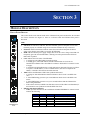
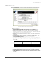
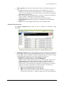
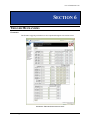
This section details each element found on the EX2500A front panel and describes the intended
use of these elements. See Figure 3-1 below as a reference while the EX2500A front panel is
discussed.
LEDs
•
•
•
•
•
•
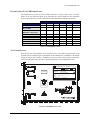
VXI ACC: the VXI access indicator, this LED will blink green for backplane accesses that
terminate properly. It will blink orange for accesses that terminate in retry or bus error.
SYSFAIL: indicates EX2500A SYSFAIL status (does not indicate backplane SYSFAIL
status). Note that the center LED is not used by the EX2500A.
PWR: indicates that the power supply voltages lines are at the correct voltage. This LED will
temporarily glow red when the EX2500A is initially powered up and when the VXI/LAN
RST button is pushed.
LAN: indicates the LAN status of the EX2500A.
o A solid green LAN LED indicates normal operation.
o A flashing green, LAN LED indicates that the EX2500A has received a device
identification command. The LAN LED will continue to flash until it is turned off via the
web page.
o A solid red LAN LED indicates that a LAN fault has been detected. This may be a failure
to acquire a valid IP address, to renew a DHCP IP lease, detection of a duplicate IP
address, or that the LAN cable has been disconnected.
1588: indicates the EX2500A’s IEEE 1588 synchronization status.
o A solid green 1588 LED indicates that the EX2500A’s device clock is an IEEE 1588
slave.
o A 1588 LED flashing green once per second indicates that its clock is the IEEE 1588
master.
o A 1588 LED flashing green once every two seconds indicates that the EX2500 is the
IEEE 1588 grandmaster.
o If the LED is solid red, an IEEE 1588 fault has occurred. If this LED is not illuminated, it
the EX2500A is not synchronized with the IEEE 1588 clock.
Ethernet Link Status Indicators
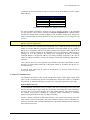
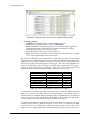
o A/B/C: provides link status for the established “GIGABIT ETHERNET” connection and
indicates the following:
bus
FIGURE 3-1:
EX2500A FRONT
PANEL
EX2500A Module Description
LED A
OFF
ON
OFF
OFF
ON
OFF
LED B
ON
OFF
OFF
ON
OFF
OFF
LED C
ON
ON
ON
OFF
OFF
OFF
Mode
1000 Mb/s Fiber, Link-up
1000 Mb/s Cat 5 Master, Link-up
1000 Mb/s Cat 5 Slave, Link-up
100 Mb/s Cat 5, Link-up
10 Mb/s Cat 5, Link-up
Link Down
21