1
MITSUBISHI ELECTRIC
MELSEC System Q
Programmable Logic Controllers
User's Manual
QJ71PB92D
PROFIBUS/DP Interface Module
Art. no.: 136267
10 04 2004
SH (NA) 08012
Version C
MITSUBISHI ELECTRIC
INDUSTRIAL AUTOMATION
• SAFETY PRECAUTIONS •
(Read these precautions before using.)
Before using this product, please read this manual and the relevant manuals introduced in this manual
carefully and pay full attention to safety to handle the product correctly.
The instructions given in this manual are concerned with this product. For the safety instructions of the
programmable controller system, please read the CPU module user's manual.
In this manual, the safety instructions are ranked as "DANGER" and "CAUTION".
DANGER
Indicates that incorrect handling may cause hazardous conditions,
resulting in death or severe injury.
! CAUTION
Indicates that incorrect handling may cause hazardous conditions,
resulting in medium or slight personal injury or physical damage.
!
Note that the ! CAUTION level may lead to a serious consequence according to the circumstances.
Always follow the instructions of both levels because they are important to personal safety.
Please save this manual to make it accessible when required and always forward it to the end user.
[DESIGN PRECAUTIONS]
!
DANGER
• When a communication error occurs in the PROFIBUS network, the status of the faulty station is
as follows. Configure an interlock circuit in the sequence program using the communication
status information (input X1, buffer memory 2040 to 2079) so that the system can operate
safely.
Erroneous outputs and mis-operation could cause accidents.
(1) The input data of the master station maintains the data before abnormality of the
communication.
(2) When the master station is down, the output state of each slave station will be in
accordance with the parameter settings.
(3) When any slave station is down, the output state of other slave stations will be in
accordance with the parameter settings of the master station.
• Do not output the "prohibited to use" signal as the output signal to an intelligent function module
from the PLC CPU.
Writing data into the "system area" or outputting a signal for "prohibited to use" may cause
system malfunction in the PLC.
• If a stop error occurs in the CPU module, the communication status is as described below.
(1) Communication with the slave station is continued.
(2) The input data received from the slave station are updated in the buffer memory of the
QJ71BP92D.
(3) For the output data sent from the QJ71PB92D to the slave station, the values at CPU
module stop error occurrence are held.
A-1
A-1
[DESIGN PRECAUTIONS]
!
CAUTION
• When the PROFIBUS cable is laid, do not lay it close to main circuits or power lines.
They should be installed 100mm(3.9inch) or more from each other.
Not doing so could result in noise that would cause malfunctioning.
[INSTALLATION PRECAUTIONS]
!
CAUTION
• Use the PLC in an environment that meets the general specifications contained in the CPU
user's manual.
Using this PLC in an environment outside the range of the general specifications may cause
electric shock, fire, malfunction, and damage to or deterioration of the product.
• When installing the module, securely insert the module fixing tabs into the mounting holes of the
base module while pressing the installation lever located at the bottom of the module downward.
Improper installation may result in malfunction, breakdown or the module coming loose and
dropping. Securely fix the module with screws if it is subject to vibration during use.
• Tighten the screws within the range of specified torque.
If the screws are loose, it may cause the module to fallout, short circuits, or malfunction.
If the screws are tightened too much, it may cause damage to the screw and/or the module,
resulting in fallout, short circuits or malfunction.
• Switch all phases of the external power supply off when mounting or removing the module.
Not ding so may cause electric shock or damage to the module.
• Do not touch the conductive area or electric parts of the module.
Doing so may cause module malfunctioning or breakdowns.
A-2
A-2
[WIRING PRECAUTIONS]
!
CAUTION
• Switch all phases of the external power supply of the PLC system off before connecting the
PROFIBUS cable. If you not switch off the external power supply, it will cause failure or
malfunction of the module.
• Be careful not to let foreign matter such as filings or wire chips get inside the module. These can
cause fire, breakdowns and malfunctioning.
• The PROFIBUS cable which is connected to the module must be protected with a duct or
secured in position with clamps.
Unless the cable is thus protected or secured, the module or the cable could be damaged when
the cable swings, moves or it is strained with careless pulls, or it could cause malfunction when
the cable contacts with any undesirable objects.
• When disconnecting the PROFIBUS cable from the module, do not pull by holding the cable
section. To disconnect the cable, make sure to hold the connector which is coupled with the
module. Do not attempt to pull the cable to disconnect it from the module. It could damage the
module or the cable, or cause malfunction due to a poor contact of the cable.
• Be sure to fix communication cables or power supply cables leading from the module by placing
them in the duct or clamping them.
Cables not placed in the duct or without clamping may hang or shift, allowing them to be
accidentally pulled, which may cause a module malfunction and cable damage.
[STARTING AND MAINTENANCE PRECAUTIONS]
!
DANGER
• Switch all phases of the external power supply off before cleaning.
Not doing so could cause electric shock.
!
CAUTION
• Never disassemble or modify the module.
This may cause breakdowns, malfunctioning, injury and/or fire.
• Switch all phases of the external power supply off before mounting or removing the module. If
you do not switch off the external power supply, it will cause breakdowns or malfunction of the
module.
• Set the ON/OFF select switch of the terminal resistor before the operation.
If the setting is switched during the operation, network error may occur, or error detection may
not be performed by error.
• Always make sure to touch the grounded metal to discharge the electricity charged in the body,
etc., before touching the module.
Failure to do so may cause a failure or malfunctions of the module.
A-3
A-3
[DISPOSAL PRECAUTIONS]
!
CAUTION
• When disposing of this product, treat it as industrial waste.
A-4
A-4
REVISIONS
* The manual number is given on the bottom left of the back cover.
Print Date
Dec., 2000
May, 2001
Apr., 2004
* Manual Number
Revision
SH (NA) 080127-A First printing
SH (NA) 080127-B Corrections
About the Generic Terms and Abbreviations, Section 2.1, 2.4, 4.1.3,
4.1.4, 5.1, 5.1.1, 5.4, 8.1, 8.2
SH (NA) 080127-C Corrections
Section 1.2, 2.1, 2.4, 3.1, 3.2.3, 3.3.2, 3.4.2, 4.1.4, 5.1, 5.1.1, 5.2.1, 5.3,
5.5.3, 6.1, 6.2, Chapter 7, Section 7.1, Chapter 9, Appendix 1,
Appendix 3
Additions
SAFETY PRECAUTIONS, About Manuals, Conformation to the EMC
Directive and Low Voltage Instruction, Section 7.1, Chapter 9
Japanese Manual Version SH-080126-C
This manual confers no industrial property rights or any rights of any other kind, nor does it confer any patent
licenses. Mitsubishi Electric Corporation cannot be held responsible for any problems involving industrial property
rights which may occur as a result of using the contents noted in this manual.
2000 MITSUBISHI ELECTRIC CORPORATION
A-5
A-5
INTRODUCTION
Thank you for purchasing the Mitsubishi Programmable Controller MELSEC-Q Series.
Before using the equipment, plese read this manual carefully to develop full familiarity with the functions and
performance of the graphic operation terminal you have purchased, so as to ensure correct use.
Please forward a copy of this manual to the end user.
CONTENTS
SAFETY PRECAUTIONS.............................................................................................................................A REVISIONS ...................................................................................................................................................A INTRODUCTION...........................................................................................................................................A CONTENTS...................................................................................................................................................A About Manuals ..............................................................................................................................................A Conformation to the EMC Directive and Low Voltage Instruction ...............................................................A About the Generic Terms and Abbreviations ...............................................................................................A Product Structure ..........................................................................................................................................A 1. OVERVIEW
1
5
6
6
8
9
9
9
1- 1 to 1- 2
1.1 Software Configuration ........................................................................................................................... 1- 1
1.2 QJ71PB92D Features............................................................................................................................ 1- 2
2. SYSTEM CONFIGURATION
2.1
2.2
2.3
2.4
2- 1 to 2- 5
Adaptive System ..................................................................................................................................... 2When Used in Multi-CPU System .......................................................................................................... 2Precautions for Configuring a System.................................................................................................... 2Confirmation of Serial No........................................................................................................................ 2-
3. SPECIFICATIONS
1
3
4
5
3- 1 to 3- 36
3.1 Performance Specifications .................................................................................................................... 3- 1
3.2 Network Configuration ............................................................................................................................ 3- 2
3.2.1 Basic configuration ........................................................................................................................... 3- 2
3.2.2 Applicable configuration................................................................................................................... 3- 3
3.2.3 Number of connectable slaves ........................................................................................................ 3- 7
3.3 I/O Signal................................................................................................................................................. 3-10
3.3.1 I/O signal list ..................................................................................................................................... 3-10
3.3.2 I/O signal detail description.............................................................................................................. 3-11
3.4 Buffer Memory List .................................................................................................................................. 3-15
3.4.1 Buffer memory/configuration............................................................................................................ 3-15
3.4.2 Buffer memory detailed description ................................................................................................. 3-16
4. FUNCTIONS
4- 1 to 4- 13
4.1 Functions for Exchanging with Slaves.................................................................................................... 44.1.1 Exchange flow .................................................................................................................................. 44.1.2 Global control functions.................................................................................................................... 44.1.3 Word data swap function ................................................................................................................. 44.1.4 I/O data separation prevention function .......................................................................................... 4A-6
A-6
1
2
3
6
8
4.2 Operation Mode ...................................................................................................................................... 4-11
4.2.1 Normal service mode (MODE 0) ..................................................................................................... 4-12
4.2.2 Extended service mode (MODE E) ................................................................................................. 4-13
5. PROCEDURES BEFORE SYSTEM OPERATION
5- 1 to 5- 12
5.1 Procedures before Operation ................................................................................................................. 5- 1
5.1.1 Parameter setting procedure ........................................................................................................... 5- 2
5.2 Installation ............................................................................................................................................... 5- 6
5.2.1 Handling precautions ....................................................................................................................... 5- 6
5.2.2 Installation environment ................................................................................................................... 5- 6
5.3 Part Names and Settings........................................................................................................................ 5- 7
5.4 Execution Method for Self-diagnosis...................................................................................................... 5- 9
5.5 Wiring....................................................................................................................................................... 5-10
5.5.1 PROFIBUS cable wiring................................................................................................................... 5-10
5.5.2 Terminator switch ............................................................................................................................. 5-10
5.5.3 Precautions against wiring ............................................................................................................... 5-11
5.6 Maintenance and Inspection................................................................................................................... 5-12
6. COMMUNICATION TIME
6- 1 to 6- 5
6.1 Bus Cycle Time ....................................................................................................................................... 6- 1
6.2 Transmission Delay Time ....................................................................................................................... 6- 5
7. PROGRAMMING
7.1
7.2
7.3
7.4
7.5
7- 1 to 7- 20
Communication Using Automatic Refresh Setting................................................................................. 7- 1
Normal Service Mode (MODE 0) Using FROM/TO Instruction............................................................. 7-11
Extended Service Mode (MODE E) Using FROM/TO Instruction......................................................... 7-14
Normal Service Mode (MODE 0) Using Dedicated Instruction ............................................................. 7-17
Execution of Global Control .................................................................................................................... 7-20
8. DEDICATED INSTRUCTIONS
8- 1 to 8- 2
8.1 BBLKRD Instruction ................................................................................................................................ 8- 1
8.2 BBLKWR Instruction ............................................................................................................................... 8- 2
9. TROUBLESHOOTING
9- 1 to 9- 3
9.1 Initialization of Flash ROM When Parameters are Corrupted ............................................................... 9- 2
APPENDIX
Appendix - 1 to Appendix - 3
Appendix 1 Differences between QJ71PB92D and AJ71PB92D/A1SJ71PB92D.........................Appendix - 1
Appendix 2 Extended Trouble Information of Mitsubishi's Slaves..................................................Appendix - 2
Appendix 3 Outline Drawings ..........................................................................................................Appendix - 3
INDEX
A-7
Index 1
A-7
About Manuals
The following are manuals related to this product.
Request for the manuals as needed according to the chart below.
Related Manuals
Manual Name
MELSoft GX Configurator-DP 4.00 Configuration System for Open Networks
Software Manual
Explains the overview, installation method, screen operations, etc. of GX Configurator-DP Version 4.
(Sold separately)
Manual Number
IB-65778
GX Configurator-DP Version 6 Operating Manual
Explains the overview, installation method, screen operations, etc. of GX Configurator-DP Version 6.
(Sold separately)
SH-080463ENG
Inquiries can be made to :
MITSUBISHI ELECTRIC EUROPE Factory Automation
Gothaer Strasse 8 D-40880 Ratingen Germany
Phone : +49(21 02)486-0
Fax : +49(21 02)486-717
A-8
A-8
Conformation to the EMC Directive and Low Voltage Instruction
For details on making the Mitsubishi PLC conform to the EMC directive and low
voltage instruction when installing it in your product, refer to Chapter 3 "EMC
Directive and Low Voltage Instruction" of the used CPU module User's Manual
(Hardware).
The CE logo is printed on the rating plate on the main body of the PLC that conforms
to the EMC directive and low voltage instruction.
No specific measures are required to make this product conform to the EMC
directive and low voltage instruction.
About the Generic Terms and Abbreviations
Unless otherwise specified, this manual uses the following generic terms and
abbreviations to describe the Type QJ71PB92D PROFIBUS-DP interface module.
Generic Term/Abbreviation
QJ71PB92D
QCPU (Q mode)
Base unit
GX Configrator-DP
PROFIBUS
Master station
Slave station
Peripheral device
Description of the abbreviation/general terms
Abbreviated name of Type QJ71PB92D PROFIBUS-DP interface module
Generic name of MELSEC-Q series PLC CPU module compatible with QJ71PB92D
Generic name of MELSEC-Q series main base unit and extension base unit
compatible with QJ71PB92D
Abbreviated name of configurator for PROFIBUS-DP
Abbreviated name of PROFIBUS-DP network
Abbreviated name of master station (class 1) (master device) inside PROFIBUS-DP
network
Abbreviated name of slave station (slave device) inside PROFIBUS-DP network
Generic name of personal computer capable of using GX Configuration-DP
Product Structure
The product structure of this product is given in the table below.
Model
QJ71PB92D
A-9
Product Name
Type QJ71PB92D PROFIBUS-DP interface module
Quantity
1
A-9
1 OVERVIEW
MELSEC-Q
1. OVERVIEW
1
This is the user's manual for the QJ71PB92D PROFIBUS-DP interface module
(hereafter abbreviated as " QJ71PB92D. When explain separately, however,
abbreviated as QJ71PB92D), which is used to connect a MELSEC-Q series
programmable controller to a PROFIBUS-DP network.
The QJ71PB92D operates as a master station (class 1) in the PROFIBUS-DP network.
1.1 Software Configuration
MELSEC Q Series PC
Automatic refresh,
FROM/TO,
Dedicated instruction
Portion where master
PCB is installed
Communication using a buffer memory
User Interface
Direct Data Link Mapper
(DDLM)
Portion where slave
PCB is installed
empty
Layer 3 to 7
Layer 2 Datalink layer
FDL
FMA1/2
PHY
Layer 1 Physical layer
The QJ71PB92D has a physical layer, data link layer, DDLM, and user interface that
conform to PROFIBUS-DP, and communicates data with the PLC CPU by using a
buffer memory.
The main application of PROFIBUS-DP is networks that execute high-speed
communication at the level of sensors and actuators.
1-1
1-1
1 OVERVIEW
MELSEC-Q
1.2 QJ71PB92D Features
1
(1) Operates as a PROFIBUS-DP master (class 1) station.
(2) Makes possible the exchange of input and output data to and from the slave
station without the need to be aware of the PROFIBUS-DP protocol by using I/O
signals X/Y and the buffer memory.
(3) Supports 3M, 6M, 12M [bps] network communication speeds in addition to the
9.6k, 19.2k, 93.75k, 187.5k, 500k, and 1.5M [bps] supported by the QJ71PB92D.
These can be selected using a configurator.
(4) Trouble information can be read from the slave station using the I/O signal X/Y
and the buffer memory.
(5) The global control function makes it possible to maintain all slave I/O at the same
time. In addition, this can also be canceled.
(6) The module contains a self-diagnosis function that can be used to test the
hardware such as the internal memory.
(7) The upper and lower bytes of I/O data can be swapped on the buffer memory.
When word data is handled, these bytes need not be swapped using the
sequence program.
(8) For data transmission between the PLC CPU and buffer memory of QJ71PB92D,
the automatic refresh setting and dedicated instruction are used to prevent I/O
data from being separated .
: The data of specified sizes are not matched with each other.
(9) Even when a plurality of PLC CPU modules are installed through the multi-CPU
system, this model can be controlled by any PLC CPU module.
1-2
1-2
2 SYSTEM CONFIGURATION
MELSEC-Q
2. SYSTEM CONFIGURATION
This chapter describes the system configuration of QJ71PB92D.
2.1 Adaptive System
2
The modules and software programs used on QJ71PB92D are shown below.
(1) Applicable modules and number of mountable modules
The following table indicates the CPU modules that can be used with the
QJ71PB92D and the number of mountable modules.
Applicable module
Q00JCPU
Q00CPU
Q01CPU
Number of mountable modules
Remarks
Max. 16 modules
( 1)
Max. 24 modules
Q02CPU
CPU module
Q02HCPU
Q06HCPU
Max. 64 modules
Available in Q mode only.
Q12HCPU
( 1)
Q25HCPU
Q12PHCPU
Q25PHCPU
Max. 64 modules
( 1)
1: Refer to the user's manual (function explanation/program fundamentals) of the used
CPU module.
(2) Mountable base units
The QJ71PB92D can be mounted on any I/O slot of the base unit.
However, since the power supply capacity may be insufficient depending on the
combination with the other mounted modules and the number of mounted
modules, be sure to check the power supply capacity when mounting the
modules.
(3) Compatibility with multiple CPU system
When using the QJ71PB92D in a multiple CPU system, first refer to the user's
manual (function explanation/program fundamentals) of the used CPU module.
(a) Compatible QJ71PB92D
When using the QJ71PB92D in a multiple CPU system, use the
QJ71PB92D of function version B or later.
(4) Online module change
The QJ71PB92D does not support the online module change.
2-1
2-1
2 SYSTEM CONFIGURATION
MELSEC-Q
(5) Essential configuration software
Set the parameters of the QJ71PB92D using the following configuration software.
System configuration
For use with the Q00J/Q00/Q01CPU
Configuration software
GX Configurator-DP Version 5.00A
or later
For use with the Q02/Q02H/Q06H/Q12H/Q25HCPU GX Configurator-DP Version 4.00A
For use with the Q12PH/Q25PHCPU
or later
POINT
Do not use the separation prevention function in CPU modules which do not
support this function or incorrect I/O data will result.
2-2
2-2
2
2 SYSTEM CONFIGURATION
MELSEC-Q
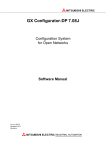
2.2 When Used in Multi-CPU System
When using QJ71PB92D in the multi-CPU system, take care of the following.
The control of QJ71PB92D is performed by any CPU.
A total of merely 64 sheets of QJ71PB92D is installed for each system. It is not the
mountable number of sheets for each controlled CPU, but the total number of sheets
controlled by all CPUs.
CPU CPU CPU CPU
1
2
3
4
2-3
1
2
3
4
5
6
7
8
9
10
11
12
13
14
15
16
17
18
19
20
21
22
23
24
61
62
63
64
65
2-3
2 SYSTEM CONFIGURATION
MELSEC-Q
2.3 Precautions for Configuring a System
(1) The following configuration software programs cannot be used on QJ71PB92D.
SW05F-PROFIMAP
MELSEC-PROFIMAP 1.0
MELSEC-PROFIMAP 2.0
MELSEC-PROFIMAP 3.0
(2) The separation prevention function can be used only on those products having
and subsequent.
QCPU (Q mode) with serial No. 02092
If this function is used on products that do not support it, incorrect I/O data will
result.
(3) When performing the following operations, ensure that the module READY signal
X1D of QJ71PB92D is turned ON beforehand.
To switch over the operation mode with Y11/X11, using the sequence program.
To set parameters.
If the status of X1D is ignored and data is read from or written in the buffer
memory, the CPU module may detect an error to stop the sequence calculation.
(4) Do not write parameters in QJ71PB92D simultaneously from a plurality of GX
Configurator-DPs.
The parameter values of QJ71PB92D will become incorrect ones.
(5) If remote parameter setting is performed from GX Configrator-DP to the
QJ71PB92D which is making data exchange, note that PROFIBUS data
exchange will stop during parameter setting.
(6) When setting parameters in GX Configurator-DPs, do not perform the mode
selection using a program.
The parameter setting or mode selection may not be performed correctly.
(7) Combination with MELSECNET/H
QJ71PB92D can be mounted on the MELSECNET/H administrative station and
general stations, but cannot be mounted on MELSECNET/H remote stations.
2-4
2-4
2 SYSTEM CONFIGURATION
MELSEC-Q
2.4 Confirmation of Serial No.
The serial Nos. of QCPUs (Q mode) capable of using the separation prevention
function of QJ71PB92D and their confirmation method are shown below.
(1) Serial Nos. of QCPUs (Q mode) capable of using the separation prevention
function
Products with serial No. 02092
and subsequent
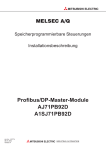
(2) Confirmation of serial Nos. of Q-series PLC
(a) When confirming on the Rating indication plate on the side surface of the
module
The serial No. of the applicable module is given in SERIAL column of the
Rating indication plate.
Serial No. (Upper 5 digits)
Function version
Conformed standard
(b) When confirming on GX Developer
The method for confirming the serial No. of the applicable module on GX
Developer is shown for the case using GX Developer Version 6. The serial
No. appears in the [Product information list] or [Module detail information]
window of GX Developer. The method of confirming the serial No. on the
Production information list window is shown below.
[Start Procedure]
"Diagnosis"
"System monitor"
"Product information list"
[Serial No.]
The serial No. of the applicable module appears in the Serial No. field.
2-5
2-5
3 SPECIFICATIONS
MELSEC-Q
3. SPECIFICATIONS
This section explains the QJ71PB92D the general specifications, performance
specifications, and transmission specifications.
For the general specifications of the QJ71PB92D, refer to the user’s manual for the
CPU module to be used.
3.1 Performance Specifications
Item
Specifications
Model
Master station (class 1)
Electrical standards and characteristics
Complies with EIA-RS485
Medium
Shielded twisted cable
Network configuration
Bus (however, tree type when a repeater is used)
Data link method
Token passing method (Master-to-master)
Polling method (Master-to-slave)
Transmission encoding method
NRZ
Transmission speed Transmission distance [m/segment]
Transmission specifications
3
QJ71PB92D
PROFIBUS-DP station type
Maximum transmission distance
when 3 repeaters are used
9.6 [kbps]
19.2 [kbps]
1200
4800
187.5 [kbps]
1000
4000
500 [kbps]
400
1600
1.5 [Mbps]
200
800
100
400
Transmission speed/maximum
93.75 [kbps]
transmission distance
1
2
3 [Mbps]
6 [Mbps]
12 [Mbps]
Maximum number of repeaters/network
3 units
Maximum number of stations/segment
32 stations
2
Maximum number of slave
stations/master station
60 slaves
3
3
Number of connection nodes (number of
32, 62 (1), 92 (2), 126 (3)
repeaters)
Transmittable data
Number of occupied I/O
3
32 bytes/1 station (Normal service mode)
244 bytes/1 station (Extended service mode)
32 points (I/O assignment : 32 Intelligent points)
5VDC internal current consumption
External dimensions
Weight
0.57A
105(H) × 27.4(W) × 975(D) [mm]
0.15kg
1 Transmission speed control within +/- 0.3% (PROFIBUS part 1)
2 Distance that the transmission distance can be expanded by (m/network) using repeaters
Maximum transmission distance (m/network) = (number of repeaters + 1) × transmission distance (m/segment)
3 When a slave used is greater than 32 bytes in the maximum data length of the error information, the maximum number of stations, the
maximum number of slave stations and the number of connection nodes may be less than the above values.
This is because the maximum data length of the slave station error information that the QJ71PB92D can receive varies with the
minimum station number and maximum station number of the slave stations set in the parameters. Refer to Section 3.2.3 for details.
For the noise immunity, withstand voltage, insulation resistance and others in the PLC system using this
module, refer to the power supply module specifications given in the used CPU module user’s manual.
3-1
3-1
3 SPECIFICATIONS
MELSEC-Q
3.2 Network Configuration
3.2.1 Basic configuration
1) Equipment types
Class 1 master
GX Configurator-DP
Slave
Repeater
2) Number of units that can be connected to the entire network (when repeaters are
used)
Master+slave ≤ 126 units
3) Number that can be connected for 1 segment
Master+slave+repeaters ≤ 32 units
4) Communications can be conducted via a maximum of 3 repeaters from an arbitrary
master or arbitrary slave to an arbitrary master or arbitrary slave (Not 3 units in the
entire network).
5) The maximum number of slaves that can be connected to 1 QJ71PB92D is 60
stations.
3
Master (class 1)
QJ71PB92D
CPU module
GX Configurator-DP
Slave
Slave
Slave
The PROFIBUS-DP cable is provided by the user.
3-2
3-2
3 SPECIFICATIONS
MELSEC-Q
3.2.2 Applicable configuration
1) When 1 master (class 1) station is connected
Master (class 1)
QJ71PB92D
CPU mlodule
GX Configurator-DP
Slave
Station No. 1
Slave
Station No. 2
Slave
Station No. 31
A maximum of 32 stations can be connected to 1 segment.
2) When 1 master (class 1) station and 1 repeater are connected
Master (class 1)
QJ71PB92D
CPU module
GX Configurator-DP
Slave
Station No. 1
Slave
Station No. 2
Slave
Station No. 30
Slave
Station No. 31
Slave
Station No. 32
Slave
Station No. 60
Repeater
In the above configuration a maximum of 60 slaves can be connected.
3-3
3-3
3 SPECIFICATIONS
MELSEC-Q
3) When 1 master (class 1) station and 3 repeaters are connected
Master (class 1)
QJ71PB92D
CPU module
GX Configurator-DP
Slave
Station No. 1
Repeater
Slave
Station No. 2
Slave
Station No. 18
Slave
Station No. 19
Slave
Station No. 35
Slave
Station No. 44
Slave
Station No. 36
Slave
Station No. 45
Repeater
Repeater
Slave
Station No. 60
In the above configuration a maximum of 60 slaves can be connected. The
difference between this configuration and the one in 2) is that the possible
communication distance can be extended.
3-4
3-4
3 SPECIFICATIONS
MELSEC-Q
4) When 126 master (class 1) and slave stations are connected
(When 60 or more slaves are connected)
1st master
(class 1)
2nd master
(class 1)
3rd master
(class 1)
CPU module
Repeater
Slave
Station No. 1
Slave
Station No. 14
Slave
Station No. 15
Slave
Station No. 18
Repeater
Slave
Station No. 19
Slave
Station No. 56
Repeater
Repeater
Slave
Station No. 57
Slave
Station No. 86
Slave
Station No. 107
Slave
Station No. 85
Slave
Station No. 108
Slave
Station No. 123
: This slave is controlled by the 1st master (class 1).
: This slave is controlled by the 2nd master (class 1).
: This slave is controlled by the 3rd master (class 1).
3-5
In the above configuration a maximum of 123 slave stations can be connected.
3-5
3 SPECIFICATIONS
MELSEC-Q
POINT
In configurations that use multiple master stations (multimaster configuration),
when reconnecting a cable after disconnecting a PROFIBUS cable for 1 master
that is exchanging data at a low baud rate, the communications of the master for
which the cable is not disconnected could stop and the slave output could be
turned off. To prevent this, the master PROFIBUS cable must be secured with a
screw.
In addition, there is a high possibility that the above phenomena can be avoided if
care is taken with the following points when configuring a system.
(1) Set the slave watchdog timer setting value to larger than (TTr × G)/BR.
However,
TTr : Target token rotation time (Unit: Bit Time)
G:
Gap update factor
BR : Baud rate (Unit: bps)
(2) Use a high baud rate.
(3) The HSA (Highest Station Address) value is made to match the maximum
station No. that is actually connected.
3-6
3-6
3 SPECIFICATIONS
MELSEC-Q
3.2.3 Number of connectable slaves
Please calculate the number of the slave which can be connected under the following
(1) and (2) conditions.
(1) Restrictions on maximum data length of slave station error
information
The maximum data length of the slave station error information that the
QJ71PB92D can receive varies with the minimum station number and maximum
station number of the slave stations set in the parameters, and can be calculated
using the following expression.
Maximum data length of acceptable error information [bytes] = Min
12600
, 244
N - 10
N = Min((a - b + 1) 5, 300)
a: Maximum station number of slave station
b: Minimum station number of slave station
Min(a, b) = A or B, whichever is smaller
If the maximum data length (Max_Diag_Data_Len) of the error information
described in the GSD file of a slave station is greater than the value calculated by
the above expression, normal communication may not be made with that slave
station.
If normal communication cannot be made, try the following methods:
(a) Set the station numbers of the slave stations with no unused numbers in
between.
(b) Make setting on the slave station side to shorten the maximum data length of
the error information. (If possible)
(c) Using two or more QJ71PB92D's, reduce the number of slave stations per
module.
(2) Restrictions on parameter data length of slave station
The parameter size which can be set in QJ71PB92D should meet the following
formula.
Note that the system construction which does not meet the following formula
causes the error of 1302H.
n
5+
(number of parameter blocks of each slave station)
128
i=1
n = number of slave stations
(number of parameter blocks of each slave station) = sum total of the numbers of parameter
blocks calculated by each slave station
The number of parameter blocks for each station is decided by the parameter
size of the station as follows.
Parameter size of each
slave station
246 bytes or less
247 to 480 bytes
481 to 720 bytes
721 to 762 bytes
3-7
Number of blocks of each
slave station
1 block
4 blocks
5 blocks
6 blocks
3-7
3 SPECIFICATIONS
MELSEC-Q
Calculate the parameter size of each slave station using the following formula.
Parameter size of each slave station = 31 + (User_Param data length)
+ (configuration data length) +
(a) User_Param data length
The value of User_Prm_Data usage on the screen displayed when Select
Modules is selected on the slave station setting screen of GX ConfiguratorDP.
(b) Configuration data length
The value differs depending on the slave station type as shown below.
1) Module type slave station
Sum of the number of Module set values, which are described in the
GSD file of the slave station, of the modules registered to the [slot]
Installed Module list.
(Example) [slot] Installed Module registration status of GX Configurator-DP
SD file description
Module="1 Word In,con word" 0x50
Number of set values is "1"
Module="1 Word Out,con word" 0x60
Number of set values is "1"
Configuration
data length is
"2".
2) Block type slave station
Number of Module set values described in the GSD file of the slave
station.
(Example) GSD file description
Module="1 Byte Out,3 Byte In" 0x20,0x12
As the number of set values
is "2", the configuration data
length is "2".
(c)
3-8
(constant)
= 2: When the slave station has only input or output
= 4: When the slave station has both input and output
3-8
3 SPECIFICATIONS
MELSEC-Q
(example)
When the system is constructed using only the stave stations with 520 bytes
parameter, QJ71PB92D can connect with up to the following number of the slave
stations.
When the parameter size is 520 bytes, the number of the parameter block is five
blocks.
5 + (5 n) 128
: n = number of slaves
n
128 - 5
= 24.6
5
n = 24
The calculation mentioned above tells that QJ71PB92D can connect with up to
24 slave stations.
Therefore, when 25 slave bureau or more are set by the parameter, QJ71PB92D
detects the error of 1302H.
3-9
3-9
3 SPECIFICATIONS
MELSEC-Q
3.3 I/O Signal
3.3.1 I/O signal list
The I/O signal configuration used in the QJ71PB92D and the data communications
with the PLC CPU are described below.
Signal direction: QJ71PB92D
Device No.
PLC CPU
Description
Signal direction: PLC CPU
Device No.
QJ71PB92D
Description
X00
Exchange start end signal
Y00
Exchange start request signal
X01
Communication trouble detection signal
Y01
Communication trouble detection signal reset
X02
Communication trouble area clear end signal
Y02
Communication trouble area clear request signal
X03
Not usable
Y03
Communication trouble area type selection
Global control request signal
Global control end signal
Y04
X05
Global control error end
Y05
Y0B
Not usable
Dedicated instruction valid signal
Y0D
Startup request signal
Y0E
X0F
X10
Operation mode signal
Y10
X11
Operation mode change completion signal
Y11
X1A
X1C
X1D
X1E
X1F
Not usable
Operation mode change request signal
Y12
Not usable
Communication READY signal
Not usable
Module READY signal
Not usable
Watchdog timer error signal
………………
…
X12
X1B
Not usable
Y0C
…
……………
X06
……
X04
Not usable
Y1F
POINT
If a device which is not usable is accidentally turned on and off in the sequence
program, it cannot guarantee as the QJ71PB92D function.
3 - 10
3 - 10
3 SPECIFICATIONS
MELSEC-Q
3.3.2 I/O signal detail description
(1) Exchange start request signal (Y00), exchange start end signal
(X00)
(a) After the exchange start request signal (Y00) is turned on by the sequence
program the exchange start end signal (X00) is turned on when cyclic
exchange starts.
(b) The exchange start end signal (X00) turns off in either of the following cases.
When the exchange start request signal (Y00) is turned off
When the parameters are written from GX Configurator-DP to the
QJ71PB92D
Maximum 200 ms
Exchange start request signal (Y00)
Exchange start
request
Exchange start end
Exchange start end signal (X00)
Exchange
(c) An interlock is used for FROM/TO of the I/O data.
(d) Before the exchange start request signal is turned on the output data initial
value must be written to the buffer memory.
(2) Communication trouble detection signal (X01), communication
trouble detection signal reset (Y01)
(a) The communication trouble detection signal (X01) is turned on when a
communication trouble occurs. At the same time the RSP ERR.'s LED turns
on. At this time the error code and detailed data are stored in the buffer
memory communication trouble area.
(b) The communication trouble detection signal (X01) is turned off when the
communication trouble detection signal reset signal (Y01) is turned on from
the sequence program or when communication failure is all resolved. At this
time, the RSP ERR. LED turns off.
(c) The communication trouble detection signal reset (Y01) is turned off by the
sequence program after it has been confirmed that the communication
trouble detection signal (X01) has been turned off.
(d) The following sequence is used.
Trouble detection reset
Communication trouble detection signal reset (Y01)
Trouble detection
Communication trouble detection signal (X01)
FROM/TO
FROM
The error code is read from the buffer memory to the PLC CPU.
3 - 11
3 - 11
3 SPECIFICATIONS
MELSEC-Q
(3) Communication trouble area clear request (Y02), communication
trouble area clear end (X02)
(a) The communication trouble area clear request (Y02) is turned on by the
sequence program when all of the communication trouble areas and
extension trouble areas are cleared.
(b) The communication trouble clear end signal (X02) is turned on after all of the
communication trouble area and extension trouble areas are cleared by
turning on the communication trouble area clear request signal (Y02).
(c) The communication trouble area clear request (Y02) is turned off by the
sequence program after it has been confirmed that the communication
trouble area clear end signal (X02) has been turned on.
(e) When the communication trouble area clear request signal (Y02) is turned off
the communication trouble area clear end signal is turned off.
(d) A sequence like the one below is used.
Clear request
Communication trouble area clear request (Y02)
Clear end
Communication troublev area clear end (X02)
(4) Global control request signal (Y04), global control end signal (X04)
(a) The global control end signal (X04) is turned on after service processing has
ended when the global control request signal (Y04) is turned on by the
sequence program.
(b) The global control request signal (Y04) is turned off by the sequence program
after it has been confirmed that the global control service end signal (X04)
has turned on.
(c) When the global control request signal (Y04) is turned off the global control
end signal (X04) turns off.
(d) The global control request signal (Y04) cannot be received if the exchange
starting (X00) is not on. If Y04 is turned on when X00 is off then both X04 and
X05 will turn on.
(e) A sequence like the one below is used.
Exchange start end signal (X00)
Global control request signal (Y04)
Global control end signal (X04)
X00
Global control request
Global control end
TO
Output data write
3 - 12
3 - 12
3 SPECIFICATIONS
MELSEC-Q
(5) Global control error end signal (X05)
(a) If global control is requested when exchange start (X00) is not on then global
control error end (X05) and the global control service end signal (X04) will
turn on at the same time.
(b) The slave I/O is not held/deleted when the global control error end signal
(X05) is on.
Global control request signal (Y04)
Global control request
Global control end
Global control end signal (X04)
Global control error end signal (X05)
Global control error end
(6) Operation mode signal (X10)
Indicates whether the current operation mode is the parameter setting mode or
not.
ON: Parameter setting mode
OFF: Normal service mode/extended service mode
(7) Operation mode change request signal (Y11), operation mode
change completion signal (X11)
Used to change the operation mode without resetting the CPU module.
(a) Operation mode change request signal (Y11)
OFF ¨ON: Requests the operation mode to be switched to the one specified in
the operation mode change request area (address 2255/8CFh) of
the buffer memory.
ON ¨OFF: Turns off X11.
(b)
Operation mode change completion signal (X11)
Turns on when the result is stored into the operation mode change result
area (address 2256/8D0h) of the buffer memory. This signal also turns on
on normal or abnormal completion of an operation mode change.
This signal turns off when Y11 turns from ON to OFF.
Exchange start
request signal: Y00
Operation mode change
request signal: Y11
Operation mode change
completion signal: X11
TO instruction
Sets the operation mode
in the "operation mode
change request area".
FROM instruction
Confirms the result in the
"operation mode change result
area" and "current operation mode".
IMPORTANT
When the operation mode change request signal (Y11) is on, do not turn off the
power or reset the CPU module during registration of the operation mode to the
flash ROM.
To do so may result in repair of the QJ71PB92D.
Turn the power off or reset the CPU module after the operation mode change
completion signal (X11) has turned on.
3 - 13
3 - 13
3 SPECIFICATIONS
MELSEC-Q
(8) Communication READY signal (X1B)
(a) This is turned on when the station enters the exchange start possible state
after the QJ71PB92D has started up and the module READY signal (X1D)
has turned on. (Only during the normal service mode (MODE O) and
extended service mode (MODE E).)
(b) This turns off when a exchange continuation impossible error occurs.
(c) The exchange start request signal (Y00) is used as an interlock when turned
on by the sequence program.
(9) Module READY signal (X1D)
(a) This is turned on when the QJ71PB92D is started up. regardless of the
operation mode at the time of starting.
(b) This is turned of when the QJ71PB92D goes down.
(10) Watchdog timer error end (X0D)
(a) This turns on when a Watchdog timer error occurs.
(b) The signal will not be turned off until the module is reset or the power of
QJ71PB92D is turned ON.
(11) Communication trouble area type selection (Y03)
(a) This signal is used to select the communication trouble area type (ring type or
fixed type).
ON: Fixed type
OFF: Ring type
(b) This signal becomes valid when the exchange start or communication trouble
area clear request (Y02) is ON.
Fixed type
selection
Communication trouble area
type selection (Y03)
(Becomes valid)
Ring type selection
Initial type
Exchange start or communication
trouble area clear request (Y02) on
(12) Dedicated instruction valid signal (Y0C)
(a) This signal is used when the dedicated instruction for separation prevention is
validated.
ON: Read/Write by dedicated instruction is validated.
OFF: Read/Write by dedicated instruction is invalidated.
(b) Keep the signal turned ON while the dedicated instruction is being used.
(13) Restart request signal (Y0D)
(a) When the QJ71PB92D goes down for some reason (when the FAULT LED
turns on and X1D is off) then turning Y0D from off to on to off again will make
it possible to restart the QJ71PB92D.
(b) The same state will be entered if after start up the power supply is turned off
and then on again.
3 - 14
3 - 14
3 SPECIFICATIONS
MELSEC-Q
3.4 Buffer Memory List
3.4.1 Buffer memory/configuration
The configuration of the buffer memory used to receive and send data with the
QJ71PB92D and the PLC CPU is described below.
Buffer memory address
decimal (Hexadecimal)
0
(0H)
959
(3BFH)
960
(3C0H)
1919
(77FH)
1920
(780H)
2039
(7F7H)
2040
(7F8H)
Area name
Description
Input area
This is the area that stores the input data from the slave.
Output area
This is the area that stores the output data to the slave.
Address information area
This is the area that shows the slave address and I/O data length.
Communication trouble area
This is the area that shows the trouble information that occurred during
communication.
2079
(81FH)
2080
(820H)
Slave error information cancel area
This is the area that sets the data that masks the slave trouble information.
2081
(821H)
Global control area
This is the global control function hold/cancel selection area.
2082
(822H)
Not usable
2083
(823H)
Time out time setting area (Closed to users
because this is a debugging function.)
This is used to set the time out time when an exchange start/stop is executed.
2084
(824H)
Trouble no information time setting area
This is used to set the time that does not inform the communication trouble
after the exchange start.
2085
(825H)
Not usable
2095
(82FH)
2096
(830H)
Expansion communication trouble area
2110
(83EH)
2111
(83FH)
Not usable
2112
(840H)
Slave status area
2116
(844H)
2117
(845H)
2127
(84FH)
2128
(850H)
Not usable
Input/Output start address area (Extended
service mode only)
This area shows the expansion information of the trouble information which is
occurred during the communication.
This is the area that shows the status information of each slave.
This is the area that shows the addresses to start the input area and output
area of each slave.
2247
(8C7H)
2248
(8C8H)
2253
(8CDH)
2254
(8CEH)
Current operation mode area
This area indicates the operation mode of the QJ71PB92D when it has started
up.
2255
(8CFH)
Operation mode change request area
In this area, set the operation mode of the QJ71PB92D which you want to
choose.
2256
(8D0H)
Operation mode change result area
This area indicates the execution result of the operation mode change
request.
2257
(8D1H)
Local station address display area
Area in which the station address of the local station is stored.
2258
(8D2H)
Self-diagnosis status code area
Area in which the code indicating the status of the self-diagnosis during the
execution of the diagnosis is stored.
2259
(8D3H)
3775
(EBFH)
Not usable
Not usable
POINT
Don't read and write to the buffer memory which is not usable.
If you perform it, it cannot guarantee as the QJ71PB92D function.
3 - 15
3 - 15
3 SPECIFICATIONS
MELSEC-Q
3.4.2 Buffer memory detailed description
(1) INPUT area (Buffer memory address: 0 (0H) to 959 (3BFH))
Either the normal service mode (Mode 0) or extended service mode (Mode E)
can be selected using GX Configurator-DP.
(a) Normal service mode (MODE 0)
This is the area that stores the input data from the slave station.
This area is fixed to an allocation of 32 bytes (16 words) per station for a
total of 60 stations worth. This input area configuration is as follows.
Example : When the input data length for the first station is set to 29 bytes
and that for the second station to 32 bytes
(Upper byte)
(Lower byte)
1st station 2nd byte
1st station 1st byte
1st station 4th byte
1st station 3rd byte
b15
Buffer memory
0(0H)
address decimal
(Hexadecimal)
15(FH)
1st station input data
Buffer memory 0(0H)
address decimal
(Hexadecimal)
1(1H)
b0
16(10H)
1
2nd station input data
31(1FH)
14(EH)
1st station 29th byte
15(FH)
n th station input data
16(10H)
2nd station 2nd byte
2nd station 1st byte
17(11H)
2nd station 4th byte
2nd station 3rd byte
1
944(3B0H)
60th station input data
959(3BFH)
30(1EH) 2nd station 30th byte
2nd station 29th byte
31(1FH) 2nd station 32nd byte
2nd station 31st byte
b0
b15
: Free area (00H)
1 Since the data area is fixed to 32 bytes,
all unused areas will become free.
POINT
The input data of the slave station, which was disabled from communication during
normal communication and whose corresponding bit of the communication status
area 1 turned ON (1), is not stored into the input area of the QJ71PB92D.
In the input area of the corresponding slave station, the data before communication
failure is held.
1: Indicates the area of buffer memory addresses 2113 (841H) to 2116 (844 H) in
the slave status area.
3 - 16
3 - 16
3 SPECIFICATIONS
MELSEC-Q
(b) Extended service mode (MODE E)
This is the area that stores the input data from the slave station.
In this area, the data length (in byte units) for each station is assigned in
variable length according to the parameter file set in the GX Configrator-DP.
The data length can be set in the range of 0 to 244 bytes.
Number of stations that can be set will vary in the range of 1 to 60,
depending on the specified data length. For example, seven stations can be
set if the data length for each station is 244 bytes, and 60 stations if the data
length is 32 bytes.
Example : When the input data length for the first station is set to 23 bytes
and that for the second station to 7 bytes
Buffer memory
address decimal
(Hexadecimal)
Buffer memory
address decimal
(Hexadecimal)
b15 (Upper byte)
0(0H)
(Lower byte)
b0
0(0H)
1st station 2nd byte
1st station 1st byte
1(1H)
1st station 4th byte
1st station 3rd byte
1st station input data
11(BH)
12(CH)
2nd station input data
15(FH)
n th station input data
10(AH) 1st station 22nd byte
1st station 21st byte
11(BH)
1st station 23rd byte
2nd station 1st byte
13(DH) 2nd station 4th byte
2nd station 3rd byte
2nd station 6th byte
2nd station 5th byte
14(EH)
60th station input data
2
2nd station 2nd byte
12(CH)
2nd station 7th byte
15(FH)
b0
b15
: Free area (00H)
2 When the data lenghth is set to an odd number
of bytes, the last upper byte becomes a free area
and data for the next station is assugned from
the next address.
POINT
The input data of the slave station, which was disabled from communication during
normal communication and whose corresponding bit of the communication status
area 1 turned ON (1), is not stored into the input area of the QJ71PB92D.
In the input area of the corresponding slave station, the data before communication
failure is held.
1: Indicates the area of buffer memory addresses 2113 (841H) to 2116 (844 H) in
the slave status area.
3 - 17
3 - 17
3 SPECIFICATIONS
MELSEC-Q
(2) OUTPUT area (Buffer memory address: 960 (3C0H) to 1919
(77FH))
Either the normal service mode (Mode 0) or extended service mode (Mode E)
can be selected using GX Configurator-DP.
(a) Normal service mode (MODE 0)
This is the area that stores the output data to the slave station.
This area is fixed to an allocation of 32 bytes (16 words) per station for a
total of 60 stations worth. This output area configuration is as follows.
Example : When the output data length for the first station is set to 1 bytes
and that for the second station to 3 bytes
Buffer memory
address decimal
(Hexadecimal) b15
Buffer memory
address decimal
(Hexadecimal)
960(3C0H)
(Upper byte)
960(3C0H)
b0
(Lower byte)
1st station 1st byte
1st station output data
961(3C1H)
975(3CFH)
976(3D0H)
1
2nd station output data
991(3DFH)
974(3CEH)
975(3CFH)
n th station output data
976(3D0H)
2nd station 2nd byte
977(3D1H)
2nd station 1st byte
2nd station 3rd byte
1
1904(770H)
60th station output data
1919(77FH)
991(3DFH)
b0
b15
: Free area (00H)
1 Since the data area is fixed to 32 bytes,
all unused areas will become free.
3 - 18
3 - 18
3 SPECIFICATIONS
MELSEC-Q
(b) Extended service mode (MODE E)
This is the area that stores the output data to the slave station.
In this area, the data length (in byte units) for each station is assigned in
variable length according to the parameter file set in the GX Configrator-DP.
The data length can be set in the range of 0 to 244 bytes.
Number of stations that can be set will vary in the range of 1 to 60,
depending on the specified data length. For example, seven stations can be
set if the data length for each station is 244 bytes, and 60 stations if the data
length is 32 bytes.
Example : When the output data length for the first station is set to 19 bytes
and that for the second station to 5 bytes
Buffer memory
address demical
(Hexadecimal)
Buffer memory
address demical
(Hexadecimal) b15
960(3C0H)
1st station output data
969(3C9H)
b0
(Upper byte)
(Lower byte)
960(3C0H)
1st station 2nd byte
1st station 1st byte
961(3C1H)
1st station 4th byte
1st station 3rd byte
968(3C8H)
1st station 18th byte
1st station 17th byte
970(3CAH)
2nd station output data
972(3CCH)
1st station 19th byte
969(3C9H)
n th station output data
2
970(3CAH)
2nd station 2nd byte
2nd station 1st byte
971(3CBH)
2nd station 4th byte
2nd station 3rd byte
972(3CCH)
60th station output data
2nd station 5th byte
b0
b15
: Free area (00H)
2 When the data lenghth is set to an odd number
of bytes, the last upper byte becomes a free area
and data for the next station is assugned from
the next address.
3 - 19
3 - 19
3 SPECIFICATIONS
MELSEC-Q
(3) Address information area (Buffer memory address: 1920 (780H) to
2039 (7F7H))
This area shows the station address, input byte length, and output byte length for
each slave station. This allocation is set by the GX Configrator-DP. The station
addresses for the 1st through the 60th stations are stored in the order of
registration in the GX Configrator-DP. (Station addresses: 1 to 126, do not need
to be sequential numbers.)
The address information area configuration is shown below. For details refer to
Section 3.4.2 (4).
Buffer memory
address demical
(Hexadecimal)
1920(780H)
Station address of 1st station
1921(781H) 1st station input byte length
1922(782H)
1st station output byte length
Station address of 2nd station
1923(783H) 2nd station input byte length
2nd station output byte length
Station address of n station
n th station input byte length
2036(7F4H)
Station address of 59th station
2037(7F5H) 59th station input byte length
2038(7F6H)
n th station output byte length
59th station output byte length
Station address of 60th station
2039(7F7H) 60th station input byte length
60th station output byte length
(a) The station address of unallocated stations is FFFFH, and the I/O byte is
FFH.
(b) When the I/O byte length of allocated stations is 0, a 0 is stored for the byte
length.
(c) The n does not show the station address but represents a number (the nth
number) used for the input/output area.
3 - 20
3 - 20
3 SPECIFICATIONS
MELSEC-Q
(4) Example address information area, INPUT area, and OUTPUT
area
The QJ71PB92D reads the slave station address and I/O byte length set by the
parameter file which is set by the GX Configrator-DP and stores these in the
buffer memory address information area.
With the QJ71PB92D, I/O areas are assigned to each slave station based on the
I/O byte length information in the address information area, and each I/O data will
be stored in the corresponding buffer memory area (MODE E).
Example : At extended service mode
IN P U T
Buffer memory
address demical
(Hexadecimal) b15
INPUT/OUTPUT area
b0
Buffer memory
address demical
(Hexadecimal) b15
0(0H)
1st station 2nd input byte 1st station1st input byte
1920(780H)
1(1H)
1st station 3rd input byte
1921(781H)
2(2H) 2nd station 2nd input byte 2nd station 1st input byte
1922(782H)
3(3H) 2nd station 4th input byte 2nd station 3rd input byte
1923(783H)
Address information area
b0
5
3
1
0
2
3
10
7
5
4(4H) 2nd station 6th input byte 2nd station 5th input byte
2nd station 7th input byte
5(5H)
1 Station address (FFFFH if not assigned)
2 Input byte length (FFH if not assigned)
3 Output byte length (FFH if not assigned)
1, 2 and 3 are also set in a reserved station.
6(6H)
959(3BFH)
960(3C0H) 2nd station 2nd output byte 2nd station 1st output byte
OUTPUT
961(3C1H) 2nd station 4th output byte 2nd station 3rd output byte
4
962(3C2H)
2nd station 5th output byte
: Vacant area
(The free areas in the INPUT area
are initialized with [00H].)
963(3C3H)
1919(77FH)
4 Since output from the first station has a byte length of 0,
no area is allocated in the OUTPUT area.
CPU module
QJ71PB92D
PROFIBUS-DP
network
Slave
Station address : 10
Input data length : 7 byte
Output data length : 5 byte
3 - 21
Slave
Station address : 5
Input data length : 3 byte
Output data length : 0 byte
3 - 21
3 SPECIFICATIONS
MELSEC-Q
(5) Communication trouble area (Buffer memory address: 2040 (7F8H)
to 2079 (81FH))
When some kind of trouble occurs during communication the QJ71PB92D stores
the contents of the trouble in this area. Fixed type or ring type can be selected for
this area by turning the communication trouble area type selection (Y03) on or off
(refer to Section 3.3.2 (11)).
As shown in the following diagram, a total of 8 pieces of trouble information that
consist of the trouble code, detailed data length, and detailed data can be stored
in the basic configuration regardless of whether for fixed or ring data.
Ring type data is stored in order from the header with the header always being
the latest trouble information.
With fixed type data, when 8 pieces of trouble information are stored the areas 2
to 8 (data 1 to 7) are fixed, so when the next new trouble occurs only header area
1 (data 8) is updated.
All trouble information for either type can be cleared by turning on the
communication trouble detection signal reset (X01). Communication trouble area
clear request (Y02) is on, the contents of the communication trouble area are
hold though the communication trouble detection signal (X01) turns off.
The communication trouble area configuration is as follows.
(a) Communication trouble area configuration
Buffer memory
address demical
(Hexadecimal)
2040(7F8H)
2044(7FCH)
2045(7FDH)
Buffer memory
address demical
(Hexadecimal)
Trouble information area 1
2041(7F9H)
2042(7FAH)
Trouble information area 2
2049(801H)
2050(802H)
2054(806H)
2075(81BH)
2040(7F8H)
2043(7FBH)
2044(7FCH)
Error code (refer to the next page.)
Detailed data length (0 to 3)
Detailed data 1
Detailed data 2
Detailed data 3
Trouble information area 3
Trouble information area 8
Ring type
2079(81FH)
Trouble
information area 1
Trouble
information area 2
Data 1
Data 2
Data 8
Data 9
Data 1
Data 7
Data 8
Data 1
Data 2
Data 2
Data 8
Data 9
Data 1
Data 7
Data 7
Data 1
Data 1
Fixed type
Trouble
information area 8
Trouble
information area 1
Trouble
information area 2
Trouble
information area 8
3 - 22
Data 1
3 - 22
3 SPECIFICATIONS
MELSEC-Q
(b) Error codes
The error codes are shown below.
Detailed data
Error
Code
Data
length
1
2
3
0200H
(c)
Ref.
(c)
Ref.
(c)
Ref.
(c)
Ref.
(c)Ref.
1211H
1
03h
The slave address specified in the parameter is
the same as that of the master. This error occurs
immediately after the power supply is turned on or
the CPU is reset. Even though this error is
occurring, if the exchange start (Y00) is on then
error of error code 3000H will occur, the FAULT
LED will turn on, and operation will stop.
1300H
1
Contents Contents
ref.
ref.
Not even 1 active slave station is set in the
parameter. When this error occurs the detailed
data is set to:
Detailed data 1: Number of slaves set in the
parameter.
This error occurs immediately after the power
supply is turned on or the CPU is reset. Even
though this error is occurring, if the exchange
start (Y00) is on then error of error code 3000H
will occur, the FAULT LED will turn on, and
operation will stop.
1) Set 1 or more active
slaves in the
parameter.
2) When the FAULT
LED is turned on,
reset is enabled by
turning OFF ON
OFF the Y0D
1301H
1
Ignored
The parameter area space is insufficient.
Reduce the number of
connected stations or
change the slave
station type.
3000H
1
Ignored
1) When the above errors 1211 H or 1300 H have
occurred before this error:
Refer to errors 1211 H, 1300 H above.
2) Otherwise
An unexpected error has occurred.
For 1)
Refer to the above
1211 H, 1300 H
errors.
For 2)
Contact the nearest
Mitsubishi Electric
branch office or
dealer.
: Exchange stops after the error occurs.
3 - 23
Communication state
Description
User processing
(c)Ref.
: Exchange continues.
3 - 23
3 SPECIFICATIONS
MELSEC-Q
(c) When the trouble code = 0200H
For a slave trouble information occurrence (error code = 0200H), the slave
trouble information is stored in the detailed data. The communication trouble
area configuration for this case is shown below. In addition, the expansion
communication trouble information is stored in buffer memory 2096 to 2110
for only the latest trouble information of the error code = 0200H trouble
information. For information regarding the expansion communication trouble
information refer to Section 3.4.2 (6).
Error code = slave trouble information occurrence
Detailed data length = 3
Detailed data 1
Master address ( 1)
Slave address ( 2)
Detailed data 2
Trouble information
Detailed data 3
Slave ID ( 3)
1 The station address of the master station that controls the slave station in which this
trouble information occurred is stored. However, FFH is stored when the trouble
information shows the exchange with the slave is failed.
2 The station address of the slave station in which this trouble information occurred is
stored.
3 Individual slave inherent ID No. from the PNO is stored. However, FFH is stored for
trouble information that shows that the exchange with the slave failed.
The trouble information is shown in a 16-bit bit string, and the bits that correspond to
the respective trouble occurrences are set. A description of the error information is
given below.
bit
Description
15
Controlled by another master.
14
The parameter transmitted by the master is
incorrect.
The response from the slave is incorrect.
The function requested by the master is not
supported.
Expansion trouble information exists.
The I/O byte size parameter received from the
master does not match that of the slave.
The slave is not ready to exchange.
13
12
11
10
9
8
7
6
5
4
3
2
1
0
Communication state
Multiple masters are trying to communicate with the same
slave, so recheck the parameter.
Check the parameter.
Check the slave or network status.
Check the slave specifications. Especially if global control is
supported.
Check the slave status. (refer to Section 3.4.2 (6).)
Check the slave parameter.
Exchange with the slave cannot be
conducted.
Separated from the cyclic exchange by the
parameter setting.
0 (reserved)
The slave has entered the SYNC mode.
The slave has entered the FREEZE mode.
Watchdog monitoring is being conducted in
the slave.
0 (fixed)
Diagnostic data read request.
Parameter allocation request from a slave.
Processing
This trouble information will always occur at exchange start,
so it can be ignored. If this trouble occurs during exchange,
check the slave status and communication circuit.
Check the slave status and communication circuit. And
check the parameter.
This trouble information will always occur at exchange start,
so it can be ignored. Check if the parameter on the network
was changed by a class 2 master.
(Normal operation)
(Normal operation)
(Normal operation)
Setting
station
Master
Slave
Master
Slave
Master
Slave
Slave
Master
Master
Slave
Slave
Slave
Slave
Slave
Check the slave statue.
Slave
This error information will always occur at exchange start, so Slave
it can be ignored. If this error occurs during exchange, check
the slave status and communication circuit.
: Exchange continues even if trouble occurs.
3 - 24
3 - 24
3 SPECIFICATIONS
MELSEC-Q
(6) Expansion communication trouble area (Buffer memory address:
2096 (830H) to 2110 (83EH))
This area shows the latest expansion trouble information for only one of the latest
expansion trouble information in the error code 0200H error information stored in
buffer memory 2040 to 2079 communication error area (Refer to Section 3.4.2
(5)).
Communication trouble area
(When fixed buffer is selected.)
Area 1
Data 10
Area 2
Data 7
No error code=0200H
expansion trouble
information (trouble
information bit 11 = 0)
Buffer memory
address demical
(Hexadecimal)
Expansion trouble information area
2096 (830H)
2097 (831H)
Data 6
(Latest data)
Data 5
There is error code=
0200H expansion
trouble information
(trouble information
bit 11 = 1)
Data 4
Data 3
Data 2
2110 (83EH)
Area 8
Data 1
(a) Buffer Memory 2096 (830H)
The latest expansion communication trouble information length stored from
buffer memory 2098 is stored as a byte length unit.
Buffer memory
address demical Expansion trouble information area
(Hexadecimal)
9096 (830H)
21
9097 (831H)
9098 (832H)
21 bytes = 10 words + 1 byte
2110 (83EH)
3 - 25
3 - 25
3 SPECIFICATIONS
MELSEC-Q
(b) Buffer memory 2097 (831H)
Only bit 7 is valid. Other bit is fixed in 0. Bit 7 is turned on when the slave
sends expansion trouble information that is 27 bytes or more.
MSB
Bit position
15
LSB
14
13
12
11
10
9
8
7
6
5
4
0 fixed
3
2
1
0
0 fixed
(c) Buffer memory 2098 to 2110 (832H to 83EH)
The following informations are stored in this area:
Device related trouble information
This area stores the slave station inherent self-diagnostic information that
is not set by the PROFIBUS-DP standards.
Identifier related trouble information
For module type slave stations, whether or not a module error has
occurred is stored as bit information.
Channel related trouble information
For module type slave station, this stores the, error information of all
modules outputting an error.
1) Device Related trouble information
This stores the slave module inherent trouble information that is not set
by the PROFIBUS-DP standards. The device related trouble can be
divided by header and trouble information. This area stores a 2 bit
value that is the device related trouble information in the header,
including the header (1 byte), and the device related trouble information
for this area.
Buffer memory
address demical
(Hexadecimal)
Header:
2098 (832H)
(2nd byte)
MSB
Header
(1st byte)
Bit position
2099 (833H)
(4th byte)
7
LSB
6
5
4
3
2
1
0
(3rd byte)
Device area length 2 to 63 in byte units
Bits 6 and 7 are set to 00.
3 - 26
3 - 26
3 SPECIFICATIONS
MELSEC-Q
2) Identifier related trouble information
For module type slave stations, this stores as bit information whether or
not a module is outputting an error. The identifier related trouble
information can be divided into header and trouble information. This
area stores a 2 bit value that is the identifier related trouble information
in the header, including the header (1 byte), and the device related
trouble information for this area.
(End of device area)
Buffer memory
Header:
Header
(1st byte)
(2nd byte)
Bit position
(4th byte)
MSB
7
LSB
6
5
4
3
2
1
0
(3rd byte)
Identifier area length 2 to 63 in byte units
Bits 6 and 7 are set as 01.
MSB
Bit position:
2nd byte
7
3rd byte
15
LSB
6
5
4
3
2
1
0
When this bit is 1, the 0th module has an error.
When this bit is 1, the 7th module has an error.
3 - 27
14
13
12
11
10
9
8
3 - 27
3 SPECIFICATIONS
MELSEC-Q
3) Channel related trouble information
When a module type slave station, this area stores the trouble
information for each module that is outputting an error. This area does
not have a header and stores this information at the end of the identifier
related trouble information. Each channel trouble information consists
of an identifier No., channel No., and error type of 3 bytes.
(End of identifier area)
Buffer memory
1st byte: Identifier No.
(2nd byte)
channel No.1
7
Bit position
(4th byte)
identifier No.2
(3rd byte)
trouble type 1
(6th byte)
trouble type 2
(5th byte)
channel No.2
LSB
MSB
(1st byte)
identifier No.1
6
5
4
3
2
1
0
Identifier Nos. 0 to 63
bits 6 and 7 are set to 10.
2nd byte: Channel No.
LSB
MSB
Bit position
7
6
5
4
3
2
1
0
Input/output
00 = Reserved
01 = Input
10 = Output
11 = Input/output
Channel number 0 to 63
3rd byte: Trouble type
LSB
MSB
Bit position
7
6
5
Channel type
000 = Reserved
001 = Bit
010 = 2 bit
011 = 4 bit
100 = byte
101 = Word
110 = 2 words
111 = Reserved
3 - 28
4
3
2
1
0
Error type:
0 Reserved
1 Short circuit
2 Voltage too low
3 Voltage too high
4 Overload
5 Temperature too high
6 Disconnected wire
7 Upper limit exceeded
8 Lower limit exceeded
9 Error
10 Reserved
15 Reserved
16 Manufacturer
31 Manufacturer
3 - 28
3 SPECIFICATIONS
MELSEC-Q
4) Identifier No., channel No.
The slave identifier No. and channel No. are discussed below. The
identifier No. is the No. that is attached from the header of each slave
module. Each module can have multiple channels. Refer to the each
slave specifications regarding to the channel numbering method.
Slave
16 point
DI
byte
2 channels
32 point
DO
byte
4 channels
32 point
DO
2 words
1 channels
PROFIBUS-DP
network
Slot
No.
Identifier No.
Channel No.
3 - 29
0
0
0,1
1
1
0,1,2,3
2
2
0
3 - 29
3 SPECIFICATIONS
MELSEC-Q
(7) Example expansion communication trouble area
Buffer memory
address demical
(Hexadecimal)
Expansion communication trouble information length (byte length)
2096(830H)
00 Header (length 4)
2098(832H)
Device
0
01
01
: Vendor independent trouble information
01 Header (length 4)
Identifier
0
Identifier Nos. 0 and 2 have trouble information.
0
01
00
00
01
10
00
00
00
10
00
00
10
10
00
01
00
11
00
01
11
10
00
00
00
Channel
10
Identifier No.0 and
channel No. (slot) 1 correspond,
channel type: byte, error: overload.
Identifier No.2 and
channel No. (Slot) 0 correspond,
channel type: 2 words, error: exceeds high limit value
Slave
16 point
DI
byte
2 channels
32 point
32 point
DO
DO
2 word
byte
4 channels 1 channels
PROFIBUS-DP
network
Slot
No.
Identifier No.
Channel No.
3 - 30
0
0
0,1
1
1
0,1,2,3
2
2
0
3 - 30
3 SPECIFICATIONS
MELSEC-Q
(8) Slave trouble information cancel area (Buffer memory address:
2080 (820H))
This stores the value that masks the slave trouble information (error code =
0200H detailed data 2). Even if the slave trouble information corresponding to this
area bit occurs the slave trouble information detection signal (X01) and RSP
ERR. LED do not turn on. In addition, the trouble information is not stored in the
trouble information area. The default value is 02B9H.
This 02B9H trouble information also occurs during normal situations and is
masked. This value can only be changed when exchange start is off. (When on,
changes are ignored.)
Buffer memory
address demical
b15
(Hexadecimal)
2080(820H)
b0
Slave trouble information mask value
Slave trouble information
bit
To mask this
trouble information
Controlled by another master.
14
The parameter sent by the master is incorrect.
13
The response from the slave is incorrect.
12
The function requested by the master is not supported.
11
Expansion trouble information exists.
10
bit
Buffer memory
address demical 15
(Hexadecimal)
2080(820H)
3 - 31
0
Description
15
The environment data received from the master does not match that of the slave.
9
The slave is not ready to exchange.
8
Cannot exchange with slave.
7
Separated from the cyclic exchange by the parameter.
6
0 (reserved)
5
The slave has entered the SYNC mode.
4
The slave has entered the FREEZE mode.
3
Watchdog timer monitoring is being conducted in the slave.
2
0 (fixed)
1
Diagnostic data read request
0
Parameter allocation request from the slave
bit
14
13
12
11
10
9
8
7
6
5
4
3
2
1
0
0
0
0
0
0
1
0
1
0
1
1
1
0
0
1
= Set to 02B9H.
3 - 31
3 SPECIFICATIONS
MELSEC-Q
(9) Global control area (Buffer memory address: 2081 (821H))
The buffer memory (2081(821H)) value and corresponding command table are
shown below.
Bit
position
Value
(valid/invalid)
Command
Description
8 to 15
1/0
Group 1 to 8 selection
Bits 8 to 15 correspond respectively to groups 1 to 8 and
shows that the bit value is transmitted by the global control
command to the 1 group (refer below). More than one
group at a time can be selected from groups 1 to 8.
When all bits 8 to 15 are 0, global control commands are
sent to all the slaves.
5
1/0
SYNC
4
1/0
UNSYNC
The actual output data hold is canceled.
3
1/0
FREEZE
The actual input data is held and read.
2
1/0
UNFREEZE
The actual input data hold is canceled.
Bit position
15
14
13
12
11
The actual output data is written and held.
10
9
8
7
6
5
4
3
2
1
0
: 0 or 1
UNFREEZE
Group 1
Group 2
Group 3
FREEZE
UNSYNC
Group 4
SYNC
Group 5
Group 6
Group 7
Group 8
Bit specifications for UNSYNC/SYNC and UNFREEZE/FREEZE
Bit position
Command
5
4
3
2
0
0
0
0
0
0
0
0
1
0
1
0
0
1
0
0
0
1
0
1
0
UNSYNC
FREEZE
UNFREEZE
1
1
1
SYNC
1
1
0
1
0
1
: 0 or 1
: Conducted
: Not conducted
3 - 32
3 - 32
3 SPECIFICATIONS
MELSEC-Q
(10) Trouble no information time setting area (Buffer memory address:
2084 (824H))
Set the time at seconds unit, which does not inform the communication trouble
after the exchange start. Default value is 20 seconds so the communication
trouble is not informed for 20 seconds after the exchange start. By this setting, in
case the master power supply ON is faster than the slave power supply ON etc.,
it makes possible to prohibit an error that occurs temporary when system starts
up.
(11) Slave status area (Buffer memory address: 2112 (840H) to 2116
(844H))
This is the area that stores the status of each slave station.
The following figure shows the configuration:
Communication
status area
for all stations
Communication
status area for
individual stations
Buffer memory
address demical
(Hexadecimal)
b15
b0
2112(840H) Communication status (all stations)
2113(841H)
Communication status
2114(842H)
(station 1 to station 60)
2115(843H)
2116(844H)
b15
b0
Indicates the communication status for all
stations by a bit.
0: Normal in all stations
1: Faulty station exists
b0
b15
(Fixed at 0)
Indicates the communication status of each of the individual
stations by a bit. (Reserve station and not set station are treated
as normal station)
0: Normal
1. Data link error occurred
b15
b0
1st station to 16th station
17th station to 32th station
33th station to 48th station
49th station to 60th station
Communication status
for all stations
b15 (Fixed at 0)
b0
The communication status of each slave
station under communication is set up.
This area is operated when either the normal
service mode (Mode 0) or extended service
mode (Mode E) is set up.
3 - 33
3 - 33
3 SPECIFICATIONS
MELSEC-Q
(12) I/O start address area (Extended service mode (MODE E) only)
(Buffer memory address: 2128 (850H) to 2247 (8C7H))
This area stores the start addresses of I/O areas for each slave station.
Buffer memory
address demical
(Hexadecimal) b15
b0
2128(850H) Input start address for 1st station
2129(851H) Input start address for 2nd station
IN P U T
2130(852H) Input start address for 3rd station
2185(889H) Input start address for 58th station
2186(88AH) Input start address for 59th station
2187(88BH) Input start address for 60th station
2188(88CH) Output start address for 1st station
OUTPUT
2189(88DH) Output start address for 2nd station
2190(88EH) Output start address for 3rd station
2245(8C5H) Output start address for 58th station
2246(8C6H) Output start address for 59th station
This area is used while in the extended service mode
(MODE E) only. When in the normal service mode
(MODE 0), 0 is stored in all areas.
Data is set in this area during module startup
according to the parameters stored in the master
station.
The start address is set in 1 word units for both input
and output. The data range is from 0 to 1919 (0 to
77FH).
The start addresses are stored in the INPUT area,
starting from the head.
When nothing is assigned, -1 (FFFFH) will be set.
Example: When the input byte length and output byte
length for the first station are 3 bytes and 5
bytes, and those for the second station are 7
bytes and 3 bytes, respectively:
Address 2128 (850H) : 0 (0H)
Input start address
Address 2129 (851H): 2 (2H)
Address 2188 (88CH): 960 (3C0H)
Output start address
Address 2189 (88DH): 963 (3C3H)
2247(8C7H) Output start address for 60th station
Input area
Address
Decimal (Hexadecimal)
0 (0H)
1st station 2nd input byte
1 (1H)
1st station 1st input byte
1st station 3rd input byte
2 (2H)
2nd station 2nd input byte
2nd station 1st input byte
3 (3H)
2nd station 4th input byte
2nd station 3rd input byte
4 (4H)
2nd station 6th input byte
5 (5H)
2nd station 5th input byte
2nd station 7th input byte
Output area
Address
Decimal (Hexadecimal)
3 - 34
960 (3C0H)
1st station 2nd output byte 1st station 1st output byte
961 (3C1H)
1st station 4th output byte
1st station 3rd output byte
962 (3C2H)
1st station 5th output byte
963 (3C3H)
2nd station 2nd output byte 2nd station 1st output byte
964 (3C4H)
2nd station 3rd output byte
3 - 34
3 SPECIFICATIONS
MELSEC-Q
(13) Current operation mode area(Buffer memory address: 2254
(8CFH))
This area stores the value which indicates the operation mode of the
QJ71PB92D when it has started up.
Stored Value
Detail
0000H
Normal service mode (MODE 0)
0001H
Parameter setting mode (MODE 1)
0002H
Self-diagnosis mode (MODE 2)
000EH
Extended service mode (MODE E)
0100H
Normal service mode (MODE 0)
0101H
Parameter setting mode (MODE 1)
0102H
Self-diagnosis mode (MODE 2)
010EH
Extended service mode (MODE E)
Where switched temporarily (not registered
in a Flash ROM) using GX Configurator-DP
or operation mode change request signal
(Y11).
Where registered in Flash ROM.
(14) Operation mode change request area (Buffer memory address:
2255 (8CFH))
You can change the operation mode of the QJ71PB92D by writing the required
operation mode to this area and turning on the operation mode change request
signal Y11.
You can also specify whether that setting is registered onto Flash ROM or not.
To choose the required operation mode, set any of the following values to the
operation mode change request area.
(At power-on or CPU reset, the invalid value = FFFEH enters the operation mode
change request area. If you have accidentally turned on the operation mode
change request signal Y11, the QJ71PB92D detects an error and the operation
mode is not changed.)
Setting Value
Detail
0000H
Normal service mode (MODE 0)
0001H
Parameter setting mode (MODE 1)
0002H
Self-diagnosis mode (MODE 2)
000EH
Extended service mode (MODE E)
0100H
Normal service mode (MODE 0)
0101H
Parameter setting mode (MODE 1)
0102H
Self-diagnosis mode (MODE 2)
010EH
Extended service mode (MODE E)
FFFFH
Parameter setting mode (MODE 1)
Changes only the current mode (does not
register in Flash ROM).
Changes the current mode, and registers as
a startup mode in Flash ROM.
Changes to the normal service mode, and
deletes the registration in Flash ROM. The
default is the parameter setting mode
(MODE 1).
When the power is turned ON or the CPU is reset, the operation mode registered
in the Flash ROM is started.
When the mode registered in the Flash ROM using FFFFH is erased, the
parameter setting mode (MODE1) is started.
(15) Operation mode change result area (Buffer memory address: 2256
(8D0H))
This area stores the execution result of the operation mode change request.
0: Normal completion.
1: Abnormal completion. (A mode change request of the unauthorized value
was given.)
On abnormal completion, the QJ71PB92D does not change the operation mode.
It maintains the same operation mode as before the change request was given.
3 - 35
3 - 35
3 SPECIFICATIONS
MELSEC-Q
(16) Local station address display area (Buffer memory address: 2257
(8D1H))
Used to store the number of the local station.
The storage area is 0 to 125.
(17) Self-diagnosis status code area (Buffer memory address: 2258
(8D2H))
Used to store the test status of the offline test using codes.
The types of the codes are as listed below.
Code
3 - 36
Status
0001H
Under MPU test.
0002H
Under time test.
0003H
Under interruption test.
0004H
Under RAM1 test.
0005H
Under RAM2 test.
0010H
Under swap circuit test
0011H
Under Flash ROM test.
8001H
An MPU test error occurs.
8002H
A timer test error occurs.
8003H
An interruption test error occurs.
8004H
A RAM1 test error occurs.
8005H
A RAM2 test error occurs.
8010H
A swap circuit test error occurs.
8011H
A Flash ROM test error occurs.
3 - 36
4 FUNCTIONS
MELSEC-Q
4. FUNCTIONS
4.1 Functions for Exchanging with Slaves
The main function in the QJ71PB92D is for exchanging I/O data with slave stations
connected to the PROFIBUS-DP network. The method used for this exchange is to
read/write the I/O image in the buffer memory using auto refresh setting, FROM/TO
instruction, or dedicated instruction.
A schematic drawing of this exchange function is as follows.
CPU module
QJ71PB92D
(Class 1 master)
Buffer memory
Read
1
Write
2
Input
image
Input
image
Output
image
Output
image
1: Either auto refresh, FROM
instruction, or dedicated
instruction (BBLKRD)
2: Either auto refresh, TO
instruction, or dedicated
instruction (BBLKWR)
PROFIBUS-DP network
Input image
Output image
Input image
Output image
Slave station
4-1
4-1
4
4 FUNCTIONS
MELSEC-Q
4.1.1 Exchange flow
The I/O data exchange flow with slave station is shown below.
The refresh between the CPU and QJ71PB92D and the refresh of buffer memory of
QJ71PB92D are executed asynchronously with each other.
Set the slave trouble information
cancel area. (Setting is
unnecessary if the default value
can be left unchanged.)
Communication trouble area type
selection (This setting is
unnecessary if the default value
can be left unchanged.)
Write the initial OUTPUT data
value in the output area.
4
Turn ON the exchange start
request signal (Y00).
Check that the exchange start/end
signal (X00) is ON.
The input data will be read from
the input area to the device of the
CPU specified by the auto refresh
setting.
Read the input data from the input
area using the FROM instruction.
Turn ON the dedicated instruction
valid signal (Y0C).
The output data from the device of
the CPU specified by the auto
refresh setting will be written to the
output area in the buffer memory.
Write the OUTPUT data in the
output areain the buffer memory
using the TO instruction.
Read the input data from the input
area using the dedicated
instruction (BBLKRD).
Using the dedicated instruction
(BBLKWR), write the output data
to the output area in the buffer
memory.
4-2
4-2
4 FUNCTIONS
MELSEC-Q
4.1.2 Global control functions
Global control contains the four functions of SYNC, UNSYNC, FREEZE, and
UNFREEZE, which are functions that are used to maintain/cancel slave I/O for which
multicast communication is conducted at the same time.
The slaves that execute the global control function are those located in one or more
groups of the eight groups. The group No. of the group containing the slaves is set by
the configurator. In the QJ71PB92D the group can be arbitrary specified and the global
control commands transmitted using multicast communication. This makes is possible
to select a slave and conduct global control.
Master
PROFIBUS-DP network
Group 5
Group 1
The global control function is executed using X, Y, and FROM/TO instructions from the
sequence program.
(1) Service SYNC, UNSYNC
Master
(SYNC transmission to group 1)
Output data
SYNC
(Group 1)
Slave 1
(Group 2)
Slave 2
(Group 1)
Slave 3
(Group 1)
Slave n
Output image memory: Data is always refreshed using polling.
<During UNSYNC execution/default>The output image memory value is output unchanged
(normal condition)
<During SYNC execution>The output image memory value is only output once during the
SYNC service timing.
Service SYNC (issued in the same group)
4-3
4-3
4 FUNCTIONS
MELSEC-Q
(2) Service FREEZE, UNFREEZE
Master
(FREEZE transmission to group 3)
Input data
FREEZE
(Group 8)
(Group 3)
Slave 1
(Group 3)
Slave 2
(Group 3)
Slave 3
Slave n
Input image memory: The data is always refreshed by polling.
<during FREEZE cancel/default>The actual input is input to the input memory unchanged
(normal condition)
<during FREEZE execute>The actual input is input once into the input image memory at the FREEZE
service timing.
Service FREEZE (issued within the same group)
(3) Group selection
The number of groups is from 1 to 8 if with a total of 8 groups.
The slave can exist in arbitrary group of the 8 groups. They can also exist in
multiple groups. (The configurator specifies in which group which slaves exist.)
Multiple groups can be arbitrarily selected from the sequence program and
global control executed.
When selecting group 0 and transmitting the service is transmitted to all slave
stations.
Master
(transmitted to
groups 1 and 2)
PROFIBUS-DP network
Slave
Group 1
Group 5
Group 2
Group 8
4-4
4-4
4 FUNCTIONS
MELSEC-Q
(4) Procedure for issuing a global service.
Sequence
program
QJ71PB92D
Slave
TO global control area
Turn on the global control
request signal (Y04).
Turn on the global control
end signal (X04).
Global control service
Time
4-5
4-5
4 FUNCTIONS
MELSEC-Q
4.1.3 Word data swap function
This is the function to exchange (swap) the upper and lower bytes of the I/O data
stored in the buffer memories of the CPU and QJ71PB92D.
For the PROFIBUS-DP and MELSEC series, the function is used to input and output
word data into and from the slave because the upper and lower bytes are reversed to
each other in the processing of the word data.
The function enables the upper and lower bytes to be swapped in the area for each
station, and the word data processing need not swap the bytes using the sequence
program.
For the swap function setting method for word data, refer to the GX Configurator-DP
operating manual.
Standard Swap Function Settings Classified by Slave Station
Classification by slave station
Swap function setting
Byte (I/O) data only
Not swapped
Word data only
Swapped
Mixture of byte (I/O) data and word data Not swapped (Only for word data, swapped using the
sequence program)
The following shows the examples of data transmission for non-execution/execution of
swap function classified by processed data.
Slave station
Examples of data transmission (for input)
Nonexecution of swap (Initial setting)
CPU
X0 = 1
QJ71PB92D
Buffer memory
b15 to b8 b7 to
X7 = 1
X8 = 0
0
01
to
Slave station
to
b0
XF
to
1
0
to
X8 X7 to
01
to
X0
1
XF = 0
Byte data (I/O)
Execution of swap
only
CPU
X0 = 0
X7 = 0
X8 = 1
QJ71PB92D
Buffer memory
b15 to b8 b7 to
1
to
10
to
Slave station
b0
Swap
processing
0
XF
to
0
to
X8 X7 to
01
to
X0
1
XF = 1
Nonexecution of swap (Initial setting)
QJ71PB92D
Buffer memory
CPU
D0 34H
Word data only
12H
12H
Slave station
12H
34H
Execution of swap
CPU
D0 12H
4-6
34H
Upper and
lower bytes
are reversed
to each other.
34H
QJ71PB92D
Buffer memory
12H
34H
Swap
processing
Upper and
lower bytes
are reversed
to each other.
Slave station
12H
34H
4-6
4 FUNCTIONS
MELSEC-Q
Slave station
Examples of data transmission (for input)
Nonexecution of swap (Initial setting)
QJ71PB92D
Buffer memory
CPU
X0 = 1
X7 = 1
X8 = 0
b15
to
0
to
b8 b7 to
01
to
Slave station
b0
XF
to
1
0
to
XF = 0
D0 34H
12H
34H
12H
Upper and
lower bytes
are reversed
to each other.
X8 X7 to
01
12H
to
X0
1
34H
Byte data (I/O) is
mixed with word
Execution of swap
data .
QJ71PB92D
Buffer memory
CPU
X0 = 0
X7 = 0
X8 = 1
b15
to
1
to
b8 b7 to
10
to
XF = 1
D0 12H
34H
12H
34H
Slave station
b0
0
Upper and
Swap
lower bytes
processing are reversed
to each other.
XF
to
0
to
12H
X8 X7 to
01
to
X0
1
34H
: For a slave station where byte data (I/O) is mixed with word data, it is
recommended to swap-process only the word data using the sequence program
without executing the swap function.
4-7
4-7
4 FUNCTIONS
MELSEC-Q
4.1.4 I/O data separation prevention function
The I/O data separation prevention function is a function to prevent the I/O data of the
PLC CPU from being unmatched with the I/O data of the slave station.
(1) I/O data separation prevention function
(a) The separation of I/O data occurs when the buffer memory is also read
from/written to the PLC CPU during the data transmission between the
buffer memory of QJ71PB92D and the slave station.
The following shows the example of the separation occurred when the data
is read from the PLC CPU during the data transmission from the slave
station to the buffer memory.
Example of separation of I/O data
QJ71PB92D
Buffer memory
PLC CPU
1
3
B
D
1
3
B
D
0
2
A
C
Read
Slave station
1
3
5
7
0
2
A
C
0
2
4
6
Data
transmission
: Area where data transmission from slave station is updated
: Area where data transmission from slave station is not yet updated
(b) When the separation prevention function is used, the reading from the PLC
CPU is waited during the data transmission from the slave station to the
buffer memory (input area ) of QJ71PB92D, and executed after the data
transmission has been completed.
Also, the data transmission to the slave station is waited until the writing
from the PLC CPU to the buffer memory (output area) of QJ71PB92D is
completed, and executed after the writing has been completed.
(c) To activate the I/O data separation prevention function, two methods are
available: a method to select the Separation Prevention in setting the auto
refresh and a method to use the dedicated instruction (BBLKRD/BBLKWR)
in the sequence program.
When a refresh is performed between the buffer memory of QJ71PB92D
and the PLC CPU using the FROM/TO instruction, the separation prevention
function cannot be used.
(d) The separation prevention function can be used when the CPU module has
the following serial No. (See section 2.5).
QCPU (Q mode): Serial No. 02092
and subsequent.
(e) When the separation prevention function is used, there is a wait for reading
from /writing to the PLC CPU and the data transmission between the CPU
and the slave station, therefore, the transmission between the PLC CPU and
the slave station is delayed.
For the transmission delay time, refer to section 6.2 Transmission delay
time.
4-8
4-8
4 FUNCTIONS
MELSEC-Q
(2) Separation prevention by auto refresh setting
When a data transmission between the buffer memory of QJ71PB92D and the
PLC CPU is performed by auto refresh setting, the separation is selected to
function the separation prevention.
To activate the separation prevention function, two methods are available: a
method to select the Separation Prevention in setting the I/O data batch auto
refresh and a method to select it in setting the auto refresh for each station.
The auto refresh is set to a parameter of QJ71PB92D using GX Configurator-DP.
For GX Configurator-DP setting operation, refer to the GX Configurator-DP
operating manual.
[Master Settings Screen]
4-9
4-9
4 FUNCTIONS
MELSEC-Q
(3) Separation prevention by dedicated instruction
The separation prevention function is executed using the BBLKRD instruction
(read) and BBLKWR (write) which are the dedicated instructions for
reading/writing of the buffer memory from and to QJ71PB92D.
When the writing/reading of the buffer memory are executed using the FROM/TO
instruction, the separation prevention function cannot be used.
(a) For detail of the BBLKRD instruction, refer to section 8.1.
For detail of the BBLKWR instruction, refer to section 8.2.
(b) Use the BBLKRD instruction and BBLKWR instruction in pairs, and ensure
to execute for each sequence scan (Refer to the program example in section
7.4).
Even when either of the reading of input data and writing of output data is
not required, read/write the dummy input data or output data using the
BBLKRD/BBLKWR instructions.
When only either of the BBLKRD instruction and BBLKWR instruction is
used, the transmission delay time becomes longer.
G.BBLKRD
U0
K0
D0
K10
Program processing input and output data
G.BBLKWR
U0
K960
D0
K10
(c) Before the dedicated instructions (BBLKRD/BBLKWR) are executed, the
dedicated instruction valid signal (Y0C) must be turned ON.
If the dedicated instruction valid signal (Y0C) is turned OFF, the dedicated
instructions (BBLKRD/BBLKWR) will become invalid.
4 - 10
4 - 10
4 FUNCTIONS
MELSEC-Q
4.2 Operation Mode
QJ71PB92D has four operation modes: Normal service mode (MODE 0), Extended
service mode (MODE E), Parameter setting mode (MODE 1), and Self-diagnosis mode
(MODE 2).
The operating modes are set using the GX Configurator-DP.
Each of these modes is explained as follows.
Operation mode
Normal service
mode
(MODE 0)
4 - 11
Description
Mode in which a communication is made with the slave station.
The I/O areas for each slave station are allocated to a fixed 32 bytes.
Extended service
mode
(MODE E)
Mode in which a communication is made with the slave station.
The I/O areas for each slave station are allocated to the areas of any
size (The I/O area size for each slave station is set using GX
Configurator-DP).
Parameter setting
mode
(MODE 1)
Mode in which parameters are set in QJ71PB92D.
Normally, GX Configurator-DP switches the operation mode
automatically to this mode when setting parameters, and after setting
the parameters, switches to the mode set in the flash ROM.
When the mode is set to the Parameter setting mode using the
operation mode change signal (Y11), the mode is changed to the other
operation mode using the GX Configurator-DP.
A communication with the slave station is not performed.
Self-diagnosis
mode
(MODE 2)
Mode in which the test for diagnosing the QJ71PB92D module for
hardware error.
A communication with the slave station is not performed.
Reference
section
Section 4.2.1
Section 4.2.2
Section 5.4
4 - 11
4 FUNCTIONS
MELSEC-Q
4.2.1 Normal service mode (MODE 0)
This is the mode for communicating with the slave station by allocating 32 bytes (16
words) of I/O area of the QJ71PB92D buffer memory to each slave station.
Because the I/O area size of each slave station is fixed, the buffer memory address is
easier to understand, and the size need not be set to the parameters for each slave
station.
However, when the number of devices is 32 bytes or less, an empty space is produced
between the areas of the slave stations, and additional number of devices is required
for the batch reading/writing of the I/O area.
The fixedly set number of slave stations is 60.
After the communication start is completed (X00=ON), the data allocated to the fixed
area is transmitted to each slave station.
Before the communication is started or when it is interrupted, the I/O data is not
updated.
QJ71PB92D
buffer memory
0
(
0H)
1st station input data
Input area
16
( 10H) 2nd station input data
32
( 20H)
3rd station input data
PROFIBUS-DP
network
Slave station
(Station No. 1)
Input data
(32 bytes)
Output data
(32 bytes)
Slave station
(Station No. 2)
Input data (16 bytes)
Output data (16 bytes)
960
(320H)
1st station output data
Output area
976
(330H) 2nd station output data
992
(340H)
3rd station output data
Slave station
(Station No. 3)
Input data
(32 bytes)
Output data
(32 bytes)
: Empty area
4 - 12
4 - 12
4 FUNCTIONS
MELSEC-Q
4.2.2 Extended service mode (MODE E)
This is the mode for communicating with the slave station by allocating any I/O area of
the QJ71PB92D buffer memory to each slave station.
Because the I/O area size can be set for each slave station, an empty space is not
produced in the buffer memory of QJ71PB92D. Therefore, the data can be read
from/write to the continuous area of the PLC CPU.
The area of allocation for each slave station is set using the GX Configurator-DP.
The area of allocation in the input and output areas for each station is 0 to 244 bytes (0
to 122 words).
The set number of slave stations 1 to 60.
When an area of 244 bytes (max) is allocated for each station, up to seven stations
can be set up.
After the communication start is completed (X00=ON), the allocated area data
equivalent to an amount of specified number of bytes is transmitted to each slave
station.
Before the communication is started or when it is interrupted, the I/O data is not
updated.
QJ71PB92D
buffer memory
0
(
0H)
1st station input data
16
Input area
24
( 10H) 2nd station input data
( 18H)
3rd station input data
PROFIBUS-DP
network
Slave station
(Station No. 1)
Input data
(32 bytes)
Output data
(32 bytes)
Slave station
(Station No. 2)
Input data (16 bytes)
960
(320H)
1st station output data
976
Output area
984
(330H) 2nd station output data
(338H)
3rd station output data
Output data (16 bytes)
Slave station
(Station No. 3)
Input data
(32 bytes)
Output data
(32 bytes)
4 - 13
4 - 13
5 PROCEDURES BEFORE SYSTEM OPERATION
MELSEC-Q
5. PROCEDURES BEFORE SYSTEM OPERATION
5.1 Procedures before Operation
The procedure for newly connecting QJ71PB92D to an existing PROFIBUS-DP
network is explained below.
For the operation of GX Configurator-DP, refer to the PROFIBUS-DP configuration
operating manual.
Start
Set the CPU module to STOP.
Refer to Section 5.4.
Start the self-diagnosis of the QJ71PB92D.
Is the self-diagnosis
result normal?
(Are the TEST and
FAULT LEDs off?)
No
This is a hardware fault.
Confirm the self-diagnosis result and consult your
local Mitsubishi representative.
Yes
Set the parameters using GX Configurator-DP.
5
Refer to Section 5.1.1.
No
Is the automatic refresh
setting used?
Yes
Reset the CPU module.
Is the QJ71PB92D
placed in the mode that enables
exchange with slave stations?
(Is the operation mode set to
MODE 0 or MODE E?)
No
Change the mode of the QJ71PB92D to the
mode that enables exchange with slave stations
(MODE 0 or MODE E). 1
Yes
Connect the PROFIBUS cable to the slave station, and start the
slave station.
Start the QJ71PB92D communications.
Has the QJ71PB92D
started normal communications?
(Are the READY and TOKEN
LEDs on and the PRM SET
and FAULT LEDs off?)
Refer to the manual of the slave station.
2
No (Recheck the parameter settings.)
Yes
Ready
1: Change the operation mode in either of the following methods.
Change from GX Configurator-DP.
Use the operation mode change request area (buffer memory address: 2255) and operation mode
change request signal (Y11).
2: Start the communications in either of the following methods.
Turn on the exchange start request signal (Y00).
Start from GX Configurator-DP.
5-1
5-1
5 PROCEDURES BEFORE SYSTEM OPERATION
MELSEC-Q
5.1.1 Parameter setting procedure
The procedure for setting the QJ71PB92D parameters is described below.
(1) Start GX Configurator-DP, and select the module type and mode from the [File][New] menu.
(2) In the [Setup]-[GSD Device-Database] menu, register the GSD file (DDB file) for
each slave.
(3) Set the master parameters and bus parameters.
(4) Right-click on the symbolic graphics of the network, and select the [Insert DPSlave] from the menu, and set the slave type and slave parameters.
(5) On the [Actions]-[Write to PB92D] menu, write parameters to QJ71PB92D.
GX Configurator-DP
Wite
(RS232 or USB)
PLC CPU
QJ71PB92D
5
GSD file for
slave station
(DDB file)
Max ST delay resp (Max Tsdr), Quiet Time (Tqui), Setup Time (Tset) in the parameter
to be set by the GX Configurator-DP ProfiMap must be match the maximum value
connected to the network, including master station.
The value of the QJ71PB92D is shown below.
Below
187.5Kbps
500Kbps
1.5Mbps
3Mbps
6Mbps
12Mbps
Max Tsdr
60
100
150
250
450
800
Tqui
0
0
0
3
6
9
Tset
1
1
1
4
8
16
: The GSD file (DDB file) for a slave station is supplied from the manufacturer of the
slave station.
IMPORTANT
Do not turn off the power or reset the CPU module while the parameters are being
written using GX Configurator-DP.
To do so may result in repair of the QJ71PB92D.
Follow the screen instructions of GX Configurator-DP.
5-2
5-2
5 PROCEDURES BEFORE SYSTEM OPERATION
MELSEC-Q
The parameter items set in QJ71PB92D using GX Configurator-DP are shown below.
(1) Master Parameter
Parameter
Range
Name
—
Baud Rate
Meaning
States that the QJ71PB92D is a master.
9.6 kbps to Transfer rate for the communication. Define a baud rate that is supported by all slaves.
12 Mbps
FDL address
0 to 125
FDL address (station number)
Head address
on PLC
0 to FE
Module head address on the base unit
Error action flag
—
Min.slave interval
0 to 65535
100 µs
Smallest allowed period of time between two slave poll cycles. This ensures that the
sequence of function requests from the DP master can be handled by the DP slave. This
value is valid for all installed slaves. The slowest slave defines this value.
Polling timeout
0 to 65535
1 ms
In case of master-master communication this parameter specifies the max. Amount of
time it may take the requestor to fetch the response.
Data control time
0 to 65535
10 µs
This parameter defines the period of time during which the QJ71PB92D notifies the slave
operation status. This time is 6 times longer than the watch-dog control of slaves.
Autom.Refresh
—
Check when performing the auto refresh of the CPU device and QJ71PB92D buffer
memory.
Consistency
—
Check when executing the separation prevention function at the time of auto refresh
(Invalid when the auto refresh is not executed).
Output processing after error.
Check to shut off an output when an error occurs (recommended for drivers and
inverters).
POINT
When the Error action flag is set to be enabled, a fault of only one slave will clear all
slave outputs. To start outputs again, perform either of the following.
Turn the exchange start request signal (Y00) off once and then on again.
Reset the CPU module.
5-3
5-3
5 PROCEDURES BEFORE SYSTEM OPERATION
MELSEC-Q
(2) Bus Parameter
Usually, the bus parameters need not be changed.
When changing these parameters, understand the PROFIBUS-DP standards
beforehand.
Parameter
Range
Baud rate
see selection
Slot Time (T_sl)
1 to 65535
Description
Remark
Transfer rate
Must be supported by
Slot time
Max.Interval to wait for
all slaves
t_bit
response
If the time is exceeded,
an error will be
detected
min T_sdr
0 to 65535
t_bit
Min. Station delay of
—
responder
max T_sdr
0 to 65535
t_bit
Max. Station delay of
—
responder
Quiet_Time (T-qui)
0 to 255
t_bit
Quiet time
Time needed to switch
the transmission
direction of the
repeater
T = 0, if no repeater
present
Setup Time (T-set)
1 to 255
t_bit
Target Rot. Time (T_tr) 1 to 1048576
GAP factor
1 to 100
t_bit
Setup time
—
Target rotation time
—
Controls the GAP
update time (T_gud)
HSA
2 to 126
Highest station
address
Maxretry limit
5-4
0 to 7
Max.number of retries
—
—
—
5-4
5 PROCEDURES BEFORE SYSTEM OPERATION
MELSEC-Q
(3) Slave Parameter
parameter
Name
FDL address
Meaning
The name of the slave can be defined.
This parameter is used to define the station address of the slave.
Check (enable) the check box to use the watchdog timer.
When enabled
If data is not received from the master station during the time set to Watchdog time,
the slave station with this setting detects a communication error.
The output status of the slave station at communication error detection varies
Watchdog
—
depending on the slave station specifications.
When disabled
Even if data is not received from the master station, the slave station with this
setting does not detect any communication error.
The output status of the slave station remains unchanged from the output data that
the slave station received last.
Set the time when using the watchdog timer.
1 to 65025
The set value is to be equal to or greater than the bus cycle time and equal to or less
Watchdog time
10 ms
than 1/6 of [Data control time].
This is the minimum waiting time for a DP slave until it is allowed to send response
min T_sdr
1 to 255
frames to the DP master. Do not change this value.
Group identification
Grp 1 to
Click on the white boxes to allocate the group for the slave.
number
Grp 8
A slave can belong to several groups (Grp1 to Grp8).
When this option is activated, you can get information whether the defined slave really
Active
—
exists. With this function, you can define slaves which are not really existent but
should be added physically later on.
When this option is activated, it is checked whether the slave supports or not the
SYNC function during the communication for initialization.
Sync (Output)
—
If the slave does not support the SYNC function, the error code (0200H) will be stored
in the communication trouble area of QJ71PB92D.
When this option is activated, it is checked whether the slave supports the Freeze
function during the communication for initialization.
Freeze (Input)
—
If the slave does not support the Freeze function, the error code (0200H) will be stored
in the communication trouble area of QJ71PB92D.
Depending on This section is used to define the CPU side device and head number corresponding
Input CPU Device
slave
to the input data
Depending on This section is used to define the CPU side device and head number corresponding
Output CPU Device
slave
to the output data
Click on the white box if you want to swap the I/O data on the buffer memory of
Swap I/O Bytes
—
QJ71PB92D.
Use this button if you want to handle the word data.
Press this button and the slave user parameter setting window will appear on the
User Param.
—
screen.
Do not change the slave user parameter.
5-5
Range
—
0 to 125
5-5
5 PROCEDURES BEFORE SYSTEM OPERATION
MELSEC-Q
5.2 Installation
The following section explains the precautions when handling the QJ71PB92D, from
the time they are unpacked until they are installed.
For more details on the module installation, see the user's manual for the PLC CPU
used.
5.2.1 Handling precautions
(1) Do not drop the module case or subject it to heavy impact since it is made of
resin.
(2) Do not remove the PCB of each module from its case. This may cause a
failure in the module.
(3) Be careful not to let foreign objects such as wire burrs enter the module
during wiring. In the event any foreign object enters, remove it immediately.
(4) The top surface of the module is covered with a protective film to prevent
foreign objects such as wire burrs from entering the module during wiring.
Do not remove this film until the wiring is complete. Before operating the
system, be sure to remove the film to provide adequate heat ventilation.
(5) Tighten the module fixing screws and connector mounting screws using
torque within the following ranges.
Screw location
Module fixing screw (M3 screws)
PROFIBUS cable connector mounting screws
(#4 - 40UCN)
Tightening torque range
36 to 48 N · cm
20 to 28 N · cm
5.2.2 Installation environment
Refer to user’s manual of the CPU module used.
5-6
5-6
5 PROCEDURES BEFORE SYSTEM OPERATION
MELSEC-Q
5.3 Part Names and Settings
Following is an explanation of the QJ71PB92D part names and settings.
QJ71PB92D
RUN
SD/RD
READY
RSP ERR.
TEST
TOKEN
PRM SET
FAULT
BUS TERMINATION
OFF
ON
(a)
(b)
PROFIBUS I/F
(c)
QJ71PB92D
No.
(a)
Name
LED
Description
Remark
Displays the QJ71PB92D status.
Name
Display description
RUN
Displays the QJ71PB92D operation status.
ON
: During normal operation
OFF : When there is an error
TEST
Turns on when a self-diagnosis is executing.
SD/RD
Flashing during communication with the slave
station on the PROFIBUS network. The flashing
interval is the one set to Data control time of the
Master Parameter.
TOKEN
Turns on when token is maintained.
READY
Turns on when the PROFIBUS-DP network
subscription preparation is completed and during
subscription.
5-7
5-7
5 PROCEDURES BEFORE SYSTEM OPERATION
No.
(a)
Name
LED
MELSEC-Q
Description
PRMSET
Remark
Turns on when the operation is in the Parameter
setting mode (MODE 1)(PARAMETER.SET).
If this is lit when the operation is in the Normal
service mode (MODE O) or Extended service
mode (MODE E), the parameters will not be
written.
(b)
(c)
RSP ERR.
Turns on when communication error is occured.
FAULT
Turns on when an error occurs.
PROFIBUS
This sets whether or not there is terminal resistance inside the
Always ON for both
network terminal
QJ71PB92D. (at time of shipment: OFF)
ends of the station
resistance setting
ON
on the PROFIBUS-
: has terminal resistance
switch 1
OFF : no terminal resistance
PROFIBUS
Connector for connecting the table for the PROFIBUS-DP
interface connector
network.
DP network.
2
1: Operate the PROFIBUS network terminating resistor setting switch with your
fingertips. Do not use a screwdriver or similar tool. To do so may damage the
switch.
2: For the connector type, use a male D-Sub 9 pin. The user creates the
PROFIBUS cable. (for information regarding the cable wiring, refer to Item 5.5.)
The size of the screw which can be used for the connector is #4-40 UNC.
5-8
5-8
5 PROCEDURES BEFORE SYSTEM OPERATION
MELSEC-Q
5.4 Execution Method for Self-diagnosis
This section describes the procedure for self-diagnosis, status during self-diagnosis,
and results after self-diagnosis.
(1) Procedure for self-diagnosis
The procedure for self-diagnosis is as follows.
1) Set QJ71PB92D to the Self-diagnosis mode (MODE 2) using GX ConfiguratorDP or operation mode change request signal (Y11).
For the operation mode change operation, refer to the GX Configurator-DP
operating manual.
The self-diagnosis will start automatically.
2) The TEST LED on QJ71PB92D will flash during the self-diagnosis.
3) When the results of the self-diagnosis are normal: The TEST LED and FAULT
LED go off.
If the results of the self-diagnosis are abnormal (an error occurs): The TEST
LED and FAULT LED will light up.
If the results of the self-diagnosis are abnormal, the self-diagnosis status code
will be stored in the self-diagnosis status area (buffer memory address: 2258
(8D2H)) of the buffer memory.
Self-diagnosis status code
5-9
Type of error
8001H
MPU test error
8002H
Timer test error
8003H
Interruption test error
8004H
RAM1 test error
8005H
RAM2 test error
80FFH
Flash ROM test error
5-9
5 PROCEDURES BEFORE SYSTEM OPERATION
MELSEC-Q
5.5 Wiring
5.5.1 PROFIBUS cable wiring
This section explains the wiring to PROFIBUS connector for the QJ71PB92D
(1) Pin assignments for the connector
Pin No.
Symbol
1
2
Name
Application
SHIELD
Shield, Protective Ground
RP
3
1
B/B’
RxD/TxD-P
C/C’
DGND
4
CNTR-P
5
6
7
8
A/A’
9
Reserved for Power
Receive/Transmit Data-P
1
Control-P
Data Ground
VP
2
RP
1
Voltage-Plus
Reserved for Power
RxD/TxD-N
Receive/Transmit Data-N
CNTR-N *1
Control-N
1 Signal is optional.
2 When the terminal resistance value of building into is made it is, signal is used.
Wiring is not needed.
(2) Wiring
QJ71PB92D
1
SHIELD
PROFIBUS cable
3
RxD/TxD-P
8
RxD/TxD-N
REMARK
•
For details on making Mitsubishi PLC conform to the EMC directive and low voltage instruction
when installing it in your product, please see Chapter 3,”EMC Directive and Low Voltage
Instruction” of the PLC CPU User’s Manual (Hardware).
•
Please use the PROFIBUS cable with braided shield.
5.5.2 Terminator switch
(1) Whether or not to set the built-in module terminal resistance (1/2W 220 x 2
units) can be selected by connecting a switch. (The stations on both ends of the
PROFIBUS segment must be connected with terminal resistor.)
Silk display
BUS TERMINATION
5 - 10
ON
Connects terminals resistor
OFF
Disconnects terminal resistor (setting at time of
shipment)
(2) When the QJ71PB92D's bus termination switch is set to on (has terminal resistor),
do not remove the PROFIBUS cable from the QJ71PB92D during PROFIBUSDP network operation. If the cable is removed, then the terminal resistor in the
network will disappear, causing an error and bringing down the network.
5 - 10
5 PROCEDURES BEFORE SYSTEM OPERATION
MELSEC-Q
5.5.3 Precautions against wiring
As one of the requirements to give full play to QJ71PB92D’s functions and make up
the system with high reliability, it is necessary to have an external wiring unsusceptible
to an influence of noise. Precautions against external wiring of QJ71PB92D is
described below.
Wiring of input
module
QJ71PB92D
Output module
Output module
Input module
Keep the wires from the input/output modules of the PLC away from the
communication cable as much as possible as shown below.
Input module
(2)
PLC CPU
Do not route the wire of QJ71PB92D close to or bundle it together with the main
circuit and high-tension lines, or the load-carrying lines from other than the PLC.
Otherwise, the module may be susceptible to an influence of noise and surge
induction.
Power supply
module
(1)
Shield twisted-pair cable
Wiring of output module
Shielded covering
(3)
Grounding
(a) When using the QJ71PB92D, ground the FG and LG terminals of the
power supply module of the PLC.
(b)
5 - 11
If communication cannot be performed after grounding because of
abnormal voltage applied to the FG terminal, the module may be used
without grounding.
5 - 11
5 PROCEDURES BEFORE SYSTEM OPERATION
MELSEC-Q
5.6 Maintenance and Inspection
For the QJ71PB92D, eliminate the check of cable connection and looseness and do
not include it as an inspection item. Otherwise, follow the inspection item instructions in
the PLC CPU User’s Manual to always use the system in good condition.
DANGER
!
Switch all phases of the external power supply off before cleaning.
If you do not switch off the external power supply, it will cause failure or malfunction of the module.
CAUTION
!
Never disassemble or modify the module.
This may cause breakdowns, malfunctioning, injury and/or fire.
!
Switch all phases of the external power supply off before mounting or removing the module. If you do not
switch off the external power supply, it will cause failure or malfunction of the module.
!
Do not touch the conductive area or the electronic parts of the module.
Doing so may cause malfunctioning or breakdowns.
5 - 12
5 - 12
6 COMMUNICATION TIME
MELSEC-Q
6. COMMUNICATION TIME
6.1 Bus Cycle Time
(1) Bus cycle time when there is one master station
An explanation of the bus cycle time when there is one master station is given in
the following diagram.
The following diagram (Fig. 6.1) shows an example for when there are 3 slave
stations.
Time
QJ71PB92D
Buffer memory
QJ71PB92D
Internal buffer
Slave1
6
Slave2
Slave3
Treq(1)
Lr
Tres(1)
Treq(2)
Tres(2)
Tres(3)
Treq(3)
Max_Tsdr(1)
Max_Tsdr(2)
Max_Tsdr(3)
Pt(1)
Pt(2)
Pt(3)
Tsdi(M)
Tsdi(M)
Tsdi(M)
MSI(Min Slave Interval)
Bc
Fig. 6.1 The bus cycle time when there is one master station
6-1
6-1
6 COMMUNICATION TIME
MELSEC-Q
Calculate the bus cycle time (Bc) of the master station with the following
expression.
The symbols within [] indicate units.
n
Bc[s] = Max (MSI,
(Pt(i) + Tsdi(M)) + Lr)
i =1
n = number of slave stations
Max (A, B) = A or B, whichever is greater
(a) MSI[s] = Minimum polling cycle (Min. slave interval) 1
1: The value set on the "Master Setting" screen of GX Configurator-DP
(b) Pt(i)[s] = (Polling time of No. i station) = Treq(i) + Max_Tsdr(i) + Tres(i)
1) Treq(i)[s] = Request transmission time of No. i station
= [{(Number of bytes output to No. i station) + 9} 11[bit]] /
(transmission speed[bps])
2) Max_Tsdr(i)[s] = (response time [TBit] of No. i station) 2, 3 /
(transmission speed[bps])
2: MaxTsdr value described in the GSD (DDB) file of the slave station.
3: [TBit] (Bit Time) is a unit that expresses the time required for 1-bit
data transmission as "1".
The actual processing time differs as described below depending on
the transmission speed.
[1.5Mbps]
-6
1 [TBit] = 1 / (1.5 10 ) = 0.667 [µs]
[12Mbps]
-6
1 [TBit] = 1 / (12 10 ) = 0.083 [µs]
3) Tres(i)[s] = (Response transmission time of No. i station)
= [{(Number of bytes input from No. i station) + 9}
(transmission speed[bps])
11[bit]] /
(c) Tsdi(M)[s] = (Request/response processing time [TBit] of master station
(QJ71PB92D)) 4 / (transmission speed[bps])
4: Tsdi value described in the GSD (DDB) file of the QJ71PB92D.
The Tsdi value varies as described below depending on the
transmission speed.
Refer to 3 for the unit [TBit].
Transmission speed [bps]
9.6k
19.2k 93.75k 197.5k 500k
1.5M
3M
6M
12M
Request/response
processing time [TBit] of
10
15
80
150
master station
(d) Lr[s] = (data refresh time) = (number of slave stations)
6-2
150
-6
10
6-2
6
6 COMMUNICATION TIME
MELSEC-Q
The calculation example of the bus cycle time is shown below.
Transmission speed: 1.5Mbps
Master station (Station No. 0)
Number of slave stations: 3 stations
QJ71PB92D
PROFIBUS-DP
Slave station (Station No. 1)
AJ95TB2-16T
Input: 0 points
Output: 16 points
Slave station (Station No. 2)
AJ95TB3-16D
Input: 16 points
Output: 0 points
Slave station (Station No. 3)
QJ71PB93D
Input: 1 word
Output: 2 words
AJ95TB2-16T AJ95TB3-16D QJ71PB93D
Output data size [byte]
2
0
4
Input data size [byte]
0
2
2
(a) MSI[s] value
MSI[s] = 20
-6
100
-3
10 = 2.0
10
(b) Pt(i)[s] value
Slave station
Item
AJ95TB2-16T (Station No. 1)
11} / (1.5
{(2 + 9)
1) Treq(i)[s]
No. i station
2) Max_Tsdr(i)[s]
10
0.081
0.066
6
11} / (1.5
10 )
10
= 0.066
6
-3
10 ) = 0.1
11} / (1.5
10
6
10 )
10
10 + 0.1
-3
150 / (1.5
10 = 0.247
-3
10 +
10
6
10
6
10 )
-3
10
10
150 / (1.5
{(2 + 9)
= 0.081
-3
10 + 0.066
0.081
-3
10 ) = 0.1
-3
0.1
-3
10 )
-3
= 0.095
11} / (1.5
= 0.081
-3
6
11} / (1.5
150
{(2 + 9)
-3
AJ71PB93D (Station No. 3)
{(4 + 9)
-3
150
150 / (1.5
= 0.066
Pt(i)[s]
{(0 + 9)
150
{(0 + 9)
3) Tres(i)[s]
10 )
-3
= 0.081
Response time [TBit] of
6
AJ95TB3-16D (Station No. 2)
10 +
-3
10 = 0.247
-3
10
0.095
0.081
6
-3
10 ) = 0.1
11} / (1.5
10
6
10 )
-3
10
-3
10 + 0.1
-3
10 = 0.276
-3
10 +
-3
10
(c) Tsdi(M)[s] value
Request/response processing time [TBit] of master station (QJ71PB92D)
= 150
6
-3
Tsdi(M)[s] = 150 / (1.5 10 ) = 0.1 10
(d) Lr[s] value
Lr[s] = 3
150
-6
10 = 0.45
-3
10
From the values in above (b) to (d)
3
i =1
(Pt(i) + Tsdi(M)) + Lr = {(Pt(1) + Tsdi(M)) + (Pt(2) + Tsdi(M)) + (Pt(3) + Tsdi(M))} + Lr
= {(0.347 10 -3 ) + (0.347 10 -3) + (0.376 10 -3 )} + 0.45 10 -3
= 1.07 10 -3 + 0.45 10 -3
= 1.52 10 -3
Hence, the bus cycle time (Bc) value is as follows.
3
Bc[s] = Max (MSI,
(Pt(i) + Tsdi(M)) + Lr)
i =1
= Max (2.0 10 -3, 1.52
= 2.0 10 -3 [s]
6-3
10 -3 )
6-3
6 COMMUNICATION TIME
MELSEC-Q
(2) Bus cycle time when there are multiple master stations
Following is an explanation of the bus cycle time when multiple masters are
connected to the same network. The following diagram (Fig. 6.2) shows when 2
masters are connected to the same network. Bc(1) and Bc(2) in the following
diagram (Fig. 6.2) are the master 1 and master 2 bus cycle times respectively,
and their total time is calculated using the formula presented in Section 6.1.
Master 1 executes polling
Master 2 executes polling
Master 1 executes polling
Time
Master 1 bus cycle time Bc(1)
Master 2 bus cycle time Bc(2)
TBC
Fig. 6.2 The Bus Cycle time when multiple masters are connected
As shown in this diagram, each master total bus cycle time is calculated as:
Number of the master stations
TBc =
Bc (n)
n=1
6-4
6-4
6 COMMUNICATION TIME
MELSEC-Q
6.2 Transmission Delay Time
The transmission delay time of the input data and output data varies depending on the
separation prevention setting. The calculation expressions for the transmission delay
time are given in (1) and (2).
The following are used in the calculation expressions in (1) and (2).
Bc: Bus cycle time
Scan: Scan time
(1) Without separation prevention function
A transmission delay time when I/O data is read/written using the automatic
refresh setting (without separation prevention function) or FROM/TO instruction.
(a) Output delay
Transmission delay time
Normal value
Bc
Max. value
Bc
2
(b) Input delay
Normal value
Transmission delay time
Scan + Bc
2
Max. value
Scan + Bc
(2) With separation prevention function
A transmission delay time when I/O data is read/written using the automatic
refresh setting (with separation prevention function) or dedicated instruction.
(a) Output delay
Conditions
Transmission delay time
Normal value
Max. value
Scan
Scan
2
Bc
Scan
2 > Bc
1.5 + Bc
Bc
Scan
0.5
2
2 + Bc
(b) Input delay
Conditions
Transmission delay time
Scan + Bc
2
Normal value
Scan
Max. value
2
Bc
Scan
2 > Bc and
Scan
3
Bc
Scan > Bc
6-5
Scan + Bc
2
2
Scan + Bc
Scan
3
6-5
7 PROGRAMMING
MELSEC-Q
7. PROGRAMMING
The following shows the program examples used to execute the global control and
execute the separation prevention function using the dedicated instruction during the
communication in the Normal service mode (MODE 0) and Extended service mode
(MODE E).
The device allocation in the program example is as shown below
(QJ71PB92D head I/O number: 00H)
Device
Description
X20 to X2F
User command signal
X100 to X14F
Destination of input data transfer from slave station
Y100 to Y14F
Source of output data transfer to slave station
D0
Mode change result storage
D1
Current mode storage
D100
Slave station 1 input address storage (in Extended service mode (MODE E))
D101
Slave station 1 output address storage (in Extended service mode (MODE E))
D1000
Communication trouble information storage
7.1 Communication Using Automatic Refresh Setting
The following shows the setting and program example used when the I/O data is
read/written using the automatic refresh setting.
(1) Automatic refresh setting
The following setting example assumes that the automatic refresh setting of I/O
data is made per slave.
(a) When using GX Configurator-DP Version 6
1) Make the automatic refresh setting in the master parameters.
[Master Settings] Autom. Refresh: Check.
When executing separation prevention in the automatic refresh mode,
check Consistency.
7-1
7-1
7
7 PROGRAMMING
MELSEC-Q
2) Set the devices used for automatic refresh in the slave parameters.
[Slave Parameter Settings]: Set the devices to Addresses in MELSEC
CPU Memory.
The refresh point settings are not required because GX ConfiguratorDP automatically calculates from the slave parameters.
When the devices set to the input and output are bit devices, set their
head numbers in increments of 16 points.
3) Enable the auto refresh settings made in the slave parameters.
Open [AutoRefresh Setting] in the [Setup] menu.
As the following screen appears, check Slave Specific Transfer.
7
POINT
You can use automatic block transfer to speed up I/O data transfer processing. To
use this function, set I/O devices for Block Transfer in the above dialog box. At this
time, the auto refresh setting preset with the slave parameters is disabled.
When the I/O devices set for Block Transfer are bit devices, set their head numbers
in increments of 16 points.
7-2
7-2
7 PROGRAMMING
MELSEC-Q
4) Write the project file (*.DP2) of GX Configurator-DP, where the master
parameters, slave parameters and auto refresh settings (IPARAM file)
have been set, to the CPU module.
Open [Write to PB92D] in the [Action] menu.
As the following screen appears, check Update Autorefresh and click
the Download button.
POINT
When the auto refresh settings (IPARAM file) are written to the CPU module using
this package during GX Developer start-up, they are not displayed in "Read from
PLC" or "Delete PLC data" and other file list of GX Developer.
Therefore, update the file list using the "Refresh view" button on the "Read from
PLC" or "Delete PLC data" screen of GX Developer.
5) After writing the project file (*.DP2) of GX Configurator-DP, reset the
CPU module.
(b) When using GX Configurator-DP Version 4
1) Make the automatic refresh setting in the master parameters.
[Master Settings] Autom. Refresh : Check
When executing separation prevention in the automatic refresh mode,
check Consistency.
7-3
7-3
7 PROGRAMMING
MELSEC-Q
2) In the slave parameters, set the devices and head numbers used for
automatic refresh.
Make settings using [Slave Parameter Settings]: Addresses in MELSEC
CPU Memory.You need not set the numbers of refresh points since
they are automatically calculated by GX Configurator-DP from the slave
parameters.
When the devices set for input and output are bit devices, set the head
numbers in increments of 16 points.
3) In the [Tools] menu, open [Profibus Configuration Utility].
In the PROFIBUS Configuration Utility main menu select File/New to
create a new IPARAM configurator project or File/Open to open an
existing project. Enter the file name for a new project or select an
existing project from the browse list.
7-4
7-4
7 PROGRAMMING
MELSEC-Q
4) Before starting the communication with the PLC an entry in the network
configuration atabase must be selected. Right-click on the project
window to open the context menu and select Select Network to open
the Select Network Index dialog.
5) Right-click on the project window to open the context menu and select
Scan Rack to obtain the list of boards in the rack.
7-5
7-5
7 PROGRAMMING
MELSEC-Q
6) The information obtained from the CPU contains slot, head address,
the actual IO length of the module as well as a preset IO length and
module name.
7) You have to assign a GX Configurator file to each master, for which you
intend to include autorefresh settings in the IPARAM file.
Right-click on a DP master entry to select it and to open the context
menu. From the context menu select Assign Project.
(The menu item Remove Project removes the assignment of a GX
Configurator file to a master.)
7-6
7-6
7 PROGRAMMING
MELSEC-Q
8) A file browser dialog opens where you can select a GX Configurator-DP
file to be assigned to the selected DP master.
9) Right-click on a DP master entry to select it and to open the context
menu. From the context menu select Edit Settings.
7-7
7-7
7 PROGRAMMING
MELSEC-Q
10) The autorefresh settings editor dialog box appears. Check Slave
Specific Transfer.
POINT
You can use automatic block transfer to speed up I/O data transfer processing. To
use this function, set I/O devices for Block Transfer in the above dialog box. At this
time, the auto refresh setting preset with the slave parameters is disabled.
When the I/O devices set for Block Transfer are bit devices, set their head numbers
in increments of 16 points.
11) Choose IPARAM File - Upload to PLC from the context menu and write
the IPARAM parameters to the PLC CPU.
POINT
When IPARAM is written to the CPU module using this package during GX
Developer start-up, it is not displayed in "Read from PLC" or "Delete PLC data" and
other file list of GX Developer.
Therefore, update the file list using the "Refresh view" button on the "Read from
PLC" or "Delete PLC data" screen of GX Developer.
12) After setting the IPARAM parameters, reset the CPU module.
7-8
7-8
7 PROGRAMMING
MELSEC-Q
(2) Program example
When the automatic refresh function is used, the read/write program is not
required for the input/output areas.
Not required if the initial setting is not changed.
Initial setting
Slave trouble
information
cancel area
setting
Trouble
information
unnotification
time setting
Communication
trouble area
type (fixed type)
Initial output
data write
Communication
start
Normal
communication
Processing in which input data is used
Output data ON/OFF program
Transmission
data ON/OFF
program
Processing against communication trouble
Trouble
information
read
Trouble
detection signal
reset command
pulse
7-9
7-9
7 PROGRAMMING
MELSEC-Q
Communication
trouble detection
signal reset
Communication
trouble area
clear command
pulse
Communication
trouble area
clear command
Mode change
Change to
self-diagnosis
mode
(MODE 2)
Execution of
operation
mode change
request
Read of
operation
mode change
results
Read of
present
operation
mode
7 - 10
7 - 10
7 PROGRAMMING
MELSEC-Q
7.2 Normal Service Mode (MODE 0) Using FROM/TO Instruction
The following shows the program example used when the I/O data is read/written
using the FROM/TO instruction in the Normal service mode (MODE 0).
Not required if the initial setting is not changed.
Initial setting
Slave trouble
information
cancel
area setting
Trouble
information
unnotification
time setting
Communication
trouble area
type (fixed type)
Initial output
data write
Communication
start
Normal
communication
Input area read
Processing in which input data is used
Output data ON/OFF program
Write to out put area
7 - 11
7 - 11
7 PROGRAMMING
MELSEC-Q
Processing against communication trouble
Trouble
information read
Trouble detection
signal reset
command pulse
Communication
trouble detection
signal reset
Communication
trouble area
clear command
pulse
Communication
trouble area clear
command
Mode change
Change to
self-diagnosis
mode (MODE 2)
Execution of
operation mode
change request
7 - 12
7 - 12
7 PROGRAMMING
MELSEC-Q
Read of operation
mode change results
Read of present
operation mode
7 - 13
7 - 13
7 PROGRAMMING
MELSEC-Q
7.3 Extended Service Mode (MODE E) Using FROM/TO Instruction
The following shows the program example used when the I/O data is read/written
using the FROM/TO instruction in the Extended service mode (MODE E).
Not required if the initial setting is not changed.
Initial setting
Slave error
information
cancel area
setting
Trouble no
information
time setting
Communication
trouble area
type (fixed type)
Read of input
start address
Transmission of
input start address
to Z0
Read of output
start address
Transmission of
output start
address to Z1
Initial output data
write
Communication
start
Normal
communication
Input area read
7 - 14
7 - 14
7 PROGRAMMING
MELSEC-Q
Processing in which input data is used
Output data ON/OFF program
Write to output area
Processing against communication trouble
Trouble
information read
Trouble detection
signal reset
command pulse
Communication
trouble detection
signal reset
Communication
trouble area clear
command pulse
Communication
trouble area clear
command
7 - 15
7 - 15
7 PROGRAMMING
MELSEC-Q
Mode change
Change to
self-diagnosis
mode (MODE 2)
Execution of
operation mode
change request
Read of operation
mode change
results
Read of present
operation mode
7 - 16
7 - 16
7 PROGRAMMING
MELSEC-Q
7.4 Normal Service Mode (MODE 0) Using Dedicated Instruction
The following shows the program example used when the I/O data is read/written
using the dedicated instruction for separation prevention in the Normal service mode
(MODE 0).
Not required if the initial setting is not changed.
Initial setting
Slave error
information
cancel
area setting
Trouble no
information time
setting
Communication
trouble area type
(fixed type)
Initial output
data write
Communication
start
Normal
communication
Effective setting of dedicated instructions
Input area read
Read in which
separation is
prevented
Processing in which input data is used
7 - 17
7 - 17
7 PROGRAMMING
MELSEC-Q
Output data ON/OFF program
Write to output area
Write in which
separation is
prevented
Processing against communication trouble
Trouble
information
read
Trouble detection
signal reset
command pulse
Communication
trouble detection
signal reset
Communication
trouble area clear
command pulse
Communication
trouble area clear
command
7 - 18
7 - 18
7 PROGRAMMING
MELSEC-Q
Mode change
Change to
self-diagnosis
mode (MODE 2)
Execution of
operation mode
change request
Read of operation
mode change
results
Read of present
operation mode
7 - 19
7 - 19
7 PROGRAMMING
MELSEC-Q
7.5 Execution of Global Control
The following shows the program example added when the global control is executed.
The operation mode and I/O data read/write methods are not related to this program
example.
Use of global control function
Transmission of
SYNC command
to groups 1 and 2
Request for
global control
7 - 20
7 - 20
8 DEDICATED INSTRUCTIONS
MELSEC-Q
8. DEDICATED INSTRUCTIONS
8.1 BBLKRD Instruction
Usable devices
Internal device
Set data
MELSECNET/H
(System, user)
Bit
File
register
Word
Direct J \
Bit
Special
function
Word
module
U \G
Index
—
—
—
D
—
—
—
n2
—
—
—
[Execution
condition]
Other
K, H
Z
n1
[Instruction
symbol]
Constant
register
—
—
—
—
Command
BBLKRD
G.BBLKRD
Un
n1
D
n2
GP.BBLKRD
Un
n1
D
n2
Command
P.BBLKRD
Setting Data
Setting
Detail
data
Set Range
Data Type
Un
Module head I/O number of QJ71PB92D
n1
Head address of data to be read
Specified device area
0 to FFH
D
Head number of device in which read data is stored
Specified device area
Device name
n2
Number of reading data
1 to 1920 (1 to 780H)
BIN16 bit
BIN16 bit
Function
The data is read from the buffer memory of the specified module with the signals
prevented from being separated.
Error
If the following event is encountered, an operation error will occur (Error code: 4101).
• A value out of the set range is set for the set data.
• The size of the data obtained by adding the number of data to be read to the head
address of the data to be read exceeds the buffer memory size.
• The number of data to be read for the head address and subsequent is less than the
number of reading data.
Program Example
Program for reading, with M10 = ON, the data amounting to 0 to 960 buffer memory
addresses of QJ71PB92D (module head I/O number: 0) to D0 to D959 with the signals
prevented from being separated.
M10
GP.BBLKRD
U0
K0
D0
K960
POINT
Execute BBLKRD and BBLKWR for each scanning, respectively.
If either of BBLKRD and BBLKWR is used, the transmission delay time will be
longer.
8-1
8-1
8
8 DEDICATED INSTRUCTIONS
MELSEC-Q
8.2 BBLKWR Instruction
Usable devices
Internal device
Set data
MELSECNET/H
(System, user)
Bit
File
register
Word
Direct J \
Bit
Special
function
Word
module
U \G
Index
—
—
—
S
—
—
—
n2
—
—
—
[Execution
condition]
Other
K, H
Z
n1
[Instruction
symbol]
Constant
register
—
—
—
—
Command
BBLKWR
G.BBLKWR
Un
n1
S
n2
GP.BBLKWR
Un
n1
S
n2
Command
P.BBLKWR
Setting Data
Setting
Detail
data
Set Range
Data Type
Un
Module head I/O number of QJ71PB92D
0 to FFH
n1
Head address for data writing
Specified device area
S
Head number of device in which write data is stored
Specified device area
Device name
n2
Number of writing data
1 to 960 (1 to 3C0H)
BIN16 bit
BIN16 bit
Function
The data is written to the buffer memory of the specified module with the signals
prevented from being separated.
Error
If the following event is encountered, an operation error will occur (Error code: 4101).
• A value out of the set range is set for the set data.
• The size of the data obtained by adding the number of data to be written to the head
address for data writing exceeds the buffer memory size.
• The number of data to be written for the head address and subsequent is less than
the number of writing data.
8
Program Example
Program for writing, with M10 = ON, the data amounting to 0 to 960 buffer memory
addresses of QJ71PB92D (module head I/O number: 0) to D0 to D959 with the signals
prevented from being separated.
M10
GP.BBLKWR
U0
K0
D0
K960
POINT
Execute BBLKRD and BBLKWR for each scanning, respectively.
If either of BBLKRD and BBLKWR is used, the transmission delay time will be
longer.
8-2
8-2
9 TROUBLESHOOTING
MELSEC-Q
9. TROUBLESHOOTING
For troubleshooting in the Normal service mode (MODE 0) and Extended service
mode (MODE E), the causes of errors, which are located using the status of LEDs, and
measures against the errors are described below.
When the operation is in the Normal service mode (MODE 0) or Extended service
mode (MODE E), the TEST LED indicator and PRM SET LED indicator of QJ71PB92D
go off.
LED
Status
RUN
Goes OFF
Cause
The watchdog timer monitoring
time is exceeded.
SD/RD
Corrective Action
Please consult your sales
representative.
Flashes at a There is a slave station with
Please consult your sales
high rate
representative.
which the initial communication
cannot be performed
(The parameter does not match
the actual slave station).
TOKEN Goes OFF
The token is not cycled.
• Make sure that the PROFIBUSDP cable is connected.
• Check the terminating resistance
set switch for correct function.
• Make sure that the station
addresses are not overlapped
with each other.
• Make sure that the HSA does not
exceed the maximum station
address of the network.
PRM SET Flashes
The parameter is not set.
Set the parameters using the GX
Configurator-DP.
The parameters in the flash ROM Refer to Section 9.1.
have been corrupted.
RSP ERR Goes ON
A communication trouble occurs. Read the trouble information from
the communication trouble
information area of the buffer
memory.
FAULT
Goes ON
• An active slave station is not set Correct the parameters.
for the parameter.
9
• A slave station having a station
address overlapped with that of
the master station is set for the
parameter.
The parameters in the flash ROM Refer to Section 9.1.
have been corrupted.
• An unexpected error other than Please consult your sales
those specified above occurs.
9-1
representative.
9-1
9 TROUBLESHOOTING
MELSEC-Q
9.1 Initialization of Flash ROM When Parameters are Corrupted
When the PRM SET LED is flickering or the FAULT LED has turned on, the
parameters in the flash ROM may have been corrupted.
If the parameters in the flash ROM have been corrupted, initialize the flash ROM by
performing the following steps (1) to (10).
(1) Set the CPU module to the STOP status.
(2) Read the file (PLC parameter) from the CPU module using GX Developer.
(3) In the I/O assignment settings of the PLC parameter dialog box, make the switch
settings of the QJ71PB92D as shown below.
Set the input format to "HEX.".
Enter "FF01" into Switch 1 and 5.
There is no need to enter values into
Switch 2 to 4.
After entering values into Switch 1 and
5, click the End button.
(4) Write the new PLC parameters to the CPU module, and reapply the power or
reset the CPU module.
(5) When the processing in Step (4) is performed, the QJ71PB92D starts up in the
parameter setting mode (MODE 1).
Perform the following steps 1) to 11) by the Device test of GX Developer to
initialize the flash ROM.
1) Write "9H" to the buffer memory address 2255 (8CFH) of the QJ71PB92D.
2) Turn ON the operation mode change request signal (Y11).
3) When the operation mode change completion signal (X11) has turned ON,
turn OFF the operation mode change request signal (Y11).
4) Write "FH" to the buffer memory address 2255 (8CFH) of the QJ71PB92D.
5) Turn ON the operation mode change request signal (Y11).
6) When the operation mode change completion signal (X11) has turned ON,
turn OFF the operation mode change request signal (Y11).
7) Write "AH" to the buffer memory address 2255 (8CFH) of the QJ71PB92D.
8) Turn ON the operation mode change request signal (Y11).
9) When the operation mode change completion signal (X11) has turned ON,
turn OFF the operation mode change request signal (Y11).
10) The TEST LED turns ON and the initialization of the flash ROM starts.
11) When the TEST LED turns OFF, the initialization of the flash ROM is
completed.
9
9-2
9-2
9 TROUBLESHOOTING
MELSEC-Q
(6) Read the file (PLC parameter) from the CPU module using GX Developer.
(7) In the I/O assignment settings of the PLC parameter dialog box, delete the switch
settings of the QJ71PB92D.
Delete settings of Switch 1 and 5.
After deleting settings of Switch 1 and
5, click the End button.
(8) Write the PLC parameters, whose switch settings have been deleted, to the CPU
module, and reapply the power or reset the CPU module.
(9) When the PRM SET LED turns ON, the initialization of the flash ROM is normally
completed. (The QJ71PB92D has returned to the initial status.)
If the PRM SET LED does not turn ON, please contact your local Mitsubishi
representative.
(10) When the PRM SET LED has turned ON, write the parameters of the QJ71PB92D
using GX Configurator-DP.
9-3
9-3
APPENDIX
MELSEC-Q
APPENDIX
Appendix 1
Differences between QJ71PB92D and AJ71PB92D/A1SJ71PB92D
The differences between QJ71PB92D of MELSEC-Q series and
AJ71PB92D/A1SJ71PB92D of MELSEC-A series are shown below.
The AJ71PB92D and A1SJ71PB92D to be used here are of software version C and
subsequent and software version G and subsequent, respectively.
For the modules of the software versions earlier than those stated above, refer to the
AJ71PB92D/A1SJ71PB92D type PROFIBUS-DP interface module user's manual (SH3330) to confirm the difference between these software versions.
(1) Functions and specifications
Model name
QJ71PB92D
AJ71PB92D/A1SJ71PB92D
Present
Absent
Absent
Present
Auto refresh setting
Present
Absent
Word data swap function
Present
Absent
Item
Separation prevention
function (auto refresh,
dedicated instruction)
Separation prevention
function
(FROM/TO instruction)
Operation mode setting
• GX Configurator-DP
• Sequence program
method
• Sequence program
• Mode set switch
• Connected to RS-232C
Parameter writing by
configuration software
Connected to RS-232 connector
interface of
of QCPU (Q mode) or USB
AJ71PB92D/A1SJ71PB92D
connector
• Connected to RS-422 of CPU
module
Remote parameter setting
via. MELSECNET/H and
via. MELSECNET/10 and
Ethernet
Ethernet
SW05F-PROFIMAP
Compatible configuration
software
MELSEC-PROFIMAP 1.0
GX Configurator-DP
MELSEC-PROFIMAP 2.0
MELSEC-PROFIMAP 3.0
GX Configurator-DP
App
Appendix - 1
Appendix - 1
APPENDIX
Appendix 2
MELSEC-Q
Extended Trouble Information of Mitsubishi's Slaves
(1) AJ95TB2-16T
AJ95TB2-16T notifies device-related trouble information to the master. The
information consists of seven bytes including the header (one byte) as shown
below:
07H
xxH
00H
00H
Header
(Fixed to 07H)
00H
00H
00H
Always set to 00H
b7
b6
b5
b4
b3
b2
b1
b0
Set to 1 when the external power supply COM1t is
not supplied
Set to 1 when the external power supply COM2t is
not supplied
Always set to 0
(2) AJ95TB32-16DT
AJ95TB32-16DT notifies device-related trouble information to the master. The
information consists of seven bytes including the header (one byte) as shown
below:
07H
xxH
00H
00H
Header
(Fixed to 07H)
00H
00H
00H
Always set to 00H
b7
b6
b5
b4
b3
b2
b1
b0
Set to 1 when the external power supply COM1t is
not supplied
Always set to 0
(3) AJ95TB3-16D
AJ95TB3-16D notifies device-related trouble information to the master. The
information consists of seven bytes including the header (one byte) as shown
below:
07H
Header
(Fixed to 07H)
Appendix - 2
00H
00H
00H
00H
00H
00H
App
Always set to 00H
Appendix - 2
APPENDIX
Outline Drawings
2(0.08)
Appendix 3
MELSEC-Q
QJ71PB92D
BUS TERMINATION
OFF
ON
PROFIBUS I/F
105(4.14)
TEST
TOKEN
PRM SET
FAULT
98(38.6)
RUN
SD/RD
READY
RSP ERR.
2(0.08)
91(3.59)
4.3(0.17)
27.4(1.08)
5(0.2)
QJ71PB92D
97.3(3.83)
Unit : mm (inch)
Appendix - 3
Appendix - 3
INDEX
Ind
[A]
[E]
AJ71PB92D/A1SJ71PB92D .............. Appendix-1
Areas
Address information area .......................... 3-18
Communication trouble area..................... 3-20
Current operation mode area.................... 3-33
Extended communication trouble area ..... 3-23
Global control area .................................... 3-30
Input area................................................... 3-14
Input/output start address area ................. 3-32
Local station address display area ........... 3-34
Operation mode change request area..............
................................................................... 3-33
Operation mode change result area .................
................................................................... 3-33
Output area................................................ 3-16
Self-diagnosis status code area................ 3-34
Slave station trouble information cancel area ..
................................................................... 3-29
Slave status area....................................... 3-31
Trouble information unnotification time
setting area ................................................ 3-31
[B]
Baud rate ................................................ 3- 1, 6- 2
BBLKRD ................................................ 4-10, 8- 1
BBLKWR ............................................... 4-10, 8- 2
Bus cycle time ............................................ 6- 1, 2
Error code.............................................3-21, 22
[G]
Group...............................................................4- 3
GSD file ...........................................................5- 2
GX Configurator-DP........................... 2- 1, 5- 1, 2
[L]
LED..................................................... 5- 7, 8, 9- 1
[M]
MODE
MODE 0..............................3-14, 16, 4-12, 5- 1
MODE 1......................................................4-11
MODE 2............................................. 4-11, 5- 1
MODE E .............................3-15, 17, 4-13, 5- 1
[P]
Parameters......................................................5- 2
Procedures
Parameter setting procedure ......................5- 2
Procedures before operation ......................5- 1
PROFIBUS cable...........................................5-10
PROFIBUS-DP ...........................................1- 1, 2
[R]
RS-232 cable ............................. 5- 2, Appendix-1
[S]
[C]
Configuration
Multimaster configuration ........................... 3- 6
Network configuration................................. 3- 2
System configuration.................................. 2- 1
Configurator software ................................. 2- 1
Connectors
Pin arrangement of connectors................. 5-10
PROFIBUS interface connector................. 5- 8
CPU ................................................................ 2- 1
Self-diagnosis
Procedure for self-diagnosis .......................5- 9
Self-diagnosis mode ...................................5- 9
Separation.............................................. 1- 2, 4- 8
SYNC ..............................................................4- 3
Swap....................................................... 1- 2, 4- 6
[T]
Transmission delay time.................................6- 6
[U]
[D]
DDB file....................................................... 5- 2
Index - 1
UNSYNC .........................................................4- 3
USB cable ..........................2- 3, 5- 2, Appendix-1
Index - 1
WARRANTY
Please confirm the following product warranty details before starting use.
1. Gratis Warranty Term and Gratis Warranty Range
If any faults or defects (hereinafter "Failure") found to be the responsibility of Mitsubishi occurs during use of the product
within the gratis warranty term, the product shall be repaired at no cost via the dealer or Mitsubishi Service Company.
Note that if repairs are required at a site overseas, on a detached island or remote place, expenses to dispatch an
engineer shall be charged for.
[Gratis Warranty Term]
The gratis warranty term of the product shall be for one year after the date of purchase or delivery to a designated
place.
Note that after manufacture and shipment from Mitsubishi, the maximum distribution period shall be six (6) months, and
the longest gratis warranty term after manufacturing shall be eighteen (18) months. The gratis warranty term of repair
parts shall not exceed the gratis warranty term before repairs.
[Gratis Warranty Range]
(1) The range shall be limited to normal use within the usage state, usage methods and usage environment, etc.,
which follow the conditions and precautions, etc., given in the instruction manual, user's manual and caution labels
on the product.
(2) Even within the gratis warranty term, repairs shall be charged for in the following cases.
1. Failure occurring from inappropriate storage or handling, carelessness or negligence by the user. Failure caused
by the user's hardware or software design.
2. Failure caused by unapproved modifications, etc., to the product by the user.
3. When the Mitsubishi product is assembled into a user's device, Failure that could have been avoided if functions
or structures, judged as necessary in the legal safety measures the user's device is subject to or as necessary
by industry standards, had been provided.
4. Failure that could have been avoided if consumable parts (battery, backlight, fuse, etc.) designated in the
instruction manual had been correctly serviced or replaced.
5. Failure caused by external irresistible forces such as fires or abnormal voltages, and Failure caused by force
majeure such as earthquakes, lightning, wind and water damage.
6. Failure caused by reasons unpredictable by scientific technology standards at time of shipment from Mitsubishi.
7. Any other failure found not to be the responsibility of Mitsubishi or the user.
2. Onerous repair term after discontinuation of production
(1) Mitsubishi shall accept onerous product repairs for seven (7) years after production of the product is discontinued.
Discontinuation of production shall be notified with Mitsubishi Technical Bulletins, etc.
(2) Product supply (including repair parts) is not possible after production is discontinued.
3. Overseas service
Overseas, repairs shall be accepted by Mitsubishi's local overseas FA Center. Note that the repair conditions at each FA
Center may differ.
4. Exclusion of chance loss and secondary loss from warranty liability
Regardless of the gratis warranty term, Mitsubishi shall not be liable for compensation to damages caused by any cause
found not to be the responsibility of Mitsubishi, chance losses, lost profits incurred to the user by Failures of Mitsubishi
products, damages and secondary damages caused from special reasons regardless of Mitsubishi's expectations,
compensation for accidents, and compensation for damages to products other than Mitsubishi products and other duties.
5. Changes in product specifications
The specifications given in the catalogs, manuals or technical documents are subject to change without prior notice.
6. Product application
(1) In using the Mitsubishi MELSEC programmable logic controller, the usage conditions shall be that the application will
not lead to a major accident even if any problem or fault should occur in the programmable logic controller device, and
that backup and fail-safe functions are systematically provided outside of the device for any problem or fault.
(2) The Mitsubishi general-purpose programmable logic controller has been designed and manufactured for applications
in general industries, etc. Thus, applications in which the public could be affected such as in nuclear power plants and
other power plants operated by respective power companies, and applications in which a special quality assurance
system is required, such as for Railway companies or National Defense purposes shall be excluded from the
programmable logic controller applications.
Note that even with these applications, if the user approves that the application is to be limited and a special quality is
not required, application shall be possible.
When considering use in aircraft, medical applications, railways, incineration and fuel devices, manned transport
devices, equipment for recreation and amusement, and safety devices, in which human life or assets could be greatly
affected and for which a particularly high reliability is required in terms of safety and control system, please consult
with Mitsubishi and discuss the required specifications.
MITSUBISHI ELECTRIC
HEADQUARTERS
EUROPEAN REPRESENTATIVES
EUROPEAN REPRESENTATIVES
EUROPEAN REPRESENTATIVES
MITSUBISHI ELECTRIC
EUROPE
EUROPE B.V.
German Branch
Gothaer Straße 8
D-40880 Ratingen
Phone: +49 (0)2102 486-0
Fax: +49 (0)2102 486-1120
e mail: [email protected]
MITSUBISHI ELECTRIC
FRANCE
EUROPE B.V.
French Branch
25, Boulevard des Bouvets
F-92741 Nanterre Cedex
Phone: +33 1 55 68 55 68
Fax: +33 1 55 68 56 85
e mail: [email protected]
MITSUBISHI ELECTRIC
IRELAND
EUROPE B.V.
Irish Branch
Westgate Business Park, Ballymount
IRL-Dublin 24
Phone: +353 (0) 1 / 419 88 00
Fax: +353 (0) 1 / 419 88 90
e mail: [email protected]
MITSUBISHI ELECTRIC .
ITALY
EUROPE B.V
Italian Branch
Via Paracelso 12
I-20041 Agrate Brianza (MI)
Phone: +39 039 60 53 1
Fax: +39 039 60 53 312
e mail: [email protected]
MITSUBISHI ELECTRIC
SPAIN
EUROPE B.V.
Spanish Branch
Carretera de Rubí 76-80
E-08190 Sant Cugat del Vallés
Phone: +34 9 3 565 3131
Fax: +34 9 3 589 2948
e mail: [email protected]
MITSUBISHI ELECTRIC
UK
EUROPE B.V.
UK Branch
Travellers Lane
GB-Hatfield Herts. AL10 8 XB
Phone: +44 (0) 1707 / 27 61 00
Fax: +44 (0) 1707 / 27 86 95
e mail: [email protected]
MITSUBISHI ELECTRIC
JAPAN
CORPORATION
Office Tower “Z” 14 F
8-12,1 chome, Harumi Chuo-Ku
Tokyo 104-6212
Phone: +81 3 622 160 60
Fax: +81 3 622 160 75
MITSUBISHI ELECTRIC
USA
AUTOMATION
500 Corporate Woods Parkway
Vernon Hills, IL 60061
Phone: +1 847 478 21 00
Fax: +1 847 478 22 83
GEVA
AUSTRIA
Wiener Straße 89
AT-2500 Baden
Phone: +43 (0) 2252 / 85 55 20
Fax: +43 (0) 2252 / 488 60
e mail: [email protected]
TEHNIKON
BELARUS
Oktjabrskaya 16/5, Ap 704
BY-220030 Minsk
Phone: +375 (0)17 / 210 4626
Fax: +375 (0)17 / 210 4626
e mail: [email protected]
Koning & Hartman B.V.
BELGIUM
Researchpark Zellik, Pontbeeklaan
43
BE-1731 Brussels
Phone: +32 (0)2 / 467 17 44
Fax: +32 (0)2 / 467 17 48
e mail: [email protected]
TELECON CO.
BULGARIA
Andrej Ljapchev Lbvd. Pb 21 4
BG-1756 Sofia
Phone: +359 (0) 2 / 97 44 05 8
Fax: +359 (0) 2 / 97 44 06 1
e mail: —
AutoCont
CZECH REPUBLIC
Control Systems s.r.o.
Nemocnicni 12
CZ-702 00 Ostrava 2
Phone: +420 59 / 6152 111
Fax: +420 59 / 6152 562
e mail: [email protected]
louis poulsen
DENMARK
industri & automation
Geminivej 32
DK-2670 Greve
Phone: +45 (0) 70 / 10 15 35
Fax: +45 (0) 43 / 95 95 91
e mail: [email protected]
UTU Elektrotehnika AS
ESTONIA
Pärnu mnt.160i
EE-11317 Tallinn
Phone: +372 (0) 6 / 51 72 80
Fax: +372 (0) 6 / 51 72 88
e mail: [email protected]
Beijer Electronics OY
FINLAND
Ansatie 6a
FIN-01740 Vantaa
Phone: +358 (0) 9 / 886 77 500
Fax: +358 (0) 9 / 886 77 555
e mail: [email protected]
UTECO A.B.E.E.
GREECE
5, Mavrogenous Str.
GR-18542 Piraeus
Phone: +302 (0) 10 / 42 10 050
Fax: +302 (0) 10 / 42 12 033
e mail: [email protected]
Meltrade Automatika Kft. HUNGARY
55, Harmat St.
HU-1105 Budapest
Phone: +36 (0)1 / 2605 602
Fax: +36 (0)1 / 2605 602
e mail: [email protected]
SIA POWEL
LATVIA
Lienes iela 28
LV-1009 Riga
Phone: +371 784 / 22 80
Fax: +371 784 / 22 81
e mail: [email protected]
UAB UTU POWEL
LITHUANIA
Savanoriu pr. 187
LT-2053 Vilnius
Phone: +370 (0) 52323-101
Fax: +370 (0) 52322-980
e mail: [email protected]
INTEHSIS SRL
MOLDOVA
Cuza-Voda 36/1-81
MD-2061 Chisinau
Phone: +373 (0)2 / 562 263
Fax: +373 (0)2 / 562 263
e mail: [email protected]
Koning & Hartman B.V. NETHERLANDS
Donauweg 2 B
NL-1000 AK Amsterdam
Phone: +31 (0)20 / 587 76 00
Fax: +31 (0)20 / 587 76 05
e mail: [email protected]
Beijer Electronics A/S
NORWAY
Teglverksveien 1
N-3002 Drammen
Phone: +47 (0) 32 / 24 30 00
Fax: +47 (0) 32 / 84 85 77
e mail: [email protected]
MPL Technology Sp. z o.o. POLAND
ul. Sliczna 36
PL-31-444 Kraków
Phone: +48 (0) 12 / 632 28 85
Fax: +48 (0) 12 / 632 47 82
e mail: [email protected]
Sirius Trading & Services srl ROMANIA
Str. Biharia No. 67-77
RO-013981 Bucuresti 1
Phone: +40 (0) 21 / 201 1146
Fax: +40 (0) 21 / 201 1148
e mail: [email protected]
INEA SR d.o.o.
SERBIAANDMONTENEGRO
Karadjordjeva 12/260
SCG-113000 Smederevo
Phone: +381 (0)26/ 617 - 163
Fax: +381 (0)26/ 617 - 163
e mail: [email protected]
AutoCont Control s.r.o.
SLOVAKIA
Radlinského 47
SK-02601 Dolný Kubín
Phone: +421 435868 210
Fax: +421 435868 210
e mail: [email protected]
INEA d.o.o.
SLOVENIA
Stegne 11
SI-1000 Ljubljana
Phone: +386 (0) 1-513 8100
Fax: +386 (0) 1-513 8170
e mail: [email protected]
Beijer Electronics AB
SWEDEN
Box 426
S-20124 Malmö
Phone: +46 (0) 40 / 35 86 00
Fax: +46 (0) 40 / 35 86 02
e mail: [email protected]
ECONOTEC AG
SWITZERLAND
Postfach 282
CH-8309 Nürensdorf
Phone: +41 (0) 1 / 838 48 11
Fax: +41 (0) 1 / 838 48 12
e mail: [email protected]
GTS
TURKEY
Darülaceze Cad. No. 43 Kat. 2
TR-80270 Okmeydani-Istanbul
Phone: +90 (0) 212 / 320 1640
Fax: +90 (0) 212 / 320 1649
e mail: [email protected]
CSC Automation Ltd.
UKRAINE
15, M. Raskova St., Fl. 10, Office 1010
UA-02002 Kiev
Phone: +380 (0) 44 / 494 3355
Fax: +380 (0) 44 / 494 3366
e mail: [email protected]
Kazpromautomatics Ltd. KAZAKHSTAN
2, Scladskaya Str.
KAZ-470046 Karaganda
Phone: +7 3212 50 11 50
Fax: +7 3212 50 11 50
e mail: [email protected]
Avtomatika Sever Ltd.
RUSSIA
Lva Tolstogo Str. 7, Off. 311
RU-197376 St Petersburg
Phone: +7 812 1183 238
Fax: +7 812 1183 239
e mail: [email protected]
Consys
Promyshlennaya St. 42
RUSSIA
RU-198099 St Petersburg
Phone: +7 812 325 3653
Fax: +7 812 147 2055
e mail: [email protected]
Electrotechnical
RUSSIA
Systems Siberia
Shetinkina St. 33, Office 116
RU-630088 Novosibirsk
Phone: +7 3832 / 119598
Fax: +7 3832 / 119598
e mail: [email protected]
Elektrostyle
RUSSIA
Poslannikov Per., 9, Str.1
RU-107005 Moscow
Phone: +7 095 542 4323
Fax: +7 095 956 7526
e mail: [email protected]
Elektrostyle
RUSSIA
Krasnij Prospekt 220-1, Office No.
312
RU-630049 Novosibirsk
Phone: +7 3832 / 106618
Fax: +7 3832 / 106626
e mail: [email protected]
ICOS
RUSSIA
Industrial Computer Systems Zao
Ryazanskij Prospekt, 8A, Off. 100
RU-109428 Moscow
Phone: +7 095 232 0207
Fax: +7 095 232 0327
e mail: [email protected]
NPP Uralelektra
RUSSIA
Sverdlova 11A
RU-620027 Ekaterinburg
Phone: +7 34 32 / 532745
Fax: +7 34 32 / 532745
e mail: [email protected]
STC Drive Technique
RUSSIA
Poslannikov Per., 9, Str.1
RU-107005 Moscow
Phone: +7 095 790 7210
Fax: +7 095 790 7212
e mail: [email protected]
MITSUBISHI ELECTRIC
Gothaer Strasse 8 Phone: +49 2102 486-0
D-40880 Ratingen Hotline: +49 1805 000-765
AFRICAN REPRESENTATIVE
CBI Ltd.
SOUTH AFRICA
Private Bag 2016
ZA-1600 Isando
Phone: +27 (0) 11/ 928 2000
Fax: +27 (0) 11/ 392 2354
e mail: [email protected]
MIDDLE EAST REPRESENTATIVES
TEXEL Electronics Ltd.
ISRAEL
Box 6272
IL-42160 Netanya
Phone: +972 (0) 9 / 863 08 91
Fax: +972 (0) 9 / 885 24 30
e mail: [email protected]
INDUSTRIAL AUTOMATION
Fax: +49 2102 486-7170 www.mitsubishi-automation.de
[email protected] www.mitsubishi-automation.com