1
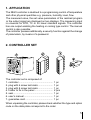
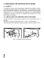
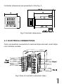
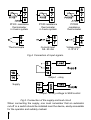
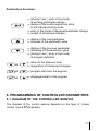
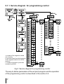
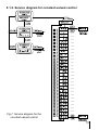
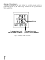
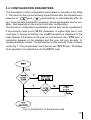
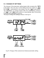
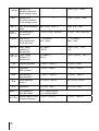
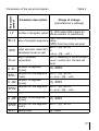
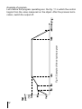
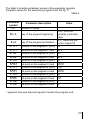
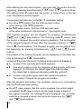
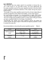
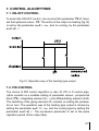
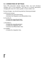
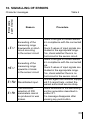
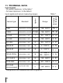
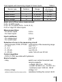
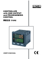
CONTROLLER with ONE OUTPUT and PROGRAMMING CONTROL RE23 TYPE USER'S MANUAL Contents: 1. Application..................................................................................5 2. Controller set..............................................................................5 3. Controller preparation to work..................................................6 3.1. Safety....................................................................................6 3.2. Controller installation in the panel.........................................6 3.3. Electrical connections............................................................9 3.4. Installation recommendations................................................9 4. Starting to work........................................................................10 5. Programming of controller parameters.......................................11 5.1.Diagram of the controller service.......................................... 11 5.1.1. Service diagram for the programming control.......................... 12 5.1.2. Service diagram for the constant valued control...................... 13 5.2. Configuration parameters....................................................15 5.3. Setting change.....................................................................16 5.4. List of configuration parameters..........................................17 5.5. Controller programming in the programmed work...............20 6.Input and output of the controller............................................25 6.1. Measuring input...................................................................25 6.2. Output..................................................................................26 7. Control algorythms .................................................................27 7.1. ON-OFF control...................................................................27 7.2. PID control...........................................................................27 8. Additional functions.................................................................28 8.1. Display of the control signal.................................................28 8.2. Manual control.....................................................................28 8.3. Control behaviour after sensor damage..............................29 8.4. Manufacturer’s settings.......................................................29 9. Selection of PID parameters settings.....................................30 9.1. AutomatIc choice of settings................................................30 9.2. Manual choice of settings ...................................................31 9.3. Correction of settings . ........................................................32 10. Signalling of errors................................................................33 11. Technical data.........................................................................34 12. Order codes............................................................................37 13. Maintenance and guarantee..................................................38 September 2007 - KZ 1351/07 1. APPLICATION The RE23 controller is destined to a programming control of temperature and other physical quantities e.g. pressure, humidity, level, flow. The measured value, the set value parameters of the realized program or the output signal are displayed on two displays. The measuring input is universal for RTD, TC or for linear standard signals. The controller has one output enabling the heating or cooling type control. The manual control is also possible. The controller possess additionally a security function against the change of parameters, by means of a password. 2. CONTROLLER SET The controller set is composed of: 1. controller.................................................... 2. plug with 6 screw terminals....................... 3. plug with 8 screw terminals....................... 4. holder to fix in the panel............................ 5. seal............................................................ 6. user’s manual............................................ 7. guarantee card.......................................... 1 pc 1 pc 1 pc 2 pcs 1 pc 1 pc 1 pc When unpacking the controller, please check whether the type and option code on the data plate correspond to the order. 3. PREPARING THE CONTROLLER TO WORK 3.1. Safety The RE23 controller fulfils requirements related to the safety of electrical measuring instruments for automatics acc. to the EN 61010-1 standard, requirements related to the resistance against electromagnetic interference acc. to the EN 61000-6-2 standard, and electromagnetic interference emission occurring in industrial environment acc. to the EN 61000-6-4 standard. 3.2. Installing the controller in the panel Fix the controller in the panel by means of two screw holders acc. to the fig.1. The hole in the panel should have 45+0,6 x 45+0,6 mm dimensions. The tickness of the material for panel execution cannot exceed 15 mm. Fig.1. Controller fixing in the panel. Controller dimensions are presented on the Fig. 2. Fig.2 Controller dimensions. 3.2. Electrical connections Carry out electrical connections to terminal strips and next, insert strips into controller sockets. Fig.3 View of controller connection strips. Pt100 resistance thermometer in 2-wire system Thermocouple Pt100 resistance thermometer in 3-wire system Pt1000 resistance thermometer Current input 0/4..20 mA Voltage input 0..5/10 V Fig.4. Connection of input signals . Output - relay Supply Output - binary voltage to SSR control Fig.5. Connection of the supply and load circuit When connecting the supply, one must remember that an automatic cut-off or a switch should be installed near the device, easily accessible for the operator and suitably marked. 3.4. INSTALLATION RECOMMENDATIONS The RE23 controller fulfils requirements concerning the fastness against electromagnetic interference occurring in the industrial environment acc. to obligatory standards. In order to obtain a full immunity of the controller against electromagnetic interference in an unknown environment interference level it is recommended to observe following principles: - do not supply the controller from the network near devices generating high impulse interference and do not use common earthing circuits with them. - apply network filters, - apply metallic shields in the shape of tubes or braided screens to conduct supplying wires, - wires supplying the measuring signal should be twisted in pairs, and for resistance thermometers in a 3-wire connection, twisted from wires of the same length, cross-section and resistance, and led in a shield as above, - all screens should be one side earthed, and led the nearest possible to the controller, - apply the general principle that wires leading different signals should be led the farthest possible between them (not less than 30 cm), and their crossing executed at a right angle. 4. STARTING TO WORK After the correct installation and connecting to the power, the controller carries out the display test, displays the controller type on the upper display and the program version on the lower display. Next, the measured value is displayed on the upper display or a message informing about abnormalities (table 6), and the set point of the controlled quantity on the lower display. The index 1 informs about the controller output state: ■ when lighting - output is switched on, ■ when blanking - output is switched off The index P informs about the programmed working mode of the controller: ■ when lighting, that the control is switched on acc. the program, ■ when flickering, that means the control has been disabled by the operator, but the program is not finished, ■ when blanking, that means the control is disabled because of the program. Termination or the controller has been programmed in the constant valued control mode. The index informs about the manual working mode of the control: ■ when lighting - the manual control is switched on, ■ when blanking - the automatic control is switched on 10 Push-button functions: • (during 2 sec. ) entry in the mode of working parameter change • display of the control signal and entry in the manual working mode • entry in the mode of displayed parameter change • accept of introduced changes • display of the next parameter • increase of the parameter value • display of the previous parameter • decrease of the parameter value • (during 2 sec. ) entry in the mode of program definition and • return to the previous level • resignation of introduced changes and • program start from the beginnin and • stoppage/restart of the program 5. PROGRAMMING OF CONTROLLER PARAMETERS 5.1. Diagram of the controller service The diagram of the control service depends on the type of chosen control (see tspparameter). 11 5.1.1. Service diagram for programming control n-number of the segment carried out currently t-time that flows from the beginning of the segment carried out -at the moment l-number of program cycles that remains to perform Fig.6. Service diagram for programming control The way to define parameters of the set point program and the operation of the programming control is described in the section 5.5. 12 5.1.2. Service diagram for constant-valued control Fig.7. Service diagram for the constant-valued control 13 Change of the set point The way to change the set point during the constant-valued control is presented on the Fig. 8. The change limitation is set by parameters SPLL and SPLH Fig.8. Change of the set point. 14 5.2. Configuration parameters The description of the configuration parameters is included in the table 1. The return to the normal working mode follows after the simultaneous pressure of and push-buttons or automatically after 30 sec. since the last push-button pressure. Some parameters can be invisible - that depends on the current controller configuration. The access to configuration parameters can be secured by a password. If the security code is set (seCU parameter is higher than zero), one must give it. During its setting, the codeinscription is displayed in the lower display. If the value is not given or is erroneous, the read only inscription appears on he displays and the user will only be able to review parameter values. The introduction of the security code is shown on the fig. 7. The programmer menu has its own seCpcode. Principles of its operation are identical as for theseCU code. Fig. 9. Introduction of the access code. 15 5.3. Change of settings The change of the parameter setting begins after pressing the push-button. One can carry out the setting choice by means of and push-buttons, and accept it by the push-button. The cancellation of change follows after the simultaneous pressure of and push-buttons or automatically after 30 seconds since the last push-button pressure. The way to change the setting is shown in the fig.10. Fig.10. Change of the numerical and textual parameter setting. 16 5.4. Liste of configuration parameters The list of configuration parameters is presented in the table 1. Parameter symbol List of parameters in the configuration menu Parameter description Table 1 Range of parameter change [manufacturer’s settings] sensors linear signals inpt kind of input (description in table 2) [pt1]: Pt100 pt10: Pt1000 t-,: thermocouple J t-t: thermocouple T t-k: thermocouple K t-s: thermocouple S t-r: thermocouple R t-b: thermocouple B t-e: thermocouple E t-n: thermocouple N t-l: thermocouple L t-lj type of line ( 2-wire or 3-wire line)1) [2-p]: 2-wire line 3-p: 3-wire line r-li 2-wire resistance line, [0.0]...20.0 for Pt100 sensor — C,C way of cold junction compensation for thermocouples 2) [auto]: automatic compensation Hand: manual compensation — C,Ct temperature of cold junctions at manual compensation [°C x10] 2) [0.0]...50.0 °C — reso position of the decimal point 0_dp: without decimal place [1_dp]: 1 decimal place [0-20]: lin. cur. 0-20 mA 4-20: lin. cur. 4-20 mA 0-5: lin. volt. 0-5 V 0-10: lin. volt. 0-10 V — 0_dp: without decimal place [1_dp]: 1 decimal place 2_dp: 2 decimal place 17 iNlo indication for the lower threshold of the analog output — -1999...[0.0] ...9999 3) iNHi indication for the upper threshold of the analog output — -1999...[100.0] ...9999 3) shjf shift of the measured -99.9...[0.0] ...99.9 °C value -999...[0.0] ...999 3) sPrr accretion rate of the set point 7) 0...[0.0] ...99.9 / time unit 0...[0.0] ...99.9 / time unit ramp time unit for the accretion rate of the set point 7) [min]: minute Hour: hour [min]: minute Hour: hour spll lower setting limitation of the set point acc. table 2 3) [-199.0] INLO...[0,0] ...INHI 3) [0.0] splH upper setting limitation of the set point acc. table 2 3) [850.0] INLO...[100.0] ...INHI 3) pb proportional band 0...[30.0] ...999.9 °C 0...[30.0]...9999 3) ti integration time-constant 4) 0...[300] ...9999 s 0...[300] ...9999 s td differentiation time-constant 4) 0...[60.0] ...999.9 s 0...[60.0] ...999.9 s to pulse repetition period 4) 0.5...[20.0] ...99.9 s 0.5...[20.0] ...99.9 s Hy hysteresis 5) 0.2...[2.0] ...99.9 0.2...[2.0] ...999 3) out1 configuration of the main output [dir]: cooling signal inu: heating signal o1.fn control signal In case 0...[0.0] ...100,0 % of sensor damage 4) 18 0...[0.0] ...100,0 % aTfn tsp seCU autotuning fonction 7) off: locked [ on]: unlocked kind of set point [con]: constant-valued control pr9: programming control safety code 6) [0]...9999 [0]...9999 Parameter only visible for the Pt100 sensor. Parameter only visible for TC. Resolution which the given parameter is shown with depends on the reso parameter - position of the decimal point. 4) Parameter only visible at proportional control (pb > 0). 5) Parameter visible only at on-off control (pb=0). 6) Parameter hidden in parameter reviewing mode only for readout (read only). 7) Parameter visible for the constant valued control. 1) 2) 3) 19 Measuring ranges for inputs Table 2 Symbol Input/sensor Minimum Maximum pt1 pt10 t-, t-t t-k t-s t-r t-b t-e t-n t-l 0-20 4-20 0-5 0-10 Resistance thermometer Pt100 Resistance thermometer Pt1000 Thermocouple of J type Thermocouple of T type Thermocouple of K type Thermocouple of S type Thermocouple of R type Thermocouple of B type Thermocouple of E type Thermocouple of N type Thermocouple of L type Linear current 0-20 mA Linear current 4-20 mA Linear voltage 0-5 V Linear voltage 0-10 V -199 °C -199 °C -100 °C -100 °C -100 °C 0 °C 0 °C 0 °C -100 °C -100 °C -199 °C -1999 -1999 -1999 -1999 850 °C 850 °C 1200 °C 400 °C 1372 °C 1767 °C 1767 °C 1820 °C 999 °C 1300 °C 800 °C 9999 9999 9999 9999 5.5. Controller programming in the programmed working mode The controller controls the object acc. to the set point changing in time in accordance with the assigned function, named the program. The program is composed maximally of 9 segments. For each segment, one must give the duration time and the 4 set point on the segment end. The segment time and the set point equals 0 mean the end of the program. Moreover, one must define: • the number of cycles, that is how many times the cycle is to be repeated, • the way of the program beginning: from the measured value or from the value defined in the next parameter, • the set point on the program beginning, • the controller behaviour after the program termination: switch the output off or continue acc. to the last set point. 20 Parameter symbol Parameters of the set point program lC strt sp0 end ti01 sp01 ti02 sp02 ti09 sp09 seCp Parameter description Table 3 Range of change [manufacturer’s settings] [1]...255 (value 255 means an infinite number of repetitions) pU0- from the currently controlled way of program beginning value [sp0]- from the initial set point spll...[0]...splH initial set point, when Strt or parameter is set on sp0 iNlo ...[0]...INHI way of program [off]- disabling of control output termination cont- control acc. the last set point duration of segment [0]...9999 1 [min] set point on the segment spll...[0]...splH 1 end or iNlo ...[0]...INHI duration of segment [0]...9999 2 [min] set point on the segment spll...[0]...splH 2 or iNlo ...[0]...INHI ...... duration of the segment [0]...9999 9 [min] set point on the segment spll...[0]...splH 9 end safety code [0]...9999 number of program cycles 21 Fig.11. Example of the set point program Example of program. Let’s define the program operating acc. the fig. 11 in which the control begins from the value measured on the object. After the process termination, switch the output off. 22 The table 4 includes parameter values in the exemplary program. Parametr values for the exemplary program from the fig. 11 Table 4 Parameter symbol lC strt 1) Parameter description number of cycles way of the program beginning end way of the program termination ti01 sp01 ti02 sp02 ti03 sp03 ti04 sp04 ti05 sp05 ti06 sp06 duration of the segment 1 [min] set point on the segment 1 end duration of the segment 2 [min] set point on the segment 2 end duration of the segment 3 [min] set point on the segment 3 end duration of the segment 4 [min] Value 1 pU0 - from the currently controlled value off- switching the control output off 30 50.0 30 80.0 60 120.0 240 duration of the segment 5 [min] 120.0 60 set point on the segment 5 end 0.0 duration of the segment 6 [min] 01) set point on the segment 6 end 01) set point on the segment 4 end segment time and set point equals 0 means the program end. 23 After defining the set point program, one must start the control from the beginning, pressing simultaneously and push-buttons. The lighting index P means that the control is realized acc. to the set point calculated from the program. The program will start acc. to the Strt parameter setting: ■ the value sp0 means, that the initial set point value is the setting of the sp0 parameter, ■ the pU0 value means, that the initial set point value is the value measured in the moment of the program start. The realized program can be stopped by pressing simultaneously and push-buttons. The flickering index P means, that the control is stopped (the control output is disabled). The continuation of the stopped program follows after the renewed pressing of and push-buttons. The stopped program can be started from the beginning by pressing simultaneously and push- buttons. Parameters of the realized program can be displayed on the lower display by pressing the push-button. Instead of the current set point, following parameters are displayed: ■ n - number of the currently performed segment, ■ t - time which elapses since the beginning of the actually performed segment [in minutes]. For times higher than 999 minutes, the oldest digit is displayed alternately with the symbol t ■ l - number of program cycles which still remains to perform. The number 0 means the program termination. After the program termination, the controller carries on in accordance with the End parameter setting: ■ the off value means, that the control is ended, the control output is disabled, the P index is blank. On the lower display instead of the segment number the message End is displayed. The controller waits for a renewed program start since the beginning, by and push-buttons. 24 ■ the cont value means, that the control is continued acc. to the last set point in the program without the time count down. The P index is still lighting, the number of cycles to do is equal 0. On the lower display instead of the segment number, the message cont is displayed. The control can be disabled by a simultaneous pressure of and , push-buttons, or restart the program from the beginning by and push-buttons. 6. INPUT AND OUTPUT OF THE CONTROLLER 6.1. measuring input The controller has one measuring input, which one can connect different types of sensors or standard signals to. The choice of the input signal is carried out by the inpt parameter. For different types of inputs, depending on the option code, one must give additional parameters. For the Pt100 resistance thermometer, one must choose the kind of connection. In a three-wire connection, the line resistance compensation goes on automatically. In a two-wire connection, one can give additionally the line resistance. For thermocouples, one must give the way of temperature compensation of cold ends - automatic or manual, and at manual compensation - the temperature of cold ends. For linear inputs, one must give the indication for the lower and upper threshold of the analog input. The additional parameter is the number of digits after the decimal point, the rEso parameter. For temperature sensors, it defines whether the measured temperature and the set point temperature is to be shown with a place after the decimal point. For linear inputs, it defines the resolution which the measured value and values of some parameters are shown with. The correction of the measured value indications is carried out by the shif parameter. 25 6.2. OUTPUT The controller has one output, which it is possible to choose the onoff or PID control in. For the PIDl control, one must additionally set the pulse repetition period.The pulse repetition period is the time which expires between successive switches of the output during the proportional control. The length of the pulse repetition period must be chosen depending on dynamic properties of the object and suitably to the output device For quick-acting processes, it is recommended to apply SSR relays. The relay output is used to control contactors in slow-acting processes. The use of a high pulse repetition period to control quick-acting processes can give unwanted effects in the shape of oscillations. Theoretically, the smaller the pulse repetition period, the better the control, but for the relay output, it should be as high as possible in order to extend the relay life. Recommendations concerning the pulse repetition period Output electromagnetic relay transistor output 26 Pulse repetition period to recommended >20s (min. 10 s) min. 5 s 1...3 s Table 5 Load 2A/230 V a.c. or contactor 1A/230V a.c. semi-conductor relay (SSR) 7. CONTROL ALGORYTHMS 7.1. ON-OFF CONTROL To select the ON-OFF control, one must set the parameter pb=0. Next, set the hysteresis value - Hy. The action of the output on heating (fig.12) is set by the parameter out=inu, and on cooling, by the parameter out=dir. Fig.12. Operation way of the heating type output. 7.2. PID CONTROL The choice of PID control algorithm or also PI, PD or P control algorythm consists on a suitable setting of parameter values - proportional band (pb), integrating element (ti) and differentiating element (td). The switching of the giving element off, consists on setting the parameter on zero. The operation way of the heating type output is chosen by setting the parameter out1=inu, and the cooling type by setting the parameter out=dir. The successive parameter to set is the pulse repetition period of the output (to). 27 8. ADDITIONAL FUNCTIONS 8.1. DISPLAY OF THE CONTROL SIGNAL After pressing the push-button, the value of the control signal (0...100%) appears on the display. On the first digit, the mark h is displayed. The return to the normal operation follows after the double push-button. pressure of the 8.2. MANUAL CONTROL The manual control gives the possibility, among other things, to identify and test the object or control it after the sensor damage. The entry into the manual control mode follows after holding down the push-button when displaying the control signal. The manual control is signaled by the pulsation of the measured value. The controller breaks the automatic control and begins the manual control of the output. The value of the control signal is displayed on the lower display, preceded by the symbol h. and push-buttons serve to change the control signal. The exit to the normal working mode follows after the simultaneous pressure of and push-buttons. After setting the ON-OFF control on the output (parameter pb = 0), one can set the control signal on 0% or 100% of power, however when the Pb parameter is greater than zero, the control signal can be set on any value from the 0...100% range. 28 8.3. controller behaviour after the sensor damage It is possible to configure the output state after the sensor damage: ■ at output configuration for proportional control (pb>0) the control signal value is defined by the oIflparameter, at output configuration for the ON-OFF control (pb=0), the output ■ will be disabled, at output operation as heating, or enabled - at output operation as cooling. 8.4. Manufacturer’s settings One can restore manufacturer’s settings, during the supply switching on, holding and push-buttons till the moment when the inscription fabr appears in the upper display. 29 9. selection of PID parameter settings 9.1. Automatic choice of settings The controller has the function of the automatic PID setting selection. These settings ensure in the most of cases the optimal control. To begin the autotuning, one must transit to the tune position (acc. to the fig.7) and hold the push buton during at least 2 sec. If the proportional band is equal zero or the aTfn parameter is set on off or the tsp parameter is set on pr9 then it will not be possible to begin the autotuning. The flickering upper display informs about the activity of the autotuning function. The autotuning duration depends on the dynamic properties of the object and can last maximally 10 hours. During the autoadaptation or directly after it, overshoots can appear and for this reason, one must set a lower set point, if it is possible. After the autotuning termination, calculated PID settings are stored in the non-volatile memory and the process control with new settings begins. The autotuning process may not begin or be broken without the calculation of PID settings, if: – the control deviation is lower than 6.5 % of the range (splH-spll) – the time of the object preliminary stabilization or the admissible autotuning duration will be exceeded, – a decay of the controller supply occurs, – the push-button has been pressed, – calculated parameter values are beyond the range. In such cases the control with previous PID settings will begin. 30 Fig.13. Selection of settings by the method of response to a unitary jump. 9.2. manual selection of settings Set the on-off control with a minimal hysteresis. Set the set point as to we can observe the run of the measured value as in the fig.13. One must read out the delay time To and the maximal temperature accretion rate from the object characteristic presenting the controlled value in the function of time, from the dependence: Vmax = ∆PV max ∆t Calculate PID settings acc. to following formulas: Pb = 1.1 • Vmax • T0 - proportional band ti = 2.4 • T0 - integration time constant td = 0.4 • T0 - differentiation time constant 31 9.3. correction of settings Since PID parameters interact between them, one must introduce changes only of one parameter. The best is to choose parameters changing the value into a twice greater or twice smaller one. During changes, one should be guided by following principles: a) Slow jump answer: – decrease the proportional band, – decrease the integration and differentiation time. b) Overshoots: – increase the proportional band, – increase the differentiation time. c) Oscillations: – increase the proportional band, – increase the integration time, – decrease the differentiation time. d) Instability: – increase the integration time. 32 10. signalling of errors Error code (upper display) Character messages Reason lerr Exceeding of the measuring range downwards or shortcircuit occurring in the sensor circuit. Herr Exceeding of the measuring range upwards or break in the sensor circuit. eRad Discalibrated input. eRat The automatic selection of PID parameters cannot be produced or was broken. Table 6 Procedure Check if the type of chosen sensor is in compliance with the connected one. Check if values of input signals are situated in the appropriate range. If so, check whether there is no short-circuit in the sensor circuit. Check if the type of chosen sensor is in compliance with the connected one. Check if values of input signals are situated in the appropriate range. If so, check whether there is no short-circuit in the sensor circuit. Connect again the controller supply and if it cannot help, contact the nearest authorized service shop. Check conditions of the autotuning function generation described in section 9.1. The message disappears after pressing any push-button. 33 11. technical data Input signals: - for sensor inputs acc. to the table 7 - for linear inputs acc. to the table 8 Range Symbol on the display Table 7 Symbol Input signals and sensor measuring ranges Pt100 -199...850°C pt1 Pt1000 -199...850°C pt10 PN-EN 60584-1:1997 J -100...1200°C t-, Cu-CuNi PN-EN 60584-1:1997 T -100...400°C t-t NiCr-NiAl PN-EN 60584-1:1997 K -100...1372°C t-k PtRh10-Pt PN-EN 60584-1:1997 S 0...1767°C t-s PtRh13-Pt PN-EN 60584-1:1997 R 0...1767°C t-r PtRh30-PtRh6 PN-EN 60584-1:1997 B 0...1820°C 300...1820°C 1) t-b NiCr-CuNi E PN-EN 60584-1:1997 E -100...999°C t-e NiCrSi-NiSi PN-EN 60584-1:1997 N -100...1300°C t-n NiCr-CuNi (chromel-kopel) Gost R 8.585- 2001 L -100...800°C t-l Sensor type Standard Pt100 PN-EN 60751+A2:1997 Pt1000 PN-EN 60751+A2:1997 Fe-CuNi 1) Range which the measurement error is given to 34 Input signals and measuring ranges for linear inputs Sensor type Notation Range Linear current I 0...20 mA Linear current I 4...20 mA Linear voltage U 0...5 V Linear voltage U 0...10 V Table 8 Symbol on the display 0-20 4-20 0-5 0-10 Basic error of true value measurement: 0.2%, for RTD inputs, 0.3%, for TC inputs (0.5% - for B, R, S); 0.2% ±1 digit, for linear inputs Measurement time: - for sensor inputs - for linear inputs 0.33 s 0.16 s Input resistance: - for voltage input - for current input 150 kΩ 4Ω Detection of error in the measuring circuit: - thermocouple, Pt100, PT1000 overrunning of the measuring range - 0...10 V over 11 V - 0...5 V over 5,25 V - 0...20 mA over 22 mA - 4...20 mA under 1mA nd over 22 mA Control algorithm: - P,PD, PI, PID, two-state with hysteresis Kind of outputs: - relay - binary voltage (without isolation from the sensor side) switch over contact maximal load- carrying capacity: - voltage: 250 V a.c., 150 V d.c. - current: 5A 250 V a.c., 5 A 30 V d.c. - resistance load: 1250 VA, 150 W voltage: 5 V resistance limiting the current: 66 Ω 35 Way of output action: - reverse - direct for heating for cooling Signalling of the: - output switching on - programming control - manual control mode Rated service conditions: - supply voltage - supply voltage frequency - ambient temperature - storage temperature - relative air humidity - external magnetic field - preheating time - work position - resistance of wires connecting the resistance thermometer with the controller 230 V a.c. ±10% 110 V a.c. ±10% 24 V a.c. ±10% 50...60 Hz 0...23...50 °C -20...+70 °C < 85 % (without condensation) < 400 A/m 30 min any <20 Ω Power consumption < 3 VA Weight < 0.25 kg IP protection ensured through the housing: acc. to EN 60529 - from the frontal side - from terminal side IP65 IP20 Additional errors in rated working conditionscaused by: - compensation of the thermocouple cold junction ≤ 2°C, - ambient temperature change ≤ 100% of the basic error value /10K. Safety requirements acc. to EN 61010-1 - installation category III, - level of pollution 2, - maximal working voltage in relation to ground: - for supply circuit, outputs - 300 V a.c. - for input circuits - 50 V a.c. 36 Electromagnetic compatibility - immunity acc. to EN 61000-6-2 - emission acc. to EN 61000-6-4 12. order codes Coding way is given in the table 9. Kind of options and ordering way Controller RE23 - Table 9 X X X X Input: universal for thermocouples and RTD...... 1 universal linear current: 0/4...20 mA, linear voltage: 0...5/10 V ......................... 2 on order . ................................................. X Output: relay................................................................ 1 binary 0/5V to SSR control.............................. 2 on order...........................................................X Supply: 230 V 50/60 Hz..................................................... 1 110 V 50/60 Hz...................................................... 2 24 V 50/60 Hz....................................................... 3 on order................................................................. X Additional requirements without an extra quality inspection certificate...............8 with an extra quality inspection certificate....................7 acc. to customer’s agreement*.................................... X * The option code is established by the manufacturer. Ordering example: The code: RE23-1-2-3-7 means RE23 - controller with universal input + 1 output 1 - universal input for RTD and TC 2 - binary output 0/5 V to SSR control 3 - supply: 24 V a.c. 7 - with an extra quality inspection certificate 37 13. MAINTENANCE AND GUARANTEE The RE23 controller does not require any periodical maintenance. In case of some incorrect operations: 1. After the dispatch date and in the period stated in the guarantee card One should return the instrument to the Manufacturer’s Quality Inspection Dept. If the instrument has been used in compliance with the instructions, the Manufacturer warrants to repair it free of charge. The disassembling of the housing causes the cancellation of the granted guarantee. 2. After the guarantee period: One should turn over the instrument to repair it in a certified service workshop. Spare parts are available for the period of five years from the date of purchase. We reserves the right to make changes in design and specifications of any products as engineering advances or necessity requires. 38 39 SALES PROGRAMME MEASUREMENT DIGITAL and BARGRAPH PANEL METERS CONTROL MEASURING TRANSDUCERS RECORDING ANALOG PANEL METERS (DIN INSTRUMENTS) ANALOG and DIGITAL CLAMP-ON METERS PROCESS and HOUSEHOLD CONTROLLERS CHART AND PAPERLESS RECORDERS POWER CONTROL UNITS and SOLID-STATE RELAYS AUTOMOTIVE DASHBOARD INDICATORS 1-PHASE AND 3-PHASE WATT-HOUR METERS NUMERICAL AND ALPHANUMERICAL LARGE SIZE DISPLAYS ACCESSORIES FOR MEASURING INSTRUMENTS (SHUNTS AND MODULES) MEASURING SYSTEMS (ENERGY, HEAT, CONTROL) CUSTOM-MADE ELECTRONIC SUBASSEMBLIES ACC. TO ORDERS WE ALSO OFFER OUR SERVICES IN THE PRODUCTION OF: ALUMINIUM ALLOY PRESSURE CASTINGS PRECISION ENGINEERING AND THERMOPLASTICS PARTS PRESSURE CASTING DIES AND OTHER TOOLS CUSTOM-MADE ELECTRONIC SUB-ASSEMBLIES QUALITY PROCEDURES: According ISO 9001 and ISO 14001 international requirements. All our instruments have CE mark. For more information, please write to or phone our Export Department. Lubuskie Zak³ady Aparatów Elektrycznych LUMEL S.A. ul. Sulechowska 1 65-022 Zielona Góra - Poland tel.: (48-68) 329 51 00 (exchange) fax: (48-68) 329 51 01 e-mail: [email protected] http://www.lumel.com.pl 40 Export Department: Tel.: (48-68) 329 53 02 or 53 04 Fax: (48-68) 325 40 91 e-mail: [email protected]