1
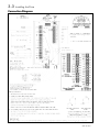
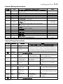
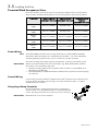
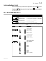
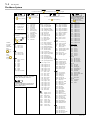
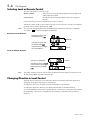
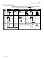
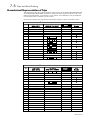
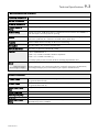
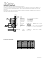
3-5 Installing the Drive
Terminal Block Acceptance Sizes
Wire sizes should be chosen with respect to the operating conditions and your local National
Electrical Safety Installation Requirements. Local wiring regulations always take precedence.
Frame Size
Frame 1
230V
Frame 2
230V
Frame 2
400V
Frame 3
230V
Frame 3
400V
Power Terminals
(maximum wire size)
Brake Terminals
(maximum wire size)
Thermistor/Control
Terminals
(maximum wire size)
2.5mm2/12 AWG
Not Applicable
2.5mm2/12 AWG
2.5mm2/12 AWG
Not Applicable
2.5mm2/12 AWG
2.5mm2/12 AWG
2.5mm2/12 AWG
2.5mm2/12 AWG
6.0mm2/10 AWG
6.0mm2/10 AWG
2.5mm2/12 AWG
6.0mm2/10 AWG
6.0mm2/10 AWG
2.5mm2/12 AWG
Power Wiring
Note:
For specified EMC emission and immunity performance, install to EMC Installation
Instructions. Refer to Chapter 10: “Certification for the Drive” - for more information
Terminal tightening torque for Frame 3 power connections is 20 lb.in (2.26Nm).
Protect the incoming mains supply using the specified fuse, or RCD circuit breaker Type B.
IMPORTANT: We do not recommend the use of circuit breakers (e.g. RCD, ELCB, GFCI), however,
where their use is mandatory, they must:
•
•
Control Wiring
Operate correctly with dc and ac protective earth currents (i.e. type B RCDs as in
Amendment 2 of IEC755).
Have adjustable trip amplitude and time characteristics to prevent nuisance tripping
on switch-on.
Control wiring of between 0.08mm2 (28AWG) and 2.5mm2 (12AWG) can be used. Ensure all
wiring is rated for the highest system voltage. All control terminals are SELV, i.e. doubleinsulated from power circuits.
Using Cage Clamp Terminals
Strip wire insulation to 5-6mm (0.20-0.24 inches), or alternatively
use wire-crimps. Use a flat-bladed screwdriver, maximum blade size
3.5mm. The cage provides the correct force for a secure connection.
IMPORTANT: DO NOT lever or turn the screwdriver.
650V AC Drive


![[AC10] : HA502320U001 : Product Manual to support the Parker](http://vs1.manualzilla.com/store/data/006162733_1-f6c7f4023b54f3efd3a5308c67bef951-150x150.png)