1
650V Frame 1, 2 & 3 HA467649U003 Issue 2 Product Manual aerospace climate control electromechanical filtration fluid & gas handling hydraulics pneumatics process control sealing & shielding 650V AC Drive Frame 1, 2 & 3 Product Manual HA467649U003 Issue 2 Compatible with Version 5.x Software onwards 2013 Parker Hannifin Manufacturing Ltd. All rights strictly reserved. No part of this document may be stored in a retrieval system, or transmitted in any form or by any means to persons not employed by a Parker SSD Drives company without written permission from Parker SSD Drives, a division of Parker Hannifin Ltd . Although every effort has been taken to ensure the accuracy of this document it may be necessary, without notice, to make amendments or correct omissions. Parker SSD Drives cannot accept responsibility for damage, injury, or expenses resulting therefrom. WARRANTY The general terms and conditions of sale of goods and/or services of Parker Hannifin Europe Sarl, Luxembourg, Switzerland Branch, Etoy, apply to this product unless otherwise agreed. The terms and conditions are available on our website www.parker.com/terms andconditions/switzerland FAILURE OR IMPROPER SELECTION OR IMPROPER USE OF THE PRODUCTS DESCRIBED HEREIN OR RELATED ITEMS CAN CAUSE DEATH, PERSONAL INJURY AND PROPERTY DAMAGE. This document and other information from Parker-Hannifin Corporation, its subsidiaries and authorized distributors provide product or system options for further investigation by users having technical expertise. The user, through its own analysis and testing, is solely responsible for making the final selection of the system and components and assuring that all performance, endurance, maintenance, safety and warning requirements of the application are met. The user must analyze all aspects of the application, follow applicable industry standards, and follow the information concerning the product in the current product catalog and in any other materials provided from Parker or its subsidiaries or authorized distributors. To the extent that Parker or its subsidiaries or authorized distributors provide component or system options based upon data or specifications provided by the user, the user is responsible for determining that such data and specifications are suitable and sufficient for all applications and reasonably foreseeable uses of the components or systems. Cont.2 ! Safety Information Requirements IMPORTANT: Please read this information BEFORE installing the equipment. Intended Users This manual is to be made available to all persons who are required to install, configure or service equipment described herein, or any other associated operation. The information given is intended to highlight safety issues, EMC considerations, and to enable the user to obtain maximum benefit from the equipment. Complete the following table for future reference detailing how the unit is to be installed and used. INSTALLATION DETAILS Model Number (see product label) Where installed (for your own information) Unit used as a: (refer to Certification for the Inverter) Component Relevant Apparatus Unit fitted: Wall-mounted Enclosure Application Area The equipment described is intended for industrial motor speed control utilising DC motors, AC induction or AC synchronous machines Personnel Installation, operation and maintenance of the equipment should be carried out by qualified personnel. A qualified person is someone who is technically competent and familiar with all safety information and established safety practices; with the installation process, operation and maintenance of this equipment; and with all the hazards involved. Product Warnings Caution Risk of electric shock Caution Refer to documentation Earth/Ground Protective Conductor Terminal Cont.3 ! Safety Information Hazards DANGER! - Ignoring the following may result in injury 1. This equipment can endanger life by exposure to 5. For measurements use only a meter to IEC 61010 rotating machinery and high voltages. (CAT III or higher). Always begin using the highest range. 2. The equipment must be permanently earthed due to the CAT I and CAT II meters must not be used on this high earth leakage current, and the drive motor must be product. connected to an appropriate safety earth. 6. Allow at least 5 minutes for the drive's capacitors to 3. Ensure all incoming supplies are isolated before discharge to safe voltage levels (<50V). Use the working on the equipment. Be aware that there may be specified meter capable of measuring up to 1000V more than one supply connection to the drive. dc & ac rms to confirm that less than 50V is present between all power terminals and earth. 4. There may still be dangerous voltages present at power 7. Unless otherwise stated, this product must NOT be terminals (motor output, supply input phases, DC bus dismantled. In the event of a fault the drive must be and the brake, where fitted) when the motor is at returned. Refer to "Routine Maintenance and standstill or is stopped. Repair". WARNING! - Ignoring the following may result in injury or damage to equipment SAFETY Where there is conflict between EMC and Safety requirements, personnel safety shall always take precedence. • Never perform high voltage resistance checks on the wiring without first disconnecting the drive from the circuit being tested. • Whilst ensuring ventilation is sufficient, provide guarding and /or additional safety systems to prevent injury or damage to equipment. • When replacing a drive in an application and before returning to use, it is essential that all user defined parameters for the product’s operation are correctly installed. • All control and signal terminals are SELV, i.e. protected by double insulation. Ensure all external wiring is rated for the highest system voltage. • Thermal sensors contained within the motor must have at least basic insulation. • All exposed metalwork in the Inverter is protected by basic insulation and bonded to a safety earth. • RCDs are not recommended for use with this product but, where their use is mandatory, only Type B RCDs should be used. EMC • In a domestic environment this product may cause radio interference in which case supplementary mitigation measures may be required. • This equipment contains electrostatic discharge (ESD) sensitive parts. Observe static control precautions when handling, installing and servicing this product. • This is a product of the restricted sales distribution class according to IEC 61800-3. It is designated as “professional equipment” as defined in EN61000-3-2. Permission of the supply authority shall be obtained before connection to the low voltage supply. CAUTION! APPLICATION RISK • The specifications, processes and circuitry described herein are for guidance only and may need to be adapted to the user’s specific application. We can not guarantee the suitability of the equipment described in this Manual for individual applications. RISK ASSESSMENT Under fault conditions, power loss or unintended operating conditions, the drive may not operate as intended. In particular: • Stored energy might not discharge to safe levels as quickly as suggested, and can still be present even though the drive appears to be switched off • The motor's direction of rotation might not be controlled • The motor speed might not be controlled • The motor might be energised A drive is a component within a drive system that may influence its operation or effects under a fault condition. Consideration must be given to: • Stored energy Cont.4 • Supply disconnects • Sequencing logic • Unintended operation Contents Contents CHAPTER 1 GETTING STARTED Page 1-1 Introduction .................................................................................................. 1-1 Equipment Inspection .............................................................................................. 1-1 Storage and Packaging ........................................................................................... 1-1 About this Manual ........................................................................................ 1-1 CHAPTER 2 AN OVERVIEW OF THE DRIVE 2-1 Component Identification ............................................................................. 2-1 CHAPTER 3 INSTALLING THE DRIVE 3-1 Mechanical Installation ................................................................................ 3-1 Mounting the Drive.................................................................................................. 3-1 Ventilation .............................................................................................................. 3-1 Electrical Installation .................................................................................... 3-2 Wiring Instructions................................................................................................... 3-2 Connection Diagram ............................................................................................... 3-3 Optional Equipment ..................................................................................... 3-6 CHAPTER 4 OPERATING THE DRIVE 4-1 Pre-Operation Checks .................................................................................. 4-1 Initial Start-up Routines ............................................................................... 4-1 Local Control Operation .......................................................................................... 4-2 Remote Control Operation ...................................................................................... 4-2 Set-up as an Open-loop drive (V/F Mode) ................................................................ 4-3 Set-up using the Sensorless Vector Mode .................................................................. 4-3 Tuning the Drive to Your System............................................................................... 4-5 CHAPTER 5 THE KEYPAD 5-1 Controlling the Drive using the Keypad ....................................................... 5-1 Control Key Definitions ............................................................................................ 5-1 Display Indications .................................................................................................. 5-2 Drive Status Indications............................................................................................ 5-2 Quick Application Selection ..................................................................................... 5-2 Selecting the Menu Detail ........................................................................................ 5-3 The DIAGNOSTICS Menu .............................................................................. 5-3 The Menu System .......................................................................................... 5-4 Special Menu Features.................................................................................. 5-5 How To Change a Parameter Value ......................................................................... 5-5 Resetting to Factory Defaults (2-button reset)............................................................. 5-5 Changing the Default Operating Frequency ............................................................. 5-5 Selecting Local or Remote Control ............................................................................ 5-6 Cont.5 Contents Contents Page Changing Direction in Local Control ........................................................................ 5-6 Password Protection ................................................................................................ 5-7 CHAPTER 6 PROGRAMMING YOUR APPLICATION 6-1 MMI Parameters ........................................................................................... 6-1 Product-Related Default Values .............................................................................. 6-16 CHAPTER 7 TRIPS AND FAULT FINDING 7-1 Trips .............................................................................................................. 7-1 Trip Warning Message ............................................................................................ 7-1 What Happens when a Trip Occurs .......................................................................... 7-1 Resetting a Trip Condition........................................................................................ 7-1 Using the Keypad to Manage Trips........................................................................... 7-1 Hexadecimal Representation of Trips ........................................................................ 7-5 Fault Finding ................................................................................................. 7-6 CHAPTER 8 ROUTINE MAINTENANCE & REPAIR 8-1 Routine Maintenance .................................................................................... 8-1 Repair ........................................................................................................... 8-1 Saving Your Application Data .................................................................................. 8-1 Returning the Unit to Parker SSD Drives .................................................................... 8-1 Disposal ................................................................................................................. 8-1 CHAPTER 9 TECHNICAL SPECIFICATIONS 9-1 Understanding the Product Code ............................................................................. 9-1 Environmental Details .............................................................................................. 9-3 Power Details .......................................................................................................... 9-3 Electrical Ratings ..................................................................................................... 9-4 Supply Short Circuit Rating....................................................................................... 9-5 User Relay .............................................................................................................. 9-5 Analog Inputs/Outputs ............................................................................................ 9-5 Analog Outputs ...................................................................................................... 9-5 Digital Inputs .......................................................................................................... 9-6 Digital Outputs ....................................................................................................... 9-6 Cabling Requirements for EMC Compliance ............................................................. 9-6 Internal Dynamic Braking Circuit .............................................................................. 9-7 External Brake Resistor............................................................................................. 9-7 Supply Harmonic Analysis (230V filtered) ................................................................ 9-8 Supply Harmonic Analysis (400V filtered) ................................................................ 9-9 Supply Harmonic Analysis (230V unfiltered) ........................................................... 9-10 Supply Harmonic Analysis (400V unfiltered) ........................................................... 9-11 CHAPTER 10 CERTIFICATION FOR THE DRIVE 10-1 Requirements for EMC Compliance............................................................. 10-1 Earthing Requirements ........................................................................................... 10-1 Requirements for UL Compliance ............................................................... 10-1 Cont.6 Contents Contents Page European Directives and the CE Mark ........................................................ 10-3 CE Marking for Low Voltage Directive .................................................................... 10-3 CE Marking for EMC - Who is Responsible?............................................................ 10-3 EMC Compliance ......................................................................................... 10-3 Certificates............................................................................................................ 10-4 CHAPTER 10 CERTIFICATION FOR THE DRIVE 10-1 Requirements for EMC Compliance............................................................. 10-1 Earthing Requirements ........................................................................................... 10-1 Requirements for UL Compliance ............................................................... 10-1 European Directives and the CE Mark ........................................................ 10-3 CE Marking for Low Voltage Directive .................................................................... 10-3 CE Marking for EMC - Who is Responsible?............................................................ 10-3 EMC Compliance ......................................................................................... 10-3 Certificates............................................................................................................ 10-4 CHAPTER 11 SERIAL COMMUNICATIONS 11-1 Connection to the P3 Port ........................................................................... 11-1 CHAPTER 12 APPLICATIONS 12-1 The Default Application .............................................................................. 12-1 How to Load an Application ....................................................................... 12-1 Application Description .............................................................................. 12-1 Control Wiring for Applications .............................................................................. 12-1 Application 1 : Basic Speed Control (default) .......................................................... 12-2 Application 2 : Auto/Manual Control ..................................................................... 12-4 Application 3 : Preset Speeds ................................................................................ 12-6 Application 4 : Raise/Lower Trim............................................................................ 12-8 Application 5 : PID .............................................................................................. 12-10 Application 6 : Auxilliary Comms ......................................................................... 12-12 Cont.7 Getting Started 1-1 Chapter 1 GETTING STARTED Introduction The 650V Series AC Drive provides simple, compact, and low-cost speed control for 3-phase induction motors This manual describes the low-power end of the 650V product range for the following motor power ratings: Frame 1 Frame 2 Frame 2 Frame 3 Frame 3 Frame 3 Nominal Input Voltage 230V 230V 400V 230V 230V 400V Phase 1 1 3 1 3 3 Drive Power 0.25 – 0.75kW 1.1 – 1.5kW 0.37 – 2.2kW 2.2kW 2.2 - 4.0 kW 3.0 – 7.5kW 0.3 1.5 0.5 3.0 3.0 4.0 - 1.0 Hp - 2.0 Hp - 3.0 Hp Hp - 5.0 Hp - 10.0 Hp The drive features: • Local or Remote mode operation • SELV control terminals (Safe Extra Low Volts) • Intelligent monitoring strategy to avoid nuisance tripping • In-built protection of the unit against overloads, excessive voltages, phase-to-phase and phase-to-earth short circuits • An internal RFI filter is fitted as standard • An internal dynamic brake switch for connection to an external resistor (Frame 3: 230V, and 400V units only) • Quiet operation • Controlling the unit locally using the 6511 Keypad gives access to parameters, diagnostic messages, trip settings and full application programming a connection to a pc is required along with the drive software tool. Other features also become available, such as the advanced sensorless vector control scheme which gives high torque, low speed operation; selectable switching frequencies; and a unique Quiet Pattern control system that minimises audible noise from the motor. Note: Do not attempt to control motors whose rated current is less than 50% of the drive rated current. Poor motor control or Autotune problems may occur if you do Equipment Inspection • Check for signs of transit damage • Check the drive is suitable for your requirements by reading the Product Code on the rating label. Refer to Chapter 9: “Technical Specifications” - Understanding the Product Code. If the unit is damaged, refer to Chapter 8: “Routine Maintenance and Repair” for information on returning damaged goods. Storage and Packaging Save the packaging in case of return. Improper packaging can result in transit damage. If the unit is not being installed immediately, store the unit in a well-ventilated place away from high temperatures, humidity, dust or metal particles. About this Manual This manual is intended for use by the installer, user and programmer of the drive. It assumes a reasonable level of understanding in these three disciplines. Note: Please read all Safety Information before proceeding with the installation and operation of this unit. It is important that you pass the manual on to any new user of this unit. 650V AC Drive 1-2 Getting Started Software Product Manual An accompanying Software Product Manual is available for download from the Parker SSD Drives website: www.parker.com/SSD 650V AC Drive An Overview of the Drive 2-1 Chapter 2 AN OVERVIEW OF THE DRIVE Component Identification 3 1 2 9 Frame 3 Frame 2 Frame 1 12 8 10 11 5 6 7 4 Figure 2-1 View of Component Parts (Frame 1 illustrated) 1 2 3 4 5 6 Main drive assembly Keypad DIN clip/fixing bracket Terminal cover Power terminals Motor cable screen clamp 650V AC Drive 7 8 9 10 11 12 Control terminals Volt-free relay contacts Product rating label Motor thermistor terminals RS232 programming port - P3 Encoder/digital inputs 3-1 Installing the Drive Chapter 3 INSTALLING THE DRIVE IMPORTANT: Read Chapter 10: “Certification for the Drive” before installing this unit. Mechanical Installation W The DIN clip is repositioned on Frames 1 and 2 to provide the upper fixing hole when wall-mounting W H3 DIN centreline C H4 H3 DIN centreline H1 H2 H1 H2 W D SIDE VIEW - Frame 1 illustrated Frame 1 Frame 2 Frame 3 C DIN centreline H4 W 2 2 REAR VIEW - Frame 3 REAR VIEW - Frame 1 illustrated (Frame 2 similar) Fixing Torque Weight H1 Fixing Centres H2 H3 H4 C W D M4 1.5Nm 0.85kg 132 143 35 139 6 73 142 (2 lbs) (5.2”) (5.6”) (1.4”) (5.5”) (0.2”) (2.9”) (5.6”) 1.4kg 188 201 35 194 6.5 73 173 (3 lbs) (7.4”) (7.9”) (1.4”) (7.7”) (0.24”) (2.9”) (6.8”) 2.7kg 242 260 38 112 5 96 200 (6 lbs) (9.5”) (10.2”) (1.5”) (4.4”) (0.2”) (3.8”) (7.9”) M5 M5 3.0Nm 3.0Nm Dimensions are in millimetres ( inches ) Mounting the Drive To maintain compliance with European Electrical Safety Standard VDE0160(1994)/EN50178 (1998) the unit must be mounted inside a control cubicle that requires a tool for opening. The cubicle should provide 15dB attenuation to radiated emissions between 30-100MHz. Mount the drive vertically on a solid, flat, non-flammable, vertical surface. It can be panel-mounted, or rail-mounted on a rail complying with EN50022 (35mm DIN). DIN Mounting To DIN mount the unit, hang the unit on the top DIN rail and push the unit onto the bottom DIN rail until it snaps in to position. Secure with a lower screw fixing. To release the unit, use a flat bladed screwdriver as shown. lower fixing hole Ventilation Maintain a minimum air clearance for ventilation of 100mm (4 inches) above and below the unit. When mounting two or more 650V units together, these clearances are additive. Ensure that the mounting surface is normally cool. Be aware that adjacent equipment may generate heat and also have clearance requirements. Provided the minimum clearance for ventilation is maintained, 650V drives may be mounted side-by-side. 650V AC Drive Installing the Drive 3-2 Electrical Installation IMPORTANT: Read the Safety Information on page Cont. 2 before proceeding. Wiring Instructions Local Control Wiring This is the simplest installation. Every new drive will operate in Local Control when first powered-up. The keypad is used to start and stop the drive. Minimum Connections Refer to the Connection Diagram and install the: Thermistor cable, or link/jumper terminals TH1A and TH1B (we recommend you do use a thermistor) • Motor cable • Supply cable • Follow the earthing/grounding and screening advice To motor thermistor, Refer to Chapter 4: "Operating the Drive"- Local Control or link terminals TH1A and TH1B Operation. • Remote Control Wiring If operating in Remote Control you will use your control panel to start and stop the drive, via a speed potentiometer and switches or push-buttons. Your wiring of the control terminals will be governed by the Application you use: refer to Chapter 12 for an explanation of the various Applications you can select and the appropriate control wiring. Application 1 is the default Application. The diagram below shows the minimum connections to operate the drive for single-wire (switch) starting, and push-button starting. Other control connections for your Application are shown in Chapter 12 and can be made to suit your system. Referring to the Connection Diagram: • • Follow the instructions for Local Control Wiring, as detailed above Install using minimum connections (suitable for Application 1 only), or refer to Chapter 12 and install the appropriate control wiring for your system Minimum Connections for Application 1: 2-position switch DIN1 +24V AOUT2 AIN1 To motor thermistor, or link terminals TH1A and TH1B Note: 0V Push-Button Starting Single Wire Starting 7 6 4 2 1 DIN4/DOUT2 DIN1 Start +24V AOUT2 Speed Reference AIN1 0V 10 7 6 4 2 1 Stop Start normally-closed pushb utton normally-open pushb utton Speed Reference You can still operate the drive in Local mode, if necessary, with any Application selected. Refer to Chapter 4: "Operating the Drive" and follow the relevant instructions for Single Wire Starting or Push-Button Starting. WARNING! This product is designated as “professional equipment” as defined in EN61000-3-2. Where enforced, permission of the supply authority shall be obtained before connection to the low voltage domestic supply. Ensure that all wiring is electrically isolated and cannot be made “live” unintentionally by other personnel. The drive is suitable for use with both earth referenced supplies (TN) and nonearth referenced supplies (IT) when fitted with an internal ac supply EMC filter. 650V AC Drive 3-3 Installing the Drive Connection Diagram 650V AC Drive Installing the Drive 3-4 Control Wiring Connections Terminal (SELV) P3 Name Application 1 Default Function Range (for other Applications refer to Chapter 12: “Applications”) P3 RS232 port for use with remote-mounted RS232 keypad or programming PC RL1A User Relay Volt-free contact 0-250Vac/24Vdc 4A RL1B User Relay Volt-free contact 0-250Vac/24Vdc 4A 13 DIN7 (ENC B) Configurable digital input 0-24V 12 DIN6 (ENC A) Configurable digital input 0-24V 11 DIN5 Not Coast Stop - configurable digital input: 0-24V 0V = Stop, 24V = Coast Stop 10 DIN4/ Configurable digital input/output 0-24V source open DOUT2 Not Stop (input): collector * 0V = No latching of Run (DIN1), 24V = Run latched 9 DIN3/ Jog – configurable digital input: 0-24V DOUT1 0V = Stop, 24V = Jog 8 DIN2 Direction – configurable digital input: 0-24V 0V = Forward, 24V = Reverse 7 DIN1 Run Forward – configurable digital input: 0V=Stop, 24V=Run 0-24V 6 +24V 24V supply for digital I/O * 5 AOUT1 Ramp Output – configurable analog output (10mA loading) 0-10V 4 AOUT2 Defaults to provide a 10V reference (10mA loading) 0-10V 3 AIN2 Speed Trim – analog input 2 0-10V, 4-20mA 2 AIN1 Speed Setpoint – analog input 1. 0-10V If AIN 1 is not used, connect to 0V. 1 0V 0V reference for analog/digital I/O 0V * The total current available is 50mA, either individually or as the sum of outputs from terminals 6, 10 and 11. Power Wiring Connections Terminal Description TH1A Thermistor TH1B Thermistor L1 * Reference Terminal Power Input L2/N * L2 Power Input L3 Power Input Function Range 200V 1-Phase 200V/400V 3-Phase Connection to motor It is good practice to protect motors by fitting temperature thermistor sensitive resistors. A typical resistance (up to a reference Connection to motor temperature of 125°C) is 200Ω, rising rapidly to 2000Ω above thermistor this temperature. Connect devices in series between TH1A and TH1B. Link the terminals if temperature sensors are not used. Supply protective earth (PE). This terminal must be connected to a protective (earth) ground for permanent earthing. Single and three 220/240V ac ±10% 220/240V or 380/460V ac ±10% phase live rms with respect to rms with respect to L2, L3 phase-toconnection L2/N. 50-60Hz (IT/TN) phase. 50-60Hz (IT/TN) Single phase neutral 220/240V ac ±10% 220/240V or 380/460V ac ±10% (or L2 three phase with respect to L1. 50with respect to L1, L3. 50-60Hz live connection) 60Hz (IT/TN) (IT/TN) Three phase live Not applicable 220/240V or 380/460V ac ±10% connection with respect to L1, L2. 50-60Hz (IT/TN) DCDC+ No user connection DBR Dynamic Brake M1/U M2/V M3/W Motor Outputs Dynamic Brake Reference Terminal 650V AC Drive Connection to external brake resistor Connection to external brake resistor Connection for motor Not applicable Frame 2 (high volt only) & 3. See “Internal Dynamic Brake Switch” table Not applicable Frame 2 (high volt only) & 3. See “Internal Dynamic Brake Switch” table Motor rated at: Motor rated at: 0 to 220/240V ac 0 to 220/240V or 0 to 380/460V ac 0 to 240Hz 0 to 240Hz Supply protective earth (PE). This terminal must be connected to a protective (earth) ground for permanent earthing. 3-5 Installing the Drive Terminal Block Acceptance Sizes Wire sizes should be chosen with respect to the operating conditions and your local National Electrical Safety Installation Requirements. Local wiring regulations always take precedence. Frame Size Frame 1 230V Frame 2 230V Frame 2 400V Frame 3 230V Frame 3 400V Power Terminals (maximum wire size) Brake Terminals (maximum wire size) Thermistor/Control Terminals (maximum wire size) 2.5mm2/12 AWG Not Applicable 2.5mm2/12 AWG 2.5mm2/12 AWG Not Applicable 2.5mm2/12 AWG 2.5mm2/12 AWG 2.5mm2/12 AWG 2.5mm2/12 AWG 6.0mm2/10 AWG 6.0mm2/10 AWG 2.5mm2/12 AWG 6.0mm2/10 AWG 6.0mm2/10 AWG 2.5mm2/12 AWG Power Wiring Note: For specified EMC emission and immunity performance, install to EMC Installation Instructions. Refer to Chapter 10: “Certification for the Drive” - for more information Terminal tightening torque for Frame 3 power connections is 20 lb.in (2.26Nm). Protect the incoming mains supply using the specified fuse, or RCD circuit breaker Type B. IMPORTANT: We do not recommend the use of circuit breakers (e.g. RCD, ELCB, GFCI), however, where their use is mandatory, they must: • • Control Wiring Operate correctly with dc and ac protective earth currents (i.e. type B RCDs as in Amendment 2 of IEC755). Have adjustable trip amplitude and time characteristics to prevent nuisance tripping on switch-on. Control wiring of between 0.08mm2 (28AWG) and 2.5mm2 (12AWG) can be used. Ensure all wiring is rated for the highest system voltage. All control terminals are SELV, i.e. doubleinsulated from power circuits. Using Cage Clamp Terminals Strip wire insulation to 5-6mm (0.20-0.24 inches), or alternatively use wire-crimps. Use a flat-bladed screwdriver, maximum blade size 3.5mm. The cage provides the correct force for a secure connection. IMPORTANT: DO NOT lever or turn the screwdriver. 650V AC Drive Installing the Drive 3-6 Optional Equipment Fitting the Remote 6511 Keypad You can remote-mount the drive-mounted Keypad using: • the RS232 (P3) port located under the terminal cover • A standard P3 lead, Parker SSD Part Number CM057375U300, which is used to connect the Keypad to the drive. Two self-tapping screws are provided with the Keypad. Remove the protective film from the gasket. An enclosure rating of IP54 is achieved for the remote Keypad when correctly mounted. P 3 Assembly Procedure 1 1 2 4 3 P3 Cut-out Dimensions The drawing below can be photocopied actual size (100%) and used as a template. 72mm 58 ±0.5 mm 7mm Template 3.5 ± 0.5 0 mm 25 ±0.5 mm 54mm 5.5 ±0.5 mm Cut-out 32 ± 20 mm 650V AC Drive 15.5± 10 mm 26mm 3-7 Installing the Drive Fitting the Remote 6521/6901/6911 Keypad The 6052 Mounting Kit is required to remote-mount a 6521 Keypad. An enclosure rating of IP54 is achieved for the remote Keypad when correctly mounted using the 6052 Mounting Kit. 6052 Mounting Kit Parts for the Remote Keypad Tools Required No. 2 Posidrive screwdriver. Assembly Procedure Cutout Dimensions An actual size template is provided with the Keypad/6052 Mounting Kit. Figure 3-1 Mounting Dimensions for the Remote-Mounted Keypad 6521/6901/6911 6901 The 6901/6911 keypad, supplied with 690+ products, may be remote mounted and connected to the 650V drive in the same way. 650V AC Drive Installing the Drive 3-8 RS485/RS232 Communication Module You can create a network of drives by linking a Master (PC/PLC) to one or more 650V drives fitted with this module. Plug this Communication Module on to the front of the 650V drive, replacing the keypad. It converts signals from the host 650V drive into RS485 or RS232, and vice versa, so that information can be shared between the Master and 650V drive(s). Wiring is very simple - all connections are SELV (Safe Extra Low Voltage). Select to use RS485 or RS232 by wiring to the appropriate terminal on the module. Note: RS485 and RS232 terminals cannot be used simultaneously. We recommend you ground the module to the system earth using the Functional Earth terminal. PC/PLC 9-Way / 25-Way D-Type Connector PC/PLC 9-Way or 25-Way D-Type Connector 650 Drive with Module B Scn B A A 0V Tx Functional Earth Rx To PC/PLC Chassis PC/PLC PC/PLC Drive Drive Drive Master Drive Master master to single/multiple slave master to single slave only RS485 Connections RS232 Connections Wiring Specifications 650V AC Drive RS485 Connections RS232 Connections Network Type 2-Wire Shielded Twisted-Pair 3-Wire Un-Shielded Cable Connections A=RxA/TxA, B=RxB/TxB, Shield Rx, Tx, Ground (0V) Signal Levels To RS485 Standard To RS232 Standard Receiver Input Impedance ¼ Unit Load 3 kΩ minimum 7kΩ maximum Maximum Cable Length 1200m (4000ft) 3 metres Maximum Baud Rate 57.6kbaud 57.6kbaud Maximum Number of Units 32 including slaves and masters 2: 1 master and 1 slave only 3-9 Installing the Drive LED Indications The module has three LEDs providing diagnostic information about the 650V host drive's ‘Health’, ‘Receive’ and ‘Transmit’ activity. HEALTH = Green, Rx = Red, Tx =Red LED Name HEALTH LED Duty Drive State SHORT FLASH Re-configuration, or corrupted non-volatile memory at power-up EQUAL FLASH Tripped ON Healthy LONG FLASH Braking OFF No drive power, or serious hardware fault Rx INTERMITTENT Indicates activity on the ‘receive’ line carrying data from the Master Tx INTERMITTENT Indicates activity on the ‘transmit’ line carrying data to the Master Configure the Drive Before the module can be used you must configure the drive to your system. Set-up the parameters in the SERIAL menu as appropriate. Refer to Chapter 6: "Programming Your Application" - SET::SERL Menu, parameters SSE01 to SSE08. For Tag number information refer to the 650V Software Product Manual, available on the Parker SSD Drives website: www.parker.com/ssd . Note: This Option can only be used on drives using software version 4.1 or higher. Encoder Connections The drive is only suitable for use with single-ended encoders. Take special care wiring the encoder to the drive due to the low level of the signals. DRIVE ENC A 0V 12 1 ENC B 13 Drive chassis All wiring to the drive should be made in screened cable. Use cable with an overall screen and a screen over each individual pair. To ensure compliance with the EMC Directive the overall cable screen should be connected to the drive chassis. Recommended cable (pairs individually screened): Belden equivalent 8777 SSD Drives Part Number CM052666 Encoder supply A -/0V B -/0V + supply ENCODER The drive will operate with 5-24V encoders. Provide the correct supply for the encoder. Do not use the 10V or 24V supply from the drive. The maximum input frequency of terminals 12 and 13 (ENCA and ENCB) is 100kHz. 650V AC Drive Installing the Drive Line Choke 3-10 Cables are considered to be electrically sensitive, clean or noisy. A line choke is used to reduce harmonic emission to meet the limits of EN61000-3-2. signal/control cable (sensitive) (noisy) power supply cable line choke (clean) motor cable drive motor (noisy) fuse or suitable circuit breaker (RCD not recommended) The choke is for use on the following drive: Phase Drive Nominal Drive Power Input Voltage (kW/hp) (V) 3 400 Rated Current Rated Inductivity A (Aeff) (mH) (mm) B Rated Rated Current Inductivity (Aeff) (mH) 0.37/0.5 C D1 D2 6 D3 E1 CO467763U003 (Europe) 4.88 E2 Choke Part Number E3 F* G Fixing Weight Screws (kg/lbs) 650 Frame 2, 3-phase, 400V, 0.37kW/0.5Hp 6 4.88 148 76 151 90 100 * dimension is dependent of the air gap 650V AC Drive 136 39 45 49 110 69 M4 2.1/4.63 4-1 Operating the Drive Chapter 4 OPERATING THE DRIVE Pre-Operation Checks WARNING! Wait for 5 minutes after disconnecting power before working on any part of the system or removing the terminal cover from the drive. Initial checks before applying power: • • • • Check for damage to equipment. Mains power supply voltage is correct. Motor is of correct voltage rating and is connected in either star or delta, as appropriate. Check all external wiring circuits - power, control, motor and earth connections. Note: Completely disconnect the drive before point to point checking with a buzzer, or when checking • • Check for loose ends, clippings, drilling swarf etc. lodged in the drive and system. If possible check that the motor can be turned freely, and that any cooling fans are intact and free from obstruction. Ensure the safety of the complete system before the drive is energised: Ensure that rotation of the motor in either direction will not cause damage. Ensure that nobody else is working on another part of the system which will be affected by powering up. Ensure that other equipment will not be adversely affected by powering up. Prepare to energise the drive and system as follows: Remove the supply fuses, or isolate using the supply circuit breaker. Disconnect the load from the motor shaft, if possible. If any of the drives control terminals are not being used, check whether these unused terminals need to be tied high or low. If the motor thermistor terminals are not connected to a motor thermistor, connect these terminals together. Check external run contacts are open. Check external speed setpoints are all zero. Re-apply power to the drive and system insulation with a Meggar. • • • • • • • • Initial Start-up Routines Note: Refer to Chapter 5: “Using the Keypad” to familiarise yourself with the keypad’s indications, and how to use the keys and menu structure. WARNING! ! ! IMPORTANT When power is applied to IMPORTANT thepower-up drive in On Remote in Remote Control, will Control,itthe immediately drive will start running if immediately the RUN if start running signal is the RUN active. signal is Unpredictable motion, especially if motor parameters are incorrect. Ensure no personnel are in the vicinity of the motor or any connected machinery. Ensure that machinery connected to the motor will not be damaged by unpredictable motion. Ensure that the emergency stop circuits function correctly before running the motor for the first time. The drive can be started in either Remote Control or Local Control. By default, the drive will start in Local Control. These routines assume that the drive’s control terminals are wired as shown in the Control Wiring Connections in Chapter 3. Connected in this way, a positive setpoint will rotate the motor in a clockwise direction when viewed down the shaft, looking toward the motor. Note: If during the start-up routine the display shows either an alarm (indicated by the letter “A”) or a flashing Warning message, refer to Chapter 7: “Trips and Fault Finding”. A typical alarm 650V AC Drive Operating the Drive 4-2 Local Control Operation LOCAL This is the simplest method of operating the drive. Connect the keypad to the drive and power-up the unit. The drive will display the Local screen. If not, refer to Chapter 5 and select Local Control. Follow the instructions opposite to start and stop the motor. Reverse: Instead of setting a negative setpoint, you can reverse the motor direction by pressing STOP + , or START + . To change the direction to forwards, (the normal direction), press STOP + or START + . Note that the Setpoint parameter will not change sign to indicate this change, however the rotating indicator on the MMI will show the direction. LOCAL Press to apply a small setpoint (see Reverse below) Press to start the motor and it will ramp to the setpoint Press to stop the motor and it will ramp to zero Reverse From zero, release and press again for a negative setpoint We recommend that you use the STOP key commands if the motor is stopped, and the START key commands if the motor is running. The keys should be pressed and released together. Remote Control Operation REMOTE Connect the keypad to the drive and power-up the unit. The drive will display the Local screen. Refer to Chapter 5 and select Remote Control. IMPORTANT: Ensure that the speed potentiometer is set to zero. Follow the instructions below to start and stop the motor using your control panel. Reverse the motor’s direction of rotation using the DIN2 connection (0V = forward, +24V = reverse). Alternatively, swap two of the motor phases (WARNING: Disconnect the mains supply first). Single Wire Starting STOP Push-button Starting (Applications 1 & 5 only) START Close the RUN switch (DIN1) Press the Start button (DIN1) STOP PUSHBUTTONS RUN SWITCH 5 5 Apply a small speed setpoint and the motor will ramp to the setpoint 0 100 POTENTIOMETER STOP START START Open the RUN switch (DIN1) and the motor will ramp to zero RUN SWITCH Apply a small speed setpoint and the motor will ramp to 0 100 the setpoint POTENTIOMETER Press the Stop button (DIN4/DOUT2) and the motor will ramp to zero STOP START PUSHBUTTONS The installation of your drive is now complete: The drive will operate as an open-loop drive. It is programmed to control an induction motor of equivalent power, current, and voltage rating to the drive. Using the keypad (or other suitable programming tool) the drive must now be set-up: • as a simple Open-loop drive (V/F Mode) provides less torque control at low speeds, but is ideal for controlling fans and pumps • in Sensorless Vector Mode used for maximum torque control at low speeds, for example, in operating a lift 650V AC Drive 4-3 Operating the Drive Set-up as an Open-loop drive (V/F Mode) The drive will run the motor without any further adjustment. However, the parameters below are pre-loaded with "typical" values that are dependent upon the Product Code for the drive. To improve performance you can enter "actual" values to suit your system; particularly P6 and P7 whose values should be found on the motor nameplate. Now refer to "Tuning the Drive to Your System", page 4-5. Note: For Product Code dependent defaults, refer to Chapter 6: "Programming Your Application". Display Parameter Default Brief Description This parameter contains the main method of motor control used by the drive, and by default is set to VOLTS/HZ CONTROL MODE VOLTS / HZ (0) MOTOR CURRENT Default is Product Code dependent Enter the motor nameplate full-load line current BASE FREQUENCY Default is Product Code dependent Enter the output frequency from the motor nameplate FIXED BOOST Default is Product Code dependent Enter a boost for starting torque to help with high friction loads Set-up using the Sensorless Vector Mode By default, the drive is operating in V/F Mode. Use the keypad to change to Sensorless Vector Mode: Display Parameter CONTROL MODE Default Set to SENSORLESS VEC (1) Brief Description This parameter contains the main method of motor control used by the drive, and by default is set to VOLTS/HZ To operate in Sensorless Vector Mode, the drive needs to know more about your system. You MUST carry out an Autotune (described over the page) but first, enter "actual" values from your motor nameplate for the parameters listed below. Note: For Product Code dependent defaults, refer to Chapter 6: "Programming Your Application". Display Parameter Default Brief Description MAX SPEED Default is Product Code dependent Set the speed in Hz at which the 650V will run when the maximum setpoint is applied MOTOR CURRENT Default is Product Code dependent Enter the motor nameplate full-load line current BASE FREQUENCY Default is Product Code dependent Enter the output frequency from the motor nameplate 1445.0 Enter the motor nameplate full-load rated speed. This is the motor speed in rpm at base frequency minus full load slip NAMEPLATE RPM MOTOR POLES 4-pole Enter the number of motor poles shown on the motor nameplate MOTOR VOLTAGE Default is Product Code dependent Enter the motor nameplate voltage at base frequency MAG CURRENT Default is Product Code dependent Enter the motor model no-load line current only if performing a Stationary Autotune (see over the page) 650V AC Drive Operating the Drive 4-4 Autotuning the Drive IMPORTANT: You MUST carry out an Autotune if you intend to use the drive in Sensorless Vector Mode. If you are using it in Volts/Hz control an Autotune is not necessary. The Autotune procedure identifies some of the more obscure characteristics about your motor, and automatically loads them into the drive. Follow the procedure below to complete the Autotune. When the Autotune is finished, refer to "Tuning the Drive to Your System", page 4-5. 1 Stationary or Rotating Autotune? Will the motor spin freely during the Autotune, i.e. not connected to a load? • • If it can spin freely, use a Rotating Autotune (preferred) If it cannot spin freely, use a Stationary Autotune Rotating Autotune Preferred method Stationary Autotune Only used when the motor cannot spin freely during the Autotune feature Action Requirements Spins the motor up to the maximum speed set by the user to identify all necessary motor characteristics Motor must spin freely during Autotune Motor does not spin during Autotune. A limited set of motor characteristics are identified You must enter the correct value of magnetising current Do not subsequently operate the drive above base speed 2 Performing the Autotune AUTOTUNE MODE 0 Select the Autotune operating mode AUTOTUNE ENABLE 0 Enables the Autotune feature. Refer to "The Autotune Feature" below. Performing a Rotating Autotune Check that the motor can rotate freely in the forward direction. Ensure also that the motor is unloaded. Ideally, the motor shaft should be disconnected. If the motor is connected to a gearbox this is ok, provided that there is nothing on the output of the gearbox which could load the motor. 1. Set MAX SPEED (P 2) to the maximum speed at which you will operate the drive in normal operation. The Autotune will characterise the motor up to 30% above this speed. If you later wish to run faster than this, you will need to carry out another Autotune. 2. Set the AUTOTUNE MODE (S CL20) parameter to ROTATING (1). 3. Set AUTOTUNE ENABLE (S CL21) to 1 (TRUE), and start the drive. The drive will carry out a Rotating Autotune, indicated by the Run and Stop led’s flashing on the blank cover when fitted, or by flashing on the keypad. This may take several minutes, during which the motor will be accelerated to maximum speed and then brought to a stop. When complete, the drive is returned to the stopped condition and the AUTOTUNE ENABLE parameter is reset to 0 (FALSE). Performing a Stationary Autotune Before starting the stationary Autotune, you MUST enter the value of magnetising current for the motor (S CL14). This may be available on the motor nameplate. If not, you may need to contact the motor supplier. 650V AC Drive 1. Set the AUTOTUNE MODE (S CL20) parameter to STATIONARY (0). 2. Set AUTOTUNE ENABLE (S CL21) to 1 (TRUE), and start the drive. The drive will carry out a Stationary Autotune, injecting current into the motor but not turning the shaft. The Run and Stop led’s will flash on the blank cover when fitted, or will flash on the keypad. When complete, the drive is returned to the stopped condition and the AUTOTUNE ENABLE parameter is reset to 0 (FALSE). 4-5 Operating the Drive Tuning the Drive to Your System Finally, adjust the parameters below as necessary to tune the drive to your system. Refer to Chapter 6: "Programming Your Application" for details. Display Parameter Default Brief Description MAX SPEED Default is Product Code dependent Set the speed in Hz at which the 650V will run when the maximum setpoint is applied. Sensorless Vector Mode: If you change this parameter when in this mode, you must carry out another Autotune. MIN SPEED 0.0% Set the minimum frequency at which the 650V will run, as a % of MAX SPEED ACCEL TIME 10.0 s Set the time taken for the 650V to ramp up from zero to MAX SPEED DECEL TIME 10.0 s Set the time taken for the 650V to ramp down from MAX SPEED to zero JOG SETPOINT 10.0 % Set the jogging speed setpoint, as a % of MAX SPEED RUN STOP MODE V/F SHAPE HEAVY/NORMAL DUTY FIXED BOOST 0 Select the method by which the motor speed is reduced to zero LINEAR Select LINEAR or FAN flux characteristics (constant or quadratic respectively) when operating in V/F Mode 0 Refer to Chapter 6 : P12 for explanation, and consequence of changing P11 Default is Product Code dependent Set a boost for starting torque to help with high friction loads 650V AC Drive The Keypad 5-1 Chapter 5 THE KEYPAD The 6511 Keypad (Man-Machine Interface, MMI) provides for local control of the drive, monitoring, and complete access for application programming a connection to a pc is required along with the drive software tool. The 650V can be fitted with either a Standard or Remote Keypad. Both Keypads fit on the front of the drive, but the Remote Keypad (with its extra connector) can also be remote-mounted up to 3 metres away using a connecting lead: refer to Chapter 3: “Installing the Drive” – Fitting the Remote Keypad. To remove a Keypad, simply pull it away from the drive. To refit it, push it back into place. Local Control Key Programming Keys Local Control Key The product rating label identifies the Drive/Keypad type: refer to Chapter 9: “Technical Specifications” – Understanding the Product Code. The Power-Up Condition On initial power-up, direct from the factory, the drive is in Local Control and the MMI will display the Local Setpoint, . All parameters will be at factory default settings. Any changes to these conditions are automatically saved. The drive will initialise on subsequent power-ups with the previously saved settings and control mode, Local or Remote Control. Controlling the Drive using the Keypad Control Key Definitions Key Operation Escape Menu Increment Decrement Run Stop 650V AC Drive Description Navigation – Displays the previous level’s menu Parameter – Returns to the parameter list Trip Display– Removes Trip or Error message from display allowing investigation of parameters Navigation – Displays the next menu level, or the first parameter of the current Menu Parameter – Moves cursor to the left when the parameter is adjustable Navigation – Move upwards through the menu system Parameter – Increase value of the displayed parameter Local Mode – Increase value of the local setpoint Navigation – Move down through the menu system Parameter – Decrease value of the displayed parameter Local Mode – Decrease value of the local setpoint Local Mode – Run the drive Trip Reset – Resets trip condition allowing drive to resume operation Local Mode – Stops the drive. Trip Reset in all modes Navigation – Press and hold to toggle between Local and Remote Control modes (refer to page 5-5) Trip Reset – Resets trip condition allowing drive to resume operation 5-2 The Keypad Display Indications g w h e n in th e P a ra m e te r m e n u D is p la y s th e u n its fo r th e v a lu e : S fo r tim e in s e c o n dAs ,fo r c u rre n t in A m lts ,fo r p e rc e n ta g e w h e n d is p la y in g a n A la rm c o d e V fo r v o lta g e in V o% H z fo r fre q u e n c y in H e rtz a n e g a tiv e p a ra m e te r v a lu e w h e n in th e S e tu p m e n u In d ic a te s th e s C d riv isl ru o netro M nondin e g in to r o p e ra tin g m o d e . y ) m o d e if n o t v is ib le . R e p re s e n ts a ro ta tin g s h a ft: c lo c k w is e = d riv e ru n n in g fo rw a rd a n tic lo c k w is e = d riv e ru n n in g in re v e rs e In d ic a te s c o n v ia fie ld b u s c o m m u n ic a ti In d ic a te s p a ra m e te r n u m b e rs o r v a luIne d s ,ic a te s th e d riv e is in L o c a l c o n D riv e is in re m o te c o n tro l w h e n n trip in fo rm a tio n , e rro r c o d e s e tc . S e e "D riv e S ta tu s In d ic a tio n s " b e lo w . Drive Status Indications The keypad can display the following status information: Display Status Indication and Meaning READY/HEALTHY No alarms present. Remote mode selected PASSWORD Current password must be entered before this parameter may be altered. LOCAL Local Control selected, healthy, no alarms present STOP Coast Stop or Prog Stop active RUN Not possible to change between Local/Remote mode JOG Not possible to change between Local/Remote mode ENABLE Pressed RUN or JOG key in Local mode while Enable signal is low Possible Cause Enter password to change the parameter. Refer to page 5-7 Added or removed from the display letter-by-letter to indicate entering or leaving Local Control Jog (6901 op station only) or Run pressed while Coast Stop or Prog Stop lines are active, (low), on the sequencing block. Local control only. The drive is running in Local mode or the Remote run signal is active The Remote jog signal is active The drive Enable signal is inactive, (low) Quick Application Selection You can navigate immediately to the APPLICATION parameter, P1, from power-up, as shown opposite. Hold down the key opposite: Power-up the drive, continue to hold for at least 1 second HOLD Then, press the key to display the current Application. Press again to allow the parameter to be changed. Use the keys to select the appropriate Application by number. key to load the Application. Press the Refer to Chapter 12: "Applications" for further information. 650V AC Drive The Keypad 5-3 Selecting the Menu Detail For ease of operation the drive can display full or reduced menus. Refer to Chapter 6 to see how the setting changes the displayed menu. Additional parameters are indicated with F in the table. Navigate to the parameter (SET::SETP::ST99) and press the key. This toggles full or partial menu detail. The default setting of 0 provides partial menu detail. Set the parameter to 1 to enable full menu view. The DIAGNOSTICS Menu Display Name Description FREQUENCY The current output frequency in Hertz SPEED SETPOINT The set point as a percentage of MAX SPEED DC LINK VOLTS Vac (rms) x √2 = dc link Volts (when motor stopped) MOTOR CURRENT The current load value in Amps To see the following requires detailed menus view to be enabled, see above “Selecting the Menu Detail” Display Name Description INPUTS MENU: F DIGIN WORD F ANIN 1 VALUE F ANIN 2 VALUE OUTPUTS MENU: F DIGOUT WORD F ANOUT1 VALUE F ANOUT 2 VALUE TRIP HISTORY MENU: 650V AC Drive F TRIP 1 (NEWEST) F TRIP 2 F TRIP 3 F TRIP 4 F TRIP 5 F TRIP 6 F TRIP 7 F TRIP 8 F TRIP 9 F TRIP 10 (OLDEST) 5-4 The Keypad The Menu System Use the arrow down key Press to show following: Press P 1 P 2 P % Speed setpoint 3 P 4 v DC link volts P 5 P A Motor current 6 P 7 P 8 P To see the following menu 9 requires detailed menus view P11 P to be enabled: 12 P 13 To enable arrow to press P 14 P 99 arrow to and Hz NOTE: To move up and down the lists arrow up to go down and arrow down to go up. press Drive frequency to show following: Application Max speed Min speed Accel time Decel time Motor current Base frequency Jog setpoint Run/stop mode V/F shape Normal duty Fixed boost Auto boost Password See chapter 6 for instructions to view full menu This menu is configured by the App Menu blocks in DSE Lite. Also applications 3, 4, 5 & 6 populate this menu as shown. Digin word Anin 1 value Anin 2 value Digout word Anout 1 value Anout 2 value Trip 1, (newest) Trip 2 Trip 3 Trip 4 Trip 5 Trip 6 Trip 7 Trip 8 Trip 9 Trip 10, (oldest) Software Version Number This is displayed on power-up, for up to 8 seconds. For example, version 5.2: . It can also be displayed by pressing the E key for 2 seconds when at the top of the MMI tree, Menu Level 1. to show following: key. Control mode Nameplate RPM Fly-catch enable Slip comp enable Stabilisation enable Voltage control mode Boost mode Auto boost Energy saving Motor current Motor poles Motor voltage Mag current Power Motor connection Stator resistance Leakage inductance Mutual inductance Rotor time constant Autotune mode Autotune enable Current limit Positive torque limit Negative torque limit Stall trip type Speed prop gain Speed integral time Speed positive limit Speed negative limit Digin 1 invert Digin 2 invert Digin 3 invert Digin 4 invert Digin 5 invert Digin 6 invert Digin 7 invert Anin 1 scale Anin 1 offset Anin 1 type Anin 2 scale Anin 2 offset Anin 2 type Digin 1 value Digin 2 value Digin 3 value Digin 4 value Digin 5 value Digin 6 value Digin 7 value Anin1 value Anin2 value to go right Press to go left and arrow up key Digout 1 invert Digout 2 invert Relay invert Anout 1 scale Anout 1 offset Anout 1 abs Anout 1 value Anout 2 scale Anout 2 offset Anout 2 abs Anout 2 value Digin 1 destination Digin 2 destination Digin 3 destination Digin 4 destination Digin 5 destination Digin 6 destination Digin 7 destination Digout 1 source Digout 2 source Relay source Anout 1 source Anout 2 source Press to show following: APP menu 1 APP menu 2 APP menu 3 APP menu 4 APP menu 5 APP menu 6 APP menu 7 APP menu 8 APP menu 9 APP menu 10 APP menu 11 APP menu 12 APP menu 13 APP menu 14 APP menu 15 APP menu 16 4 to 20mA loop Anin 2 overload Default settings Motor stalled Macro 3: Moter overtemp Preset 0 Inverse time Preset 1 Dynamic brake resistor Preset 2 Dynamic brake switch Preset 3 Speed feedback Preset 4 Over speed Preset 5 Display / keypad Preset 6 DC link ripple Preset 7 Macro 4: RL ramp rate RL max value Remote comms sel RL min value Comms timeout RL reset value Comms address Macro 5: Comms baud rate PI P gain Comms parity PI I gain Reply delay ms PID D gain Protocol, (OP) PID D filter TC Protocol, (P3) PID fbk gain PID limit PID low limit Jog accel time PID symmetric limit Jog decel time PID scale Ramp time PID error S ramp jerk PID output S ramp cont Macro 6: min speed mode Command Skep freq 1 Setpoint Skip freq 1 band Status Skip freq 2 Skip freq 2 band AR attempts AR delay AR triggers AR triggers+ DB Enable DB Resistance DB Power DB Over-rating Torque feedback Torque level Use abs torque Local min speed Enabled keys Application lock Detailed menus Encoder mode Encoder reset Encoder invert Encoder lines Encoder speed scale Encoder speed 650V AC Drive The Keypad 5-5 Special Menu Features How To Change a Parameter Value You can change the values of parameters stored in the and menus. Refer to Chapter 6: “Programming Your Application” – Configurable Parameters for further information. • View the parameter to be edited and press to display the parameter’s value. • Select the digit to be changed (pressing the key moves the cursor from right to left). keys to adjust the value. Hold the key momentarily to adjust the value • Use the marginally, or hold the key to make rapid changes; the rate of change varies with the time held. • Press • to return to the parameter display. The new value is stored. Resetting to Factory Defaults (2-button reset) Power-up the drive whilst holding the keys as shown to return to factory default settings. Hold down the keys opposite: Power-up the drive, continue to hold for at least 1 second This loads Application 1. Then press the key. HOLD Changing the Default Operating Frequency Power-up the drive whilst holding the keys as shown to display the Engineers Menu. IMPORTANT: This menu contains sensitive parameters that can dramatically alter the running of the drive. Hold down the keys opposite: Power-up the drive, continue to hold for at least 1 second key to navigate to E0.02. Press the key to This displays parameter E0.01. Press the edit the parameter: 0 = 50Hz (default), 1 = 60Hz. Select the required frequency then press the key. Power-down the drive. No change has been made to the active configuration at this point. To save the change to parameter E0.02, you must now perform a 2-button reset (as above). Please note that this will return the drive to its factory default settings for the selected default frequency. 650V AC Drive hold 5-6 The Keypad Selecting Local or Remote Control The drive can operate in one of two ways: Remote Control: Allowing access for application programming using digital and analog inputs and outputs Local Control: Providing local control and monitoring of the drive using the Keypad Local control keys are inactive when Remote Control is selected. In Remote Control, the drive uses a remote setpoint. In Local Control, it uses the Local Setpoint parameter whose value is adjusted on the MMI. Note: You can only change between Local and Remote Control when the drive is “stopped”, or the Local Setpoint is displayed. and either Remote to Local Control: Hold this key down until the display shows REMOTE Hold this key down until the display spells Release the key to display the Local Setpoint LOCAL Local to Remote Control: View the Local Setpoint LOCAL Hold this key down until is removed from the display Release the key to display Note: REMOTE For safety reasons, the drive will not return to Remote Control if this will cause the drive to start. Check RUN and JOG inputs are low. Changing Direction in Local Control When the drive is running in Local Control the direction of rotation of the motor shaft can be changed by pressing the following key combinations: To change the direction to Forward, press UP and START or UP and STOP. To change the direction to Reverse, press DOWN and START or DOWN and STOP. It is recommended that if the motor is already turning, choose the key combination that includes the START key. If the motor is stopped then choose the key combination that includes the STOP key. 650V AC Drive The Keypad 5-7 Password Protection When activated, an odd-numbered password prevents unauthorised parameter modification by making all parameters read-only. The local setpoint is not made read-only if an even-numbered parameter password is used. Password protection is set-up using the Steps 1 2 3 4 ACTIVATE Actions Display TEMPORARY DE-ACTIVATION Actions Press Try to edit any parameter with password activated Enter new password using Enter current password using Go to for example Display REMOVE PASSWORD Actions → Go to for example Original parameter displayed, password de-activated Enter current password using Press , Remote Setpoint or Press Local Setpoint Press to activate password , Remote A drive will power-up with the last Press to password status. Temporary deSetpoint or remove Local Setpoint activation is lost on power-down. password 650V AC Drive → Press Press repeatedly until top of menu is reached Default = 0000, de-activated Any other value is a password Display Reset to 0000 using for example 6-1 Programming Your Application Chapter 6 PROGRAMMING YOUR APPLICATION You can program the drive to your specific application. This programming simply involves changing parameter values. For instance, parameter P1 selects various Applications which can be used as starting points for application-specific programming. Each Application internally re-wires the drive for a different use when it is loaded. The default for the parameter is "1". Changing this parameter's setting to "2" will load Application 2. Refer to Chapter 12: “Applications” for further information. If necessary, there are three parameters for tuning your drive. Refer to PID - Tuning Your Drive, page 6-14. Saving Your Modifications When parameter values are modified or an Application is loaded, the new settings are saved automatically. The drive will retain the new settings during power-down. MMI Parameters This table provides information about each parameter accessible using the keypad, or MMI (Man Machine Interface). For more information about these and additional parameters accessible using DSE Lite (or other suitable programming tool), refer to the 650V Software Product Manual on our website: www.parker.com/ssd . Key to MMI Parameters Table F Parameters indicated with F are visible with full menus only. Refer to the DETAILED MENUS parameter ( ST99). M Parameters indicated with M are Motor Parameters. They are not reset by changing Application using parameter P1; all other parameters are reset to default values. VF Parameters indicated with VF are only visible when the drive is in VF (Volts/Hz) motor control mode, as selected by parameter SCL01. SV Parameters indicated with SV are only visible when the drive is in SV (Sensorless Vector) motor control mode, as selected by parameter SCL01. Note: The “Range” for a parameter value is given in the Configurable Parameters Table. Ranges for outputs are given as “—.xx %”, for example, indicating an indeterminate integer for the value, to two decimal places. MMI Parameters Table MMI Parameters Table Display Parameter Description Range Default 0= NULL 1= STANDARD 2= LOCAL/REM (AUTO/MANUAL) 3= PRESETS 4= RAISE/LOWER 5= PID 6= AUXILLARY COMMS 7= APP 7 8= APP 8 9= CUSTOM 1 SET::PAR Menu APPLICATION This parameter selects and loads the Application to be used. APP 0 will not control a motor. APP 6, 7 & 8 are for future use. You can edit an Application in DSE Lite and, then set this parameter to CUSTOM to produce your own custom Application. Refer to the 650V Software Product Manual, Chapter 5: "Applications" which gives detailed information about each Application. Note: Parameter values are changed to factory settings by loading a new Application, except Motor Parameters (indicated M ) 650V AC Drive Programming Your Application 6-2 MMI Parameters Table Display Parameter MAX SPEED M MIN SPEED ACCEL TIME DECEL TIME MOTOR CURRENT M BASE FREQUENCY M JOG SETPOINT Description The frequency at which the 650V will run when maximum setpoint is applied. The default is Product Code dependent The minimum frequency at which the 650V will run, as a percentage of the MAX SPEED parameter The time taken for the 650V output frequency to ramp up from zero to MAX SPEED The time taken for the 650V output frequency to ramp down from MAX SPEED to zero This parameter contains the motor nameplate fullload line current Default 50 or 60Hz -100.0 to 100.0% 0.0% 0.0 to 3000.0s 10.0s 0.0 to 3000.0s 10.0s 0.01 to 999.99A product code dependent 50 or 60Hz The output frequency at which maximum voltage is 7.5 to 240Hz reached. The default is Product Code dependent Speed the 650V will run at if the Jog input is high, as a percentage of the MAX SPEED parameter RUN STOP MODE RAMPED : The motor speed is reduced to zero at a rate set by DECEL TIME (P5). A 2 second DC pulse is applied at end of ramp COAST : The motor is allowed to freewheel to a standstill DC INJECTION : On a stop command, the motor volts are rapidly reduced at constant frequency to deflux the motor. A low frequency braking current is then applied until the motor speed is almost zero. This is followed by a timed DC pulse to hold the motor shaft. V/F SHAPE LINEAR LAW: This gives a constant flux characteristic up to the BASE FREQUENCY FAN LAW: This gives a quadratic flux characteristic up to the BASE FREQUENCY. This matches the load requirement for fan and most pump applications Refer to P12 O UTPUT VO LTS CONSTANT POW ER RANG 100% L IN E A R Q U A D R A T IC L A W f B= B A S E F R E Q U E N CfYB 650V AC Drive Range 7.5 to 300Hz FREQUENCY -100.0 to 100.0% 10.0% 0=RAMPED 1=COAST 2=DC INJECTION 0 0=LINEAR LAW 1=FAN LAW 0 6-3 Programming Your Application MMI Parameters Table Display Parameter NORMAL DUTY Description % OF RATED MOTOR CURRENT 100% overload for 30s (Heavy Duty) 150% Range 0=FALSE 1=TRUE Default 0 127.5% 105% 100% FIXED BOOST M VF 30 TIME (s) 60 FALSE - HEAVY DUTY: Inverse time allows 150% overload for 30s, then ramps back the current limit to 105% over a 10s period. At a lower load, the overload area remains the same, e.g. at 127.5% load for 60s - after 60s has expired, the output of the inverse time function is ramped back over a 10s period from 150% as before. TRUE - NORMAL DUTY: current limit is set to 110% motor current, inverse time delay is set to NORMAL DUTY was 30s previously referred to P When 11 is changed from FAN LAW to LINEAR as Quadratic Torque in LAW, P12 is set to 0 (HEAVY DUTY) past Drives' manuals. When P11 is changed from LINEAR LAW to FAN LAW, P12 is set to 1 (NORMAL DUTY) P 12 can be changed independently Used to correctly flux the motor at low speeds. This 0.00 to 25.00% product allows the drive to produce greater starting torque code for high friction loads. It increases the motor volts dependent above the selected V/F characteristic at the lower end of the speed range OUTPUT VOLTS 100% 25% 0% INCREASED TORQUE FLUXING CONSTANT POW ER RANGE NORMAL FLUXING INCREASING BOOST f B = BASE FREQUENCY AUTO BOOST M VF PASSWORD fB FREQUENCY This parameter allows for load dependent, stator 0.00 to 25.00% resistance voltage-drop compensation. This correctly fluxes the motor (under load conditions) at low output frequencies, thereby increasing available motor torque. AUTO BOOST is only used when BOOST MODE is set to 0. The value of the AUTO BOOST parameter determines the level of additional volts supplied to the motor for 100% load. Setting the value of AUTO BOOST too high can cause the drive to enter current limit. If this occurs, the time taken for the drive to reach operating speed will be extended. Reducing the value of AUTO BOOST will eliminate this problem. A password may be set to prohibit unauthorised 0000 – FFFF adjustment of parameters. When P99 is set to non-zero you will be required to match this value before parameters can be adjusted 0.00 % 0000 650V AC Drive Programming Your Application 6-4 MMI Parameters Table Display Parameter Description Range Default SET::CTRL Menu CONTROL MODE This parameter contains the main method of motor control used by the drive NAMEPLATE RPM This parameter contains the motor nameplate fullload rated speed. This is the motor speed in rpm M at base frequency minus full load slip FLY-CATCH Enables flycatching in Volts/Hz control mode when ENABLE TRUE. Allows the drive to catch a spinning load. VF FLY-CATCH Enables flycatching in Sensorless Vector control ENABLE mode when TRUE. Allows the drive to catch a spinning load. SV SLIP COMP Slip compensation is operational when TRUE. ENABLE Eliminates motor speed variations under load conditions in V/F Fluxing Mode when the correct VF value for MAG CURRENT is entered into SCL14 STABILISATION Enables the stabilisation function when TRUE. ENABLE Eliminates light load speed variations in V/F Fluxing Mode VF VOLTAGE NONE : no attempt is made to control the PWM CONTROL MODE modulation depth for variations in dc link voltage VF FIXED : the drive's output volts are maintained, regardless of variations in the dc link voltage. The drive's product code sets the default value for demanded maximum output voltage (see MOTOR VOLTAGE below) AUTOMATIC : the drive performs controlled overfluxing during motor deceleration BOOST MODE Determines the relationship between fixed boost and terminal volts. There are two settings: F VF FALSE produces the terminal volts profile shown below (with Auto Boost set to 0.0 %). In this mode AUTO BOOST (CL08) should also be set to provide optimum low speed performance. TRUE emulates the terminal volts profile provided by the Parker SSD Drives' 601 product. This allows drop in replacement of the 601 by the 650V. AUTO BOOST (CL08) has no effect in this mode. Simple Mode (CL07 = 1) 100% Motor Terminal Volts FIXED BOOST % Output Frequency Advanced Mode (CL07 = 0) 650V AC Drive BASE FREQUENCY 0=VOLTS/HZ 0 1=SENSORLESS VEC 0.1 to 30000.0 RPM product code dependent 0=FALSE 0 1=TRUE 0=FALSE 1=TRUE 0 0=FALSE 1=TRUE 0 0=FALSE 1=TRUE 1 0=NONE 1=FIXED 2=AUTOMATIC 0 0=FALSE 1=TRUE 1 6-5 Programming Your Application MMI Parameters Table Display Parameter AUTO BOOST F M VF ENERGY SAVING F VF MOTOR CURRENT M SV MOTOR POLES M SV MOTOR VOLTAGE M MAG CURRENT M POWER M SV MOTOR CONNECTION M SV STATOR RES F M SV LEAKAGE INDUC F M SV MUTUAL INDUC F M SV ROTOR TIME CONST F M SV AUTOTUNE MODE SV AUTOTUNE ENABLE SV CURRENT LIMIT F POS TORQUE LIMIT F Description This parameter allows for load dependent, stator resistance voltage-drop compensation. This correctly fluxes the motor (under load conditions) at low output frequencies, thereby increasing available motor torque. AUTO BOOST is only used when BOOST MODE is set to 0. The value of the AUTO BOOST parameter determines the level of additional volts supplied to the motor for 100% load. Setting the value of AUTO BOOST too high can cause the drive to enter current limit. If this occurs, the time taken for the drive to reach operating speed will be extended. Reducing the value of AUTO BOOST will eliminate this problem. When set TRUE, the demanded volts are reduced to minimise energy consumption if the drive is operating in a steady state at light load. This parameter contains the motor nameplate fullload line current Range 0.00 to 25.00 % Default 0.00 % 0=FALSE 1=TRUE 0 0.01 to 999.99A This parameter contains the number of motor poles, as supplied on the motor nameplate 2=2 pole 4=4 pole 6=6 pole 8=8 pole 10=10 pole 12=12 pole 0.0 to 575.0V product code dependent 4 This parameter contains the motor nameplate voltage at base frequency product code dependent product code dependent product code dependent 1 This parameter contains the motor model no-load line current as determined by the Autotune, or taken from the motor nameplate This parameter contains the motor nameplate power. 0.01 to 999.99 A This parameter contains the motor nameplate connection. 0= DELTA 1= STAR This parameter contains the motor model perphase stator resistance as determined by Autotune. This parameter contains the motor model perphase leakage inductance as determined by Autotune. This parameter contains the motor model perphase mutual inductance as determined by Autotune. This parameter contains the motor model rotor time constant as determined by Autotune. 0.0000 to 250.0000Ω Selects the Autotune operating mode. 0= STATIONARY 1= ROTATING Determines whether the Autotune sequence is operational or not. The Autotune sequence is operational when set to TRUE and the drive is run This parameter sets the level of motor current, as a % of MOTOR CURRENT (SCL10) at which the drive begins to take current limit action. This parameter sets the maximum allowed level of positive motor torque. 0=FALSE 1=TRUE 0 0.00 to 300.00% 300.00% -500.0 to 500.0% 200.0% 0.00 to 355.00kW 0.00 to 300.00mH 0.00 to 3000.00mH 10.00 to 3000.00ms product code dependent product code dependent product code dependent product code dependent 0 650V AC Drive Programming Your Application 6-6 MMI Parameters Table Display Parameter NEG TORQUE LIMIT F STALL TRIP TYPE F SPEED PROP GAIN F M SV SPEED INT TIME F M SV Description Range This parameter sets the maximum allowed level of -500.0 to 500.0% negative motor torque. This parameter determines whether the stall trip operates on motor torque or motor current. FALSE = TORQUE, TRUE = CURRENT Sets the proportional gain of the loop. Speed error (revolutions per second) x proportional gain = torque percent. This is the integral time constant of the speed loop. A speed error which causes the proportional term to produce a torque demand T, will cause the integral term to also ramp up to a torque demand T after a time equal to “speed int time”. This sets the upper limit of the speed demand. SPEED POS LIMIT F SV SPEED NEG LIMIT This sets the lower limit of the speed demand. F SV 650V AC Drive Default -200.0% 0= FALSE 1= TRUE 1 0.00 to 300.00 product code dependent product code dependent 1 to 15000ms -110.00 to 110.00% 110.00% -110.00 to 110.00% -110.00% 6-7 Programming Your Application MMI Parameters Table Display Parameter Description Range Default DIN 1 INVERT Inverts the value of the signal, TRUE or FALSE. 0 As SIP01 0= FALSE 1= TRUE As SIP01 DIN 2 INVERT DIN 3 INVERT As SIP01 As SIP01 0 DIN 4 INVERT As SIP01 As SIP01 0 DIN 5 INVERT As SIP01 As SIP01 1 DIN 6 INVERT As SIP01 As SIP01 0 SET::IN Menu DIN 7 INVERT AIN 1 SCALE AIN 1 OFFSET AIN 1 TYPE S S As IP01 As IP01 0 -300.0 to 300.0% 100.0% -300.0 to 300.0% 0.0% 0= 0-10V 1= 0-5V -300.0 to 300.0% 0 -300.0 to 300.0% 0.0% 0= 0-10V 1= 0-5V 2= 0-20mA 3= 4-20mA 0=FALSE 1=TRUE 0=FALSE 1=TRUE 0=FALSE 1=TRUE 0=FALSE 1=TRUE 0=FALSE 1=TRUE 0=FALSE 1=TRUE 0=FALSE 1=TRUE 3 The input reading with scaling and offset applied .x% —.x% The input reading with scaling and offset applied .x% —.x% TYPE SCALE OFFSET UNPROCESSED INPUT X + VALUE 0 to 100% of selected TYPE AIN 2 SCALE AIN 2 OFFSET AIN 2 TYPE TYPE SCALE OFFSET UNPROCESSED INPUT X + VALUE 0 to 100% of selected TYPE DIN 1 VALUE F DIN 2 VALUE F DIN 3 VALUE F DIN 4 VALUE F DIN 5 VALUE F DIN 6 VALUE F DIN 7 VALUE F AIN 1 VALUE F AIN 2 VALUE F 0 The TRUE or FALSE input (after any inversion) The TRUE or FALSE input (after any inversion) The TRUE or FALSE input (after any inversion) The TRUE or FALSE input (after any inversion) The TRUE or FALSE input (after any inversion) The TRUE or FALSE input (after any inversion) The TRUE or FALSE input (after any inversion) 100.0% 0 0 0 0 0 0 0 650V AC Drive Programming Your Application 6-8 MMI Parameters Table Display Parameter Description Range Default DIGOUT1 INVERT (OUTPUT) As SIP01. As SIP01 0 DIGOUT2 INVERT (OUTPUT) As SIP01. As SIP01 0 (OUTPUT) As SIP01. As SIP01 0 SET::OUT Menu RELAY INVERT ANOUT1 SCALE ANOUT1 OFFSET ANOUT1 ABS ANOUT1 VALUE ANOUT2 SCALE ANOUT2 OFFSET ANOUT2 ABS ANOUT2 VALUE VALUE SCALE OFFSET ABS -300.00 to 300.00% 100.00% X + X -300.00 to 300.00% 0.00% 0= FALSE (not absolute) 1= TRUE (absolute) -300.00 to 300.00% 1 100% CLAMP OUTPUT 0% 0% VALUE SCALE OFFSET ABS -300.00 to 300.00% 100.00% X + X -300.00 to 300.00% 0.00% 0=FALSE 1=TRUE -300.0 to 300.0% 0 100% CLAMP OUTPUT 0.0% 0% SET::CONF Menu Defaults for this sub-menu are determined by the selected application 650V AC Drive DIGIN 1 DEST 0:NONE 1:RUN FORWARD F 2:RUN REVERSE DIGIN 2 DEST 3:NOT STOP 4:JOG F 5:CONTACTOR CLOSED DIGIN 3 DEST 6:DRIVE ENABLE F 7:NOT FAST STOP 8:NOT COAST STOP DIGIN 4 DEST 9:REMOTE REVERSE F 10:REM TRIP RESET DIGIN 5 DEST 11:RAISE INPUT 12:LOWER INPUT F 13:RL RESET DIGIN 6 DEST 14:PID ENABLE F DIGIN 7 DEST F DIGOUT 1 0 NONE SOURCE 1 HEALTH F 2 TRIPPED 3 RUNNING DIGOUT 2 INVERT 4 AT ZERO SOURCE 5 AT SPEED F 6 AT LOAD 7 READY RELAY SOURCE F ANOUT 1 SOURCE ANALOG OUTPUT 0 NONE F SCALE 1 DEMAND % OFFSET ANOUT 2 SOURCE 2 CURRENT % 3 PI ERROR % ABSOLUTE F 4 RAISE/LOWER % OUTPUT 15:VALUE 1 INPUT A 16:VALUE 1 INPUT B 17:VALUE 1 INPUT C 18:VALUE 2 INPUT A 19:VALUE 2 INPUT B 20:VALUE 2 INPUT C 21:VALUE 3 INPUT C 22:VALUE 4 INPUT C 23:LOGIC 1 INPUT A 24:LOGIC 1 INPUT B 25:LOGIC 1 INPUT C 26:LOGIC 3 INPUT A 27:LOGIC 3 INPUT B 28:LOGIC 3 INPUT C Range : 0 to 28 0= NONE 1= HEALTH 2= TRIPPED 3= RUNNING 4= AT ZERO 5= AT SPEED 6= AT LOAD 7 = READY 0= NONE 1= DEMAND 0-10V 2= CURRENT 3= PID ERROR 4= RAISE/LOWER OUTPUT 6-9 Programming Your Application MMI Parameters Table Display Parameter Description Range Default DISABLE LOOP Disables LOST I LOOP trip (4-20mA) 1 AIN2 OVERLOAD Disables the overload trip (Terminal 3) 0= TRIP ENABLED 1= TRIP DISABLED As SLOOP 0 DISABLE STALL As SLOOP 0 SET::TRIP Menu DISABLE MOTOR OVERTEMP INVERSE TIME Disables STALL trip S Disables the motor thermistor trip As LOOP 0 Disables the inverse time trip As SLOOP 1 DYNAMIC BRAKE Disables the dynamic brake resistor trip RESISTOR DYNAMIC BRAKE Disables the dynamic brake switch trip SWITCH SPEED FEEDBACK Disables the speed feedback trip As SLOOP 1 As SLOOP 1 As SLOOP 0 OVERSPEED Disables the overspeed trip As SLOOP 0 DISPLAY (KEYPAD) DC LINK RIPPLE F Disables the display (keypad) trip As SLOOP 0 Disables the DC link ripple trip As SLOOP 0 0=FALSE 1=TRUE 0 0.0 to 600.0s 0.0s 0 to 255 0 0 : 1200 1 : 2400 2 : 4800 3 : 7200 4 : 9600 5 : 14400 6 : 19200 7 : 38400 8 : 57600 0= NONE 1= ODD 2= EVEN 0 to 200 4 SET::SERL Menu REMOTE COMMS Selects the type of remote communications mode: SEL 0 : FALSE, and in REMOTE mode then control is F from the terminals. 1 : TRUE, and in REMOTE mode then control is from the communications. COMMS Sets the maximum time allowed between TIMEOUT refreshing the COMMS COMMAND parameter. F The drive will trip if this time is exceeded. Set the time to 0.00 seconds to disable this feature. COMMS The drives identity address. ADDRESS Note: if set to 0, it will only respond to broadcast messages. F BAUD RATE Selects the Baud Rate for the MODBUS protocol. F PARITY F Selects the Parity for the MODBUS protocol. REPLY DELAY ms The time in milliseconds between the drive receiving the complete request from the communications master (PLC/PC) and replying to this request. Selects the protocol to be used by the keypad port on the front of the drive. When EIBISYNC ASCII is selected, BAUD RATE is 19200 and PARITY is EVEN. FIELDBUS is reserved for future use. OP PORT PROTOCOL F P3 PORT PROTOCOL F Selects the protocol to be used by the RS232 programming port on the drive's control board. When EIBISYNC ASCII is selected, BAUD RATE is 19200 and PARITY is EVEN. FIELDBUS is reserved for future use. 0= AUTOMATIC 1= KEYPAD 2=EIBISYNC ASCII 3= MODBUS 4= FIELDBUS As SSE07 0 5 0 0 650V AC Drive Programming Your Application 6-10 MMI Parameters Table Display Parameter Description Range Default JOG ACCEL TIME As P4, for Jog 0.0 to 3000.0s 1.0 JOG DECEL TIME As P5, for Jog 0.0 to 3000.0s 1.0 SET::SETP Menu RAMP TYPE 0=LINEAR 1=S S RAMP JERK Rate of change of acceleration of the curve in units 0.01 to 100.00 s3 per second³ S RAMP When TRUE and the S ramp is selected, forces a 0=FALSE CONTINUOUS smooth transition if the speed setpoint is changed 1=TRUE when ramping. The curve is controlled by the S RAMP JERK parameter. When FALSE, there is an immediate transition from the old curve to the new curve MIN SPEED Selects a mode to determine how the drive will 0=PROP.W/MIN. MODE follow a reference: Proportional : minimum limit, 1=LINEAR (used by Linear : between minimum and maximum. the 601 product) SKIP FREQUENCY This parameter contains the centre frequency of 0.0 to 240.0 Hz 1 skip band 1 in Hz SKIP FREQUENCY The width of skip band 1 in Hz 0.0 to 60.0 Hz BAND 1 SKIP FREQUENCY This parameter contains the centre frequency of 0.0 to 240.0 Hz 2 skip band 2 in Hz SKIP FREQUENCY The width of skip band 2 in Hz 0.0 to 60.0 Hz BAND 2 AUTO RESTART Determines the number of restarts that will be 0 to 10 ATTEMPTS permitted before requiring an external fault reset AUTO RESTART Determines the delay between restart attempts for 0.0 to 600.0 s DELAY a trip included in AUTO RESTART TRIGGERS and AUTO RESTART TRIGGERS+. The delay is measured from all error conditions clearing AUTO RESTART Allows Auto Restart to be enabled for a selection 0x0000 to 0xFFFF TRIGGERS of trip conditions. Refer to Chapter 6: "Trips and Fault Finding" Hexadecimal Representation of Trips AUTO RESTART Allows Auto Restart to be enabled for a selection 0x0000 to 0xFFFF TRIGGERS+ of trip conditions. Refer to Chapter 6: "Trips and Fault Finding" Hexadecimal Representation of Trips DB ENABLE Enables operation of the dynamic braking. 0=FALSE 1=TRUE DB RESISTANCE The value of the load resistance. 1 to 1000 DB POWER Selects the ramp type 650V AC Drive 10.00 1 0 0.0 0.0 0.0 0.0 0 10.0 0x0000 0x0000 1 1 to 40 product code dependent product code dependent 25 —.xx % —.xx % -300.0 to 300.0 % 100.0 % The power that the load resistance may continually 0.1 to 510.0 kW dissipate. DB OVER-RATING Multiplier that may be applied to DB POWER for power overloads lasting no more than 1 second. TORQUE Shows the estimated motor torque, as a FEEDBACK percentage of rated motor torque. TORQUE LEVEL This parameter sets the value of load at which AT LOAD becomes TRUE. AT LOAD may be connected to a digital output. Refer to SDOP1 and S DOP3. 100% = rated torque for the motor. 0 6-11 Programming Your Application MMI Parameters Table Display 6901 6911 6511 Parameter USE ABS TORQUE F Description When TRUE, the direction of rotation is ignored. In this case, the comparison level should always be positive. When FALSE, the direction of rotation is not ignored. Driving a load in the reverse direction gives a negative value for torque. In this case, the comparison level may be positive or negative. LOCAL MIN The magnitude of the minimum setpoint that will be used when running in Local Mode. SPEED F ENABLED KEYS The following keys on the 6901 keypad can be enabled or disabled separately. The combination F produces the parameter setting as in the table below. The default of FFFF enables all keys. Parameter Setting RUN L/R JOG DIR 0000 0010 ENABLED 0020 ENABLED 0030 ENABLED ENABLED 0040 ENABLED 0050 ENABLED ENABLED 0060 ENABLED ENABLED 0070 ENABLED ENABLED ENABLED 0080 ENABLED 0090 ENABLED ENABLED 00A0 ENABLED ENABLED 00B0 ENABLED ENABLED ENABLED 00C0 ENABLED ENABLED 00D0 ENABLED ENABLED ENABLED 00E0 ENABLED ENABLED ENABLED 00F0 ENABLED ENABLED ENABLED ENABLED When using the standard 6511 and 6521 keypad, disabling the DIR key prevents the local setpoint going negative (for reverse). Similarly, disabling the L/R key prevents the drive being changed from 6521 Local to Remote, or Remote to Local modes. APPLICATION Setting this parameter to TRUE prevents editing of LOCK parameter P1. Set this parameter to FALSE to edit parameter P1. F DETAILED MENUS Selects Full menu detail when TRUE. The additional parameters in the Full menus are indicated in this table by F Range 0=FALSE 1=TRUE Default 0 0.0 to 100.0 % 0.0 % 0000 to FFFF FFFF 0=FALSE 1=TRUE 0 0=FALSE 1=TRUE 0 650V AC Drive Programming Your Application 6-12 MMI Parameters Table Display Parameter Description Range Default 0= QUADRATURE 1= CLOCK/DIR 2= CLOCK 0 0=FALSE 1=TRUE 0 0=FALSE 1=TRUE 0 100 to 10000 100 0.00 to 300.00 1.00 —.x —.x SET::ENC Menu ENC MODE F ENC RESET F ENC INVERT F ENC LINES F ENC SPEED SCALE F Set this parameter to the requirements for your encoder: 0 : QUADRATURE (using digital inputs 6 & 7, ENCA and ENCB respectively) 1 : CLOCK/DIR (using digital inputs 6 & 7, ENCA and ENCB respectively) 2 : CLOCK (using digital input 6, ENCA) When TRUE the POSITION and SPEED outputs are set (and held) at zero. When TRUE, changes the sign of the measured speed and the direction of the position count. The number of lines must be set to match the type of encoder being used. Incorrect setting of this parameter will result in an erroneous speed measurement. This parameter allows the output "speed" to be scaled to any value the user requires. With a default value of 1.00, the output "speed" is measured in revs per second. Changing the ENC SPEED SCALE value to 60.00 will provide an output in revs per minute. To provide an output in percent of the motor maximum speed, where maximum speed is the maximum speed your motor will run in rpm, the ENC SPEED SCALE parameter should be set to the result of: 6000 maximum speed (rpm) ENC SPEED F 650V AC Drive Speed feedback, in units defined by the ENC SPEED SCALE parameter. 6-13 Programming Your Application Configuring Terminals 9 & 10 (Digital Input/Output) Terminal 10 can be operated as digital input DIN 4 or digital output DOUT2. It is configured via the keypad or DSE Lite (or other suitable programming tool). The default for terminal 10 is to operate as a digital input, and the input logic is non-inverted. Terminal 9 can be operated as digital input DIN3 or digital output DOUT1, however, it can only be configured via DSE Lite (or other suitable programming tool). The default for terminal 9 is to operate as a digital input, and the input logic is non-inverted. Configure for use as a Digital Input (default) For example, to use terminal 10 as an input, the output circuitry must be disabled by setting S DOP2 and SOPD2 to zero. You can invert this logic using parameter SIP04. Parameter Setting DOUT2 INVERT 0 DIN4 INVERT Default is 0, setting to 1 inverts the input logic DOUT2 SOURCE 0 Configure for use as a Digital Output For example, to use terminal 10 as an output, select SDOP2 to be 1, 2, 3, 4 , 5 or 6. For instance, you could set parameter SDOP2 to 3 to have the output go high (24V) whenever the motor is running, operating an external relay or lamp. You can invert this logic using parameter SOPD2. Parameter Setting 1 = HEALTH 2 = TRIPPED 3 = RUNNING The output is high when: The Run signal is not present, or no trip is active A trip is present The motor is running 4 = AT ZERO The output frequency is below 1% of MAX SPEED (P2) 5 = AT SPEED The output frequency is at or near DOUT2 SOURCE Setpoint and within ±1% of MAX SPEED, set by (P2). For example: if MAX SPEED = 50Hz and Setpoint = 30Hz, then 1% of MAX SPEED = 0.5Hz. So AT LOAD is True between 30 ±0.5Hz. 6 = AT LOAD The magnitude of the output torque is greater than or equal to the torque level set in SST42 7 = READY The drive is ready to start. S Always set IP04 to 0 if using Applications 1 and 5 – refer to Chapter 12. DOUT2 INVERT Default is 0, setting to 1 inverts the output logic 650V AC Drive Programming Your Application 6-14 PID - Tuning Your Drive This section relates to the use of Application 5. Parameters to : PID is used to control the response of any closed loop system. It is used specifically in system applications involving the control of drives to provide zero steady state error between Setpoint and Feedback, together with good transient performance. Proportional Gain () This is used to adjust the basic response of the closed loop control system. The PI error is multiplied by the Proportional Gain to produce an output. Integral () The Integral term is used to reduce steady state error between the setpoint and feedback values of the PI. If the integral is set to zero, then in most systems there will always be a steady state error. Derivative () This is used to correct for certain types of control loop instability, and therefore improve response. It is sometimes used when heavy or large inertia rolls are being controlled. The derivative term has an associated filter to suppress high frequency signals. P G a in S e tp o in t + (A IN 1 ) E rro r - Feedback (A IN 2 ) • • I G a in dt D G a in d dt + + + O u tp u t Functions as P, PI, PID controller Single symmetric limit on output A Method for Setting-up the PI Gains The gains should be set-up so that a critically damped response is achieved for a step change in setpoint. An underdamped or oscillatory system can be thought of as having too much gain, and an overdamped system has too little. Underdamped (oscillatory) OUTPUT Critically Damped Overdamped SETPOINT To set up the P gain, set the I gain to zero. Apply a step change in setpoint that is typical for the System, and observe the response. Increase the gain and repeat the test until the system becomes oscillatory. At this point, reduce the P gain until the oscillations disappear. This is the maximum value of P gain achievable. If a steady state error is present, i.e. the feedback never reaches the setpoint value, the I gain needs to be increased. As before, increase the I gain and apply the step change. Monitor the output. If the output becomes oscillatory, reduce the P gain slightly. This should reduce the steady state error. Increasing the I gain further may reduce the time to achieve zero steady state error. These values of P and I can now be adjusted to provide the exact response required for this step change. 650V AC Drive 6-15 Programming Your Application Auto Restart Parameters S to S provide the facility to automatically reset a choice of trip events and restart the drive with a programmed number of attempts. If the drive is not successfully started, a manual or remote trip reset is required. The number of attempted restarts are recorded. This count is cleared after a trip-free period of operation (5 minutes or 4 x AUTO RESTART DELAY, whichever is the longer); or after a successful manual or remote trip reset; or by removing the Run signal (Terminal 7, DIN1). Refer to Chapter 7: "Trips and Fault Finding" - Hexadecimal Representation of Trips. Skip Frequencies Parameters SST11 to SST14 control two programmable skip frequencies that can prevent the drive from operating at frequencies that cause mechanical resonance in the load. • Enter the value of the frequency that causes the resonance into the SKIP FREQUENCY parameter. • Enter a width for the skip band into the SKIP FREQUENCY BAND parameter. The drive will then avoid sustained operation within the forbidden band as shown in the diagram. The skip frequencies are symmetrical and thus work in forward and reverse. Setting SKIP FREQUENCY or SKIP FREQUENCY BAND to 0 disables the corresponding band. Drive Frequency Skip band Skip Frequency Setpoint Drive Frequency Frequency 1 Frequency 2 Setpoint Frequency 1 Frequency 2 Setpoint Drive Frequency 650V AC Drive Programming Your Application 6-16 Minimum Speed Mode There are two operating modes for the minimum speed feature. Proportional with Minimum In this mode the speed setpoint is clamped to be between the minimum speed value (P3) and 100%. This is the default for the minimum speed feature. output 100 input Min -100 0 Linear In this mode the speed setpoint is first clamped to be in the range 0 to 100%. It is then rescaled so that the output goes linearly between the minimum speed value (P3) and 100% for an input setpoint that goes between 0% and 100%. If the minimum speed value (P3) is negative the speed setpoint will be internally set to 0%. 100% output max = 300.00% – (2 x min) 100 Min input 0 100% 200% Product-Related Default Values All examples given in this book are based on a UK, 230V, 50Hz, 0.25kW drive. This manual provides information about each parameter accessible using the keypad, or MMI (Man Machine Interface). For more information about these and additional parameters accessible using DSE Lite (or other suitable programming tool), refer to the 650V Software Product Manual on our web site: www.SSDdrives.com. * Frequency Dependent Parameters These parameter values (marked with “*” in the Application diagrams) are dependent upon the drive’s "default frequency". Changing the "default frequency" parameter from 50Hz to 60Hz, and vice versa, causes the values of the parameters in the table below to be changed. To change the "default frequency", power-down the drive. Power-up the drive holding down the ‘E’ and DOWN keys on the keypad. Release the keys to display the e 0.01 parameter. Caution You are now in a menu containing some sensitive and important parameters. Press the UP key to display the e 0.02 parameter. Press the M key. The values for this parameter are: 0 = 50Hz default, 1 = 60Hz default. Select the setting using the UP/DOWN keys and then press the E key. Power-down the drive and power-up again holding down the UP and DOWN keys. This resets ALL parameters to their correct default values, including Motor Parameters. 650V AC Drive 6-17 Programming Your Application Frequency Dependent Defaults Display Parameter Function Block Tag 50Hz Operation 60Hz Operation BASE FREQUENCY MOTOR DATA 1159 50Hz 60Hz NAMEPLATE RPM MOTOR DATA 83 # 1750 RPM MOTOR VOLTAGE MOTOR DATA 1160 * * MAX SPEED REFERENCE 57 50Hz 60Hz MOTOR CONNECTION MOTOR DATA 124 STAR STAR # The correct value is selected for the size of drive - refer to the Power Dependent Parameters table below * The correct value is selected for the drive, however, when 60Hz is selected the 400V unit = 460V 650V AC Drive Programming Your Application 6-18 ** Power Dependent Parameters These parameters (marked with “**” in the Application diagrams) are set to a value depending on the drive's overall “power-build” indicated by the Product Code. We recommend that you do not change the Product Code. 230V Build Power Dependent Defaults Frame 1 Tag 0.25kW 0.37kW Frame 2 Parameter Function Block 0.55kW 0.75kW 1.1kW 1.5kW POWER MOTOR DATA 1158 0.25 kw 0.37 kw 0.55 kw MOTOR CURRENT MOTOR DATA 64 0.75 kw 1.10 kw 1.50 kw 1.50 A 2.20 A 3.00 A MAG CURRENT MOTOR DATA 65 4.00 A 5.50 A 7.00 A 0.80 A 0.80 A 1.04 A 1.36 A 2.50 A 3.41 A NAMEPLATE RPM MOTOR DATA 83 1380.0 RPM 1380.0 RPM 1400.0 RPM 1400.0 RPM 1420.0 RPM 1420.0 RPM MOTOR VOLTAGE MOTOR DATA 1160 230.0 V 230.0 V 230.0 V 230.0 V 230.0 V 230.0 V POWER FACTOR MOTOR DATA 242 0.70 0.70 0.70 0.70 0.71 0.78 STATOR RES MOTOR DATA 119 5.2060 ohms 5.2060 ohms 3.8177 ohms 2.9367 ohms 1.5907 ohms 1.1687 ohms LEAKAGE INDUC MOTOR DATA 120 110.47 mH 110.47 mH 81.01 mH 62.32 mH 33.76 mH 24.80 mH MUTUAL INDUC MOTOR DATA 121 441.90 mH 441.90 mH 324.06 mH 249.28 mH 135.02 mH 99.20 mH ROTOR TIME CONST MOTOR DATA 1163 91.17 ms 91.17 ms 109.40 ms 109.40 ms 136.75 ms 136.75 ms BRAKE POWER DYNAMIC BRAKING 78 0.1 kW 0.1 kW 0.1 kW 0.1 kW 0.1 kW 0.1 kW FREQUENCY INJ BRAKING 577 9.0 Hz 9.0 Hz 9.0 Hz 9.0 Hz 9.0 Hz 9.0 Hz DEFLUX TIME INJ BRAKING 710 0.1 s 0.1 s 0.1 s 0.1 s 0.1 s 0.1 s BASE VOLTS INJ BRAKING 739 100.00 % 100.00 % 100.00 % 100.00 % 100.00 % 100.00 % DC LEVEL INJ BRAKING 581 10.0 % 10.0 % 10.0 % 10.0 % 3.0 % 3.0 % DC PULSE INJ BRAKING 579 2.0 s 2.0 s 2.0 s 2.0 s 2.0 s 2.0 s FINAL DC PULSE INJ BRAKING 580 1.0 s 1.0 s 1.0 s 1.0 s 1.0 s 1.0 s FIXED BOOST FLUXING 107 5.00% 5.00% 5.00% 5.00% 5.00% 5.00% ACCEL TIME REFERENCE RAMP 258 10.0 s 10.0 s 10.0 s 10.0 s 10.0 s 10.0 s DECEL TIME REFERENCE RAMP 259 10.0 s 10.0 s 10.0 s 10.0 s 10.0 s 10.0 s DEFLUX DELAY PATTERN GEN 100 0.5 s 0.5 s 0.5 s 0.5 s 1.0 s 1.0 s SEARCH VOLTS FLYCATCHING 573 9.00 % 9.00 % 9.00 % 9.00 % 9.00 % 9.00 % SEARCH BOOST FLYCATCHING 32 40.00 % 40.00 % 40.00 % 40.00 % 40.00 % 40.00 % SEARCH TIME FLYCATCHING 574 5.0 s 5.0 s 5.0 s 5.0 s 5.0 s 5.0 s REFLUX TIME FLYCATCHING 709 3.0 s 3.0 s 3.0 s 3.0 s 3.0 s 3.0 s OVERLOAD MOTOR DATA 1164 2.0 2.0 2.0 2.0 2.0 2.0 SPEED PROP GAIN SPEED LOOP 1187 20 20 20 20 20 20 SPEED INT TIME SPEED LOOP 1188 500. ms 500. ms 500. ms 500. ms 500. ms 500. ms MOTOR CONNECTION MOTOR DATA 124 1 : STAR 1 : STAR 1 : STAR 1 : STAR 1 : STAR 1 : STAR BRAKE RESISTANCE DYNAMIC BRAKING 77 500 500 500 500 500 500 BOOST MODE FLUXING 1058 1 1 1 1 1 1 650V AC Drive 6-19 Programming Your Application 400V Build Power Dependent Defaults Frame 2 Parameter Function Block Tag 0.37kW 0.55kW 0.75kW 1.1kW 1.5kW 2.2kW POWER MOTOR DATA 1158 0.37 kw 0.55 kw MOTOR CURRENT MOTOR DATA 64 0.75 kw 1.10 kw 1.50 kw 2.20 kw 1.50 A 2.00 A MAG CURRENT MOTOR DATA 65 2.50 A 3.50 A 4.50 A 5.50 A 0.44 A 0.60 A 0.78 A 1.00 A 1.44 A 1.96 A NAMEPLATE RPM MOTOR DATA 83 1380.0 RPM 1400.0 RPM 1400.0 RPM 1420.0 RPM 1420.0 RPM 1420.0 RPM MOTOR VOLTAGE MOTOR DATA 1160 400.0 V 400.0 V 400.0 V 400.0 V 400.0 V 400.0 V POWER FACTOR MOTOR DATA 242 0.70 0.70 0.70 0.71 0.71 0.78 STATOR RES MOTOR DATA 119 15.7459 ohms 11.5470 ohms 8.8823 ohms 1.5907 ohms 4.8113 ohms 3.5348 ohms LEAKAGE INDUC MOTOR DATA 120 334.14 mH 245.04 mH 188.49 mH 33.76 mH 102.10 mH 75.01 mH MUTUAL INDUC MOTOR DATA 121 1336.55 mH 980.14 mH 753.95 mH 135.02 mH 408.39 mH 300.04 mH ROTOR TIME CONST MOTOR DATA 1163 91.17 ms 109.40 ms 109.40 ms 136.75 ms 136.75 ms 136.75 ms BRAKE POWER DYNAMIC BRAKING 78 0.1 kW 0.1 kW 0.1 kW 0.1 kW 0.1 kW 0.1 kW FREQUENCY INJ BRAKING 577 9.0 Hz 9.0 Hz 9.0 Hz 9.0 Hz 9.0 Hz 9.0 Hz DEFLUX TIME INJ BRAKING 710 0.1 s 0.1 s 0.1 s 0.1 s 0.1 s 0.1 s BASE VOLTS INJ BRAKING 739 100.00 % 100.00 % 100.00 % 100.00 % 100.00 % 100.00 % DC LEVEL INJ BRAKING 581 3.0 % 3.0 % 3.0 % 3.0 % 3.0 % 3.0 % DC PULSE INJ BRAKING 579 2.0 s 2.0 s 2.0 s 2.0 s 2.0 s 2.0 s FINAL DC PULSE INJ BRAKING 580 1.0 s 1.0 s 1.0 s 1.0 s 1.0 s 1.0 s FIXED BOOST FLUXING 107 5.00% 5.00% 5.00% 5.00% 5.00% 5.00% ACCEL TIME REFERENCE RAMP 258 10.0 s 10.0 s 10.0 s 10.0 s 10.0 s 10.0 s DECEL TIME REFERENCE RAMP 259 10.0 s 10.0 s 10.0 s 10.0 s 10.0 s 10.0 s DEFLUX DELAY PATTERN GEN 100 1.0 s 1.0 s 1.0 s 1.0 s 1.0 s 1.0 s SEARCH VOLTS FLYCATCHING 573 9.00 % 9.00 % 9.00 % 9.00 % 9.00 % 9.00 % SEARCH BOOST FLYCATCHING 32 40.00 % 40.00 % 40.00 % 40.00 % 40.00 % 40.00 % SEARCH TIME FLYCATCHING 574 5.0 s 5.0 s 5.0 s 5.0 s 5.0 s 5.0 s REFLUX TIME FLYCATCHING 709 3.0 s 3.0 s 3.0 s 3.0 s 3.0 s 3.0 s OVERLOAD MOTOR DATA 1164 2.0 2.0 2.0 2.0 2.0 2.0 SPEED PROP GAIN SPEED LOOP 1187 20 20 20 20 20 20 SPEED INT TIME SPEED LOOP 1188 500. ms 500. ms 500. ms 500. ms 500. ms 500. ms MOTOR CONNECTION MOTOR DATA 124 1 : STAR 1 : STAR 1 : STAR 1 : STAR 1 : STAR 1 : STAR BRAKE RESISTANCE DYNAMIC BRAKING 77 500 500 500 200 200 200 BOOST MODE FLUXING 1058 1 1 1 1 1 1 650V AC Drive Programming Your Application 6-20 400V Build Power Dependent Defaults Frame 3 Parameter Function Block POWER MOTOR DATA Tag 1158 3.00 kw 4.00 kw 5.50 kw 7.50 kw MOTOR CURRENT MOTOR DATA 64 6.80 A 9.00 A 12.00 A 16.00 A MAG CURRENT MOTOR DATA 65 2.36 A 3.36 A 3.39 A 4.38 A NAMEPLATE RPM MOTOR DATA 83 1420.0 RPM 1420.0 RPM 1445.0 RPM 1450.0 RPM MOTOR VOLTAGE MOTOR DATA 1160 400.0 V 400.0 V 400.0 V 400.0 V POWER FACTOR MOTOR DATA 242 0.8 0.8 0.8 0.8 STATOR RES MOTOR DATA 119 2.0620 ohms 2.0620 ohms 1.3625 ohms 1.0545 ohms LEAKAGE INDUC MOTOR DATA 120 43.76 mH 43.76 mH 43.37 mH 33.57 mH MUTUAL INDUC MOTOR DATA 121 175.03 mH 175.03 mH 173.48 mH 134.27 mH ROTOR TIME CONST MOTOR DATA 1163 136.75 ms 136.75 ms 276.04 ms 303.65 ms BRAKE POWER DYNAMIC BRAKING 78 0.2 kW 0.2 kW 0.5 kW 0.5 kW FREQUENCY INJ BRAKING 577 9.0 Hz 9.0 Hz 9.0 Hz 9.0 Hz DEFLUX TIME INJ BRAKING 710 0.5 s 0.5 s 0.5 s 0.5 s BASE VOLTS INJ BRAKING 739 100.00 % 100.00 % 100.00 % 100.00 % DC LEVEL INJ BRAKING 581 3.0 % 3.0 % 3.0 % 3.0 % DC PULSE INJ BRAKING 579 2.0 s 2.0 s 2.0 s 2.0 s FINAL DC PULSE INJ BRAKING 580 1.0 s 1.0 s 1.0 s 1.0 s FIXED BOOST FLUXING 107 5.00% 5.00% 5.00% 5.00% ACCEL TIME REFERENCE RAMP 258 10.0 s 10.0 s 10.0 s 10.0 s DECEL TIME REFERENCE RAMP 259 10.0 s 10.0 s 10.0 s 10.0 s DEFLUX DELAY PATTERN GEN 100 2.0 s 2.0 s 2.0 s 2.0 s SEARCH VOLTS FLYCATCHING 573 9.00 % 9.00 % 9.00 % 9.00 % SEARCH BOOST FLYCATCHING 32 40.00 % 40.00 % 40.00 % 40.00 % SEARCH TIME FLYCATCHING 574 5.0 s 5.0 s 5.0 s 5.0 s REFLUX TIME FLYCATCHING 709 3.0 s 3.0 s 3.0 s 3.0 s OVERLOAD MOTOR DATA 1164 2.0 2.0 2.0 2.0 SPEED PROP GAIN SPEED LOOP 1187 20 20 20 20 SPEED INT TIME SPEED LOOP 1188 500. ms 500. ms 500. ms 500. ms MOTOR CONNECTION MOTOR DATA 124 1 : STAR 1 : STAR 1 : STAR 1 : STAR BRAKE RESISTANCE DYNAMIC BRAKING 77 100 100 56 56 BOOST MODE FLUXING 1058 1 1 1 1 650V AC Drive 7-1 Trips and Fault Finding Chapter 7 TRIPS AND FAULT FINDING Trips Trip Warning Message The trip display message is flashed repeatedly on the screen to warn of an imminent trip. Some trip conditions need time to take effect. The warning can allow you time to rectify the situation. The message will clear when you use the keypad, but after a short time will reappear until the problem is resolved, or the drive trips. What Happens when a Trip Occurs When a trip occurs, the drive’s power stage is immediately disabled causing the motor and load to coast to a stop. The trip is latched until action is taken to reset it. This ensures that trips due to transient conditions are captured and the drive is disabled, even when the original cause of the trip is no longer present. Keypad Indications If a trip condition is detected the activated alarm is displayed on the MMI display. Resetting a Trip Condition All trips must be reset before the drive can be re-enabled. A trip can only be reset once the trip condition is no longer active, i.e. a trip due to a heatsink over-temperature will not reset until the temperature is below the trip level. You can reset the trip as follows: (STOP) key to reset the trip and clear the alarm from the display. 1. Press the 2. Remove and then re-apply the RUN command and the drive will run normally. In remote mode, success is indicated by displaying . Using the Keypad to Manage Trips Trip Messages If the drive trips, then the display immediately shows a message indicating the reason for the trip. The possible trip messages are given in the table below. ID Trip Name 1 OVERVOLTAGE 2 UNDERVOLTAGE Possible Reason for Trip The drive internal dc link voltage is too high: • The supply voltage is too high • Trying to decelerate a large inertia load too quickly; DECEL TIME time too short The brake resistor is open circuit DC link low trip: Supply is too low/power down 650V AC Drive Trips and Fault Finding ID Trip Name 3 OVERCURRENT 4 HEATSINK Possible Reason for Trip The motor current being drawn from the drive is too high: • Trying to accelerate a large inertia load too quickly; ACCEL TIME time too short • Trying to decelerate a large inertia load too quickly; DECEL TIME time too short • Application of shock load to motor • Short circuit between motor phases • Short circuit between motor phase and earth • Motor output cables too long or too many parallel motors connected to the drive • FIXED BOOST level set too high Drive heatsink temperature > 100ºC: • 5 EXTERNAL TRIP INVERSE TIME CURRENT LOOP 9 MOTOR STALLED ANIN FAULT BRAKE RESISTOR • Motor loading too great • FIXED BOOST level set too high AIN2 overload on terminal 3: BRAKE SWITCH DISPLAY/KEYPAD 650V AC Drive LOST COMMS Trying to decelerate a large inertia too quickly or too often Keypad has been disconnected from drive whilst drive is running in Local Control: • 13 Trying to decelerate a large inertia too quickly or too often Internal dynamic braking switch has been overloaded: • 12 Overcurrent applied in Current mode to terminal 3 External dynamic brake resistor has been overloaded: • 11 Look for a wire break The motor has stalled (not rotating) Drive in current limit >200 seconds: • 10 Remove the overload condition - refer to Chapter 5: P12 A current of less than 1mA is present when 4-20mA setpoint is selected: • 8 Check configuration to identify the source of the signal (non-standard configuration) A prolonged overload condition, exceeding the Inverse Time allowance, has caused the trip: • 7 The ambient air temperature is too high Poor ventilation or spacing between drives The external trip input is high: • 6 7-2 Keypad accidentally disconnected from drive (indicated over Comms, or by second keypad) Lost communications: • COMMS TIMEOUT parameter set too short • Master device failed • Wiring broken • Incorrect Comms setup 7-3 Trips and Fault Finding ID Trip Name 14 CONTACTOR FBK Possible Reason for Trip Contactor feedback signal lost: • 15 SPEED FEEDBACK Speed feedback: • 17 18 21 MOTOR OVERTEMP CURRENT LIMIT • Excessive load • Motor voltage rating incorrect • FIXED BOOST level set too high • Prolonged operation of the motor at low speed without forced cooling • Break in motor thermistor connection Software overcurrent trip: • If the current exceeds 180% of stack rated current for a period of 1 second, the drive will trip. This is caused by shock loads. Remove the shock load. • ACCEL TIME and/or FIXED BOOSTset too high • DECEL TIME set too low LOW SPEED OVER I The motor is drawing too much current (>100%) at zero output frequency: 10V FAULT DC LINK RIPPLE OVERSPEED ANOUT FAULT Check for a missing input phase Overspeed: • 28 +10V REF overload warning (terminal 4) 10mA maximum The dc link ripple voltage is too high: • 27 FIXED BOOST level set too high 10V fault: • 25 SPEED ERROR > 50.00% for 10 seconds The motor temperature is too high: • 22 Check connection to the terminal wired to "contactor closed" parameter in Sequencing Logic (non-standard configuration) >150% base speed when in Sensorless Vector mode AOUT overload on terminal 5: • 10mA maximum DIGIO 1 (T9) FAULT DIN3 overload on terminal 9: DIGIO 2 (T10) FAULT DOUT2 overload on terminal 10: 31 UNKNOWN Unknown trip 32 OTHER "OTHER" trip is active (Trip ID 34 to 44 inclusive) 34 MAX SPEED LOW During Autotune the motor is required to run at the nameplate speed of the motor. If MAX SPEED RPM limits the speed to less than this value, an error will be reported. Increase the value of MAX SPEED RPM up to the nameplate rpm of the motor (as a minimum). It may be reduced, if required, after the Autotune is complete. 29 30 • • 20mA maximum 50mA maximum 650V AC Drive Trips and Fault Finding ID Trip Name 7-4 Possible Reason for Trip 35 MAIN VOLTS LOW The mains input voltage is not sufficient to carry out the Autotune. Re-try when the mains has recovered. 36 NOT AT SPEED The motor was unable to reach the required speed to carry out the Autotune. Possible reasons include: • motor shaft not free to turn • the motor data is incorrect 37 MAG CURRENT FAIL It was not possible to find a suitable value of magnetising current to achieve the required operating condition for the motor. Check the motor data is correct, especially nameplate rpm and motor volts. Also check that the motor is correctly rated for the drive. 38 NEGATIVE SLIP F Autotune has calculated a negative slip frequency, which is not valid. Nameplate rpm may have been set to a value higher than the base speed of the motor. Check nameplate rpm, base frequency, and pole pairs are correct. 39 TR TOO LARGE The calculated value of rotor time constant is too large. Check the value of nameplate rpm. 40 TR TOO SMALL The calculated value of rotor time constant is too small. Check the value of nameplate rpm. 41 MAX RPM DATA ERR This error is reported when the MAX SPEED RPM is set to a value outside the range for which Autotune has gathered data. Autotune gathers data on the motor characteristics up to 30% beyond “max speed rpm”. If MAX SPEED RPM is later increased beyond this range, the drive had no data for this new operating area, and so will report an error. To run the motor beyond this point it is necessary to re-autotune with MAX SPEED RPM set to a higher value. 42 LEAKGE L TIMEOUT The motor must be stationary when starting the Autotune 43 MOTOR TURNING The motor must be able to rotate during Autotune ERR 44 650V AC Drive MOTOR STALL ERR The leakage inductance measurement requires a test current to be inserted into the motor. It has not been possible to achieve the required level of current. Check that the motor is wired correctly. - Product Code Error Switch unit off/on. If persistent, return unit to factory - Calibration Data Error - Configuration Data key to accept the default configuration. If Press the Error persistent, return unit to factory Switch unit off/on. If persistent, return unit to factory 7-5 Trips and Fault Finding Hexadecimal Representation of Trips The tables below show the possible parameter values for the AUTO RESTART TRIGGERS and AUTO RESTART TRIGGERS+ parameters, SST23 and SST24 respectively. Refer to the 650V Software Product Manual, "Trips Status" (on our website: www.SSDdrives.com) for additional trip information that is available over the Comms. Each trip has a unique, four-digit hexadecimal number number as shown in the tables below. S 1 2 3 4 5 6 ST23 : AUTO RESTART TRIGGERS Trip Name Trip Name Mask (MMI 6901) (MMI 6511 & 6521) OVERVOLTAGE DCHI 0x0001 UNDERVOLTAGE DCLO 0x0002 OVERCURRENT OC 0x0004 HEATSINK HOT 0x0008 EXTERNAL TRIP ET 0x0010 INVERSE TIME 0x0020 7 CURRENT LOOP 0x0040 8 MOTOR STALLED 0x0080 9 ANIN FAULT 0x0100 10 BRAKE RESISTOR 0x0200 11 BRAKE SWITCH 0x0400 12 DISPLAY/KEYPAD LOST COMMS CONTACTOR FBK SPEED FEEDBACK 0x0800 0x1000 0x2000 0x4000 ID 13 14 15 SCI CNTC User Disable S ST24 : AUTO RESTART TRIGGERS+ ID Trip Name (MMI 6901) 17 MOTOR OVERTEMP 18 21 22 25 27 CURRENT LIMIT LOW SPEED OVER I 10V FAULT DC LINK RIPPLE OVERSPEED 28 29 30 31 32 34 35 36 37 38 39 40 41 42 ANOUT FAULT DIGIO 1 (T9) FAULT DIGIO 2 (T10) FAULT UNKNOWN OTHER MAX SPEED LOW MAIN VOLTS LOW NOT AT SPEED MAG CURRENT FAIL NEGATIVE SLIP F TR TOO LARGE TR TOO SMALL MAX RPM DATA ERR LEAKGE L TIMEOUT Trip Name (MMI 6511 & 6521) I HI LSPD T4 DCRP T5 T9 T 10 TRIP TR32 ATN1 ATN2 ATN3 ATN4 ATN5 ATN6 ATN7 ATN8 ATN9 Mask + User Disable 0x0001 0x0002 0x0010 0x0020 0x0100 0x0400 0x0800 0x1000 0x2000 0x4000 0x8000 0x8000 0x8000 0x8000 0x8000 0x8000 0x8000 0x8000 0x8000 0x8000 N/A N/A N/A N/A N/A N/A N/A N/A N/A 650V AC Drive Trips and Fault Finding 7-6 S ST24 : AUTO RESTART TRIGGERS+ ID 43 44 Trip Name (MMI 6901) MOTOR TURNING ERR MOTOR STALL ERR Trip Name (MMI 6511 & 6521) Mask + User Disable ATNA 0x8000 N/A ATNB 0x8000 N/A Keypads (MMIs): Trips shown as MMI displays in the tables above, i.e. , can be disabled using the keypads in the TRIPS menu. Other trips, as indicated, can be disabled over the Comms. 6901 6511 6521 6911 Hexadecimal Representation of Trips When more than one trip is to be represented at the same time then the trip codes are simply added together to form the value displayed. Within each digit, values between 10 and 15 are displayed as letters A to F For example referring to the tables above, if the AUTO RESTART TRIGGERS parameter is set to 04A0, then this represents: Decimal number 10 11 12 13 14 15 Display A B C D E F a “4” in digit 3 an “8” and a “2” in digit 2 (8+2 = 10, displayed as A) an “0” in digit 1 This in turn represents the trips BRAKE SWITCH, ANIN FAULT, MOTOR STALLED and INVERSE TIME. In the same way, the AUTO RESTART TRIGGERS+ parameter set to 04A0 would represent OVERSPEED, ANIN FAULT, DESAT OVER I and 10V FAULT. Fault Finding Problem Possible Cause Remedy Drive will not power-up Fuse blown Check supply details, fit correct fuse. Check Product Code against Model No. Check all connections are correct/secure. Check cable continuity Check for problem and rectify before replacing with correct fuse Contact Parker SSD Drives Check supply details Stop the drive and clear the jam Stop the drive and clear the jam Check terminal Faulty cabling Drive fuse keeps blowing Cannot obtain power-on state Motor will not run at switch-on Motor runs and stops 650V AC Drive Faulty cabling or connections wrong Faulty drive Incorrect or no supply available Motor jammed Motor becomes jammed Open circuit speed reference potentiometer 8-1 Routine Maintenance and Repair Chapter 8 ROUTINE MAINTENANCE & REPAIR Routine Maintenance Repair Periodically inspect the drive for build-up of dust or obstructions that may affect ventilation of the unit. Remove this using dry air. There are no user-serviceable components. IMPORTANT: MAKE NO ATTEMPT TO REPAIR THE UNIT - RETURN IT TO PARKER SSD DRIVES. Saving Your Application Data In the event of a repair, application data will be saved whenever possible. However, we advise you to copy your application settings before returning the unit. Returning the Unit to Parker SSD Drives Please have the following information available: • • The model and serial number - see the unit’s rating label Details of the fault Contact your nearest Parker SSD Drives Service Centre to arrange return of the item. You will be given a Returned Material Authorisation. Use this as a reference on all paperwork you return with the faulty item. Pack and despatch the item in the original packing materials; or at least an anti-static enclosure. Do not allow packaging chips to enter the unit. Disposal This product contains materials which are consignable waste under the Special Waste Regulations 1996 which complies with the EC Hazardous Waste Directive - Directive 91/689/EEC. We recommend you dispose of the appropriate materials in accordance with the valid environmental control laws. The following table shows which materials can be recycled and which have to be disposed of in a special way. Material Recycle Disposal metal yes no plastics material yes no printed circuit board no yes The printed circuit board should be disposed of in one of two ways: 1. High temperature incineration (minimum temperature 1200°C) by an incinerator authorised under parts A or B of the Environmental Protection Act 2. Disposal in an engineered land fill site that is licensed to take aluminium electrolytic capacitors. Do not dispose of in a land fill site set aside for domestic waste. Packaging During transport our products are protected by suitable packaging. This is entirely environmentally compatible and should be taken for central disposal as secondary raw material. 650V AC Drive Technical Specifications 9-1 Chapter 9 TECHNICAL SPECIFICATIONS Understanding the Product Code Model Number (Europe) The unit is fully identified using a four block alphanumeric code which records how the drive was calibrated, and its various settings when despatched from the factory. The Product Code appears as the “Model No.” on the product rating label. Each block of the Product Code is identified as shown below. The example below shows this is a Frame 2 650V, 230v single phase, 1.5kW, no auxiliary supply, no brake switch, no filter, RS232 port fitted, panel mounted, no special options, English 50Hz, 6511 keypad option fitted. Block 1 Family Example: 650V Sensorless vector range Heavy Duty Supply HP/A Voltage kW/A Rating Data 230v 1phase Standard Duty kW/A HP/A Frame Size 0.25/1.5 0.3/1.5 0.37/2.2 0.5/2.2 0.55/3.0 0.75/3.0 0.75/4.0 1.0/4.0 1.1/5.5 1.5/5.5 1.5/7.0 2/7.0 230v 1/3phase 2.2/9.6 3.0/9.6 230v 3phase 3/12.3 4/16.4 4/12.3 5/16.4 400/460v 3phase 0.37/1.5 0.5/1.5 0.55/2.0 0.75/2.0 0.75/2.5 1/2.5 1.1/3.5 1.5/3.5 1.5/4.5 2/4.5 2.2/5.5 3/5.5 3/6.8 4/6.8 4/9 5/9 5.5/12 7.5/12 7.5/16 10/16 1 1 1 1 2 2 3 3 3 2 2 2 2 2 2 3 3 3 3 21 22 23 43 1150 1220 1300 1400 1550 1700 1 1 1 1 2 2 1960 3 2123 3 2164 3 1150 1200 1250 1350 1450 1550 1680 1900 2120 2160 2 2 2 2 2 2 3 3 3 3 Not required (frames 1-3 & frames C-E) 115v 1ph (Frame F only) 230v 1ph (Frame F only) Brake Switch Not Fitted (mandatory on F 1 & F 2 230v , optional on Frames D-F) Fitted (mandatory on F 2 400v & all F 3 & C, optional on Frames D-F) Filter Not fitted (Optional on frames 1-3, mandatory on frames C-F) Filter fitted (Optional on frames 1-3 only) Comms RS232 port fitted RS232 + RS485 ports fitted (Frames C-F only) Special Option None Documented special options (01-99) Destination English (50Hz) English (60Hz) German Spanish French Italian Swedish Keypad None 6511 TTL fitted (option on frames 1-3 only) 6511 RS232 fitted (option on frames 1-3 only) 6521 fitted (option on Frames C-F only) Block4 Block 3 Auxiliary supply Mechanical Panel Mount style Wall Mount (option on Frames C-E only) Through Panel Mount (Option on Frames C-E only) 650V AC Drive Block 2 650V 650V - 21 1700 2 0 - 0 0 1 P 00 - A 1 650V 0 1 2 0 B 0 F 1 2 P W T 00 A B D E F I S 0 1 2 3 9-2 Technical Specifications US Catalog Number & Legacy Product Code The unit is identified using a 4 block alphanumeric code which records how the drive was calibrated, and its various settings when dispatched from the factory. All drives are in Standard Parker SSD Drives Livery and operate on 50/60Hz. The Product Code appears as the “Cat No.”. Each block of the Product Code is identified as below: Block 650V/00F3/230/SNF 2 3 4 1 example product code Frame 1, 2, 3 – Catalog Number (North America) Block No. Variable Description 1 650V Generic product 2 XXXX Four characters specifying the power output in Hp: 00F3 = 0.3Hp 00F5 = 0.5Hp 00F7 = 0.75Hp 0001 = 1Hp 3 XXX X 0005 = 5Hp 0007 = 7Hp 0010 = 10Hp Three numbers specifying the nominal input voltage rating: 230 460 4 01F5 = 1.5Hp 0002 = 2Hp 0003 = 3Hp 230 (±10%) 50/60Hz 380 to 460V (±10%) 50/60Hz One character speciifying the use of the Keypad: S = Standard Keypad fitted R = Remote Keypad fitted X Indicates if the drive is fitted with the Brake Switch N = Brake switch not fitted (230V Frames 1 & 2) B = Brake switch fitted (460V Frames 2 & 3) X One character specifying the use of the Internal RFI Filter: N = Not fitted F = Internal Supply Filter fitted 650V AC Drive Technical Specifications 9-3 Environmental Details Operating Temperature 0°C to 40°C Storage Temperature -25°C to +55°C Shipping Temperature -25°C to +70°C Product Enclosure Rating IP20 (UL Open Type) suitable for cubicle mount only Cubicle Rating Cubicle to provide 15dB attenuation to radiated emissions between 30-100MHz. It must also require a security tool for opening Altitude If >1000 metres (3300 feet) above sea level, derate Motor Power Rating by 1% per 100 metres (330 feet) to a maximum of 2000 metres (6561 feet) Humidity Maximum 85% relative humidity at 40°C non-condensing Atmosphere Non flammable, non corrosive and dust free Climatic Conditions Class 3k3, as defined by EN50178 (1998) Vibration Test Fc of EN60068-2-6 10Hz<=f<=57Hz sinusoidal 0.075mm amplitude 57Hz<=f<=150Hz sinusoidal 1g 10 sweep cycles per axis on each of three mutually perpendicular axis Safety Pollution Degree Overvoltage Category Pollution Degree ll (non-conductive pollution, except for temporary condensation) Overvoltage Category III (numeral defining an impulse withstand level) Power Details 1-Phase Supply 220-240V ac ±10%,50/60Hz ±10%, ground referenced (TN) or non-ground referenced (IT) 3-Phase Supply 220-240V ac or 380-460V ac ±10%,50/60Hz ±10%, ground referenced (TN) or non-ground referenced (IT) Supply Power Factor (lag) 0.9 (@ 50/60Hz) Output Frequency 0 – 240Hz Switching Frequency Nominal 3kHz Overload 150% for 30 seconds Supply Short Circuit Rating 220-240V 1φ product -5000A, 220-240V ac 3φ product - 7500A 380-460V 3φ product -10000A 650V AC Drive 9-4 Technical Specifications Electrical Ratings Motor power, output current and input current must not be exceeded under steady state operating conditions. Maximum Motor dv/dt = 10,000V/µs. This can be reduced by adding a motor choke in series with the motor. Contact Parker SSD Drives for recommended choke details. Local wiring regulations always take precedence. Select cable rated for the drive. The supply must be protected with a fuse (or Type B RCD) rated to the supply cable. Drive Power (kW/hp) 0.25/0.3 0.37/0.5 0.55/0.75 0.75/1.0 Drive Power (kW/hp) 1.1/1.5 1.5/2.0 Drive Power (kW/hp) 0.37/0.5 0.55/0.75 0.75/1.0 1.1/1.5 1.5/2.0 2.2/3.0 Drive Power (kW/hp) 2.2/3.0 Drive Power (kW/hp) 2.2/3.0 3.0/4.0 4.0/5.0 Drive Power (kW/hp) 3.0/4.0 4.0/5.0 5.5/7.5 7.5/10.0 FRAME 1 : 1-Phase (IT/TN), 230V Input Current @ 5kA Output Current @ 40 oC (A) ac Surge Current (A) peak/rms for 10ms (A) 19/12 4.2 1.5 19/12 6.2 2.2 20/14 7.9 3.0 22/15 10.5 4.0 FRAME 2 : 1-Phase (IT/TN), 230V Input Current @ 5kA Output Current @ 40 oC (A) ac Surge Current (A) peak/rms for 10ms (A) 24/17 13.8 5.5 25/18 16.0 7.0 FRAME 2 : 3-Phase (IT/TN), 400V Input Current @ 10kA Output Current @ 40 oC (A) (A) ac 2.5 1.5 3.3 2.0 4.1 2.5 5.9 3.5 7.5 4.5 9.4 5.5 FRAME 3 : 1-Phase (IT/TN), 230V Input Current @ 7.5kA Output Current @ 40 oC (A) (A) ac 22.0 9.6 FRAME 3 : 3-Phase (IT/TN), 230V Input Current @ 7.5kA Output Current @ 40 oC (A) (A) ac 14.3 9.6 18.1 12.3 23.1 16.4 FRAME 3 : 3-Phase (IT/TN), 400V Input Current @ 10kA Output Current @ 40 oC (A) (A) ac 11.1 13.9 18.0 23.6 6.8 9.0 12.0 16.0 Maximum Power Loss (W) 26 32 41 52 Maximum Power Loss (W) 65 82 Maximum Power Loss (W) 26 32 40 55 61 70 Maximum Power Loss (W) 112 Maximum Power Loss (W) 103 133 180 Maximum Power Loss (W) 80 100 136 180 650V AC Drive Technical Specifications 9-5 Supply Short Circuit Rating Products may be used on 50kA supplies provided an additional supply inductor is fitted, see tables below for further information: 230V Frame Size 1 2 3 3 Motor Power 0.75kW 1.5kW 2.2kW 4kW 1Hp 2Hp 3Hp 5HP SSD Drives Part Number CO470653 CO353011 CO470638 CO353012 MTE Part Number RL-00401 RL-00801 RL-01201 RL-01801 Inductance mH 3.00 1.50 1.25 0.80 Rated amps 4 8 12 18 SSD Drives Part Number CO470650 CO470651 CO352782 CO470652 CO352783 CO352785 CO352785 MTE Part Number RL-00201 RL-00402 RL-00803 RL-00802 RL-01202 RL-01802 RL-01802 Inductance mH 12.00 6.50 5.00 3.00 2.50 1.50 1.50 Rated amps 2 4 8 8 12 18 18 460V Frame Size 2 2 2 3 3 3 3 Motor Power 0.75kW 1.5kW 2.2kW 4kW 5.5kW 6.0kW 7.5kW 1Hp 2Hp 3Hp 5Hp 7.5Hp 10Hp 10Hp User Relay Maximum Voltage Maximum Current Sample Interval RL1A, RL1B. 250Vac 4A 10ms Analog Inputs/Outputs AIN1 and AIN2 0-10V and 0-5V (no sign) set via parameter SIP13 (AIN1) 0-10V, 0-5V, 0-20mA or 4-20mA (no sign) set via parameter SIP23 (AIN2) Absolute maximum input current 25mA in current mode Absolute maximum input voltage 24V dc in voltage mode Range Nominal Input Impedance Resolution Dynamic Response 40k impedance in voltage mode, <6V @ 20mA in current mode 10 bits, (1 in 1024) Sampled every 5ms Analog Outputs AOUT1 and AOUT2 Range Resolution Dynamic Response 650V AC Drive 0-10V (no sign) Maximum rated output current 10mA, with short circuit protection 10 bits, (1 in 1024) Updated every 5ms Bandwidth 15Hz 9-6 Technical Specifications Digital Inputs Operating Range Input Current Sample Interval DIN1, DIN2, DIN3, DIN4, DIN5: 0-5V dc = OFF, 15-24V dc = ON (absolute maximum input voltage ±30V dc) IEC1131 DIN6, DIN7: 0-1.5V dc = OFF, 4-24V dc = ON (absolute maximum input voltage ±30V dc) IEC1131 7.5mA @ 24V 10ms 24V 15V 5V 0V 24V 4V 1.5V 0V ON undefined state OFF ON undefined state OFF Digital Outputs DOUT1 and DOUT2 Nominal Open Circuit Output Voltage 23V (minimum 19V) Nominal Output Impedance 47Ω Rated Output Current 50mA (either individually or as the sum of outs from terminals 6, 10 & 11) Cabling Requirements for EMC Compliance Power Supply Cable Motor Cable Brake Resistor Cable Signal/Control Cable Unscreened Screened/armoured Screened/armoured Screened Segregation From all other wiring (clean) From all other wiring (noisy) Length Limitations With Internal AC Supply EMC Filter Unlimited *25 metres Length Limitations Without Internal AC Supply EMC Filter Unlimited Cable Type (for EMC Compliance) From all other wiring (sensitive) 25 metres 25 metres 25 metres 25 metres 25 metres Screen to Earth Connection Both ends Both ends Drive end only Output Choke 300 metres maximum * Maximum motor cable length under any circumstances 650V AC Drive Technical Specifications 9-7 Internal Dynamic Braking Circuit Motor Power (kW/Hp) 0.37/0.5 0.55/0.75 0.75/1.0 1.1/1.5 1.5/2.0 2.2/3.0 2.2/3.0 2.2/3.0 3.0/4 4.0/5 3.0/4 4.0/5 5.5/7.5 7.5/10 The dynamic braking circuit is intended for with short term stopping or braking. Brake Switch Brake Switch Peak Brake Minimum Brake Peak Current Continuous Current Dissipation Resistor Value (A) (A) (kW/Hp) (Ω) Frame 2 : 3 Phase (IT/TN), 400V, 100% duty DC link brake voltage : 750V 1.5 1.5 1.1/1.5 500 1.5 1.5 1.1/1.5 500 1.5 1.5 1.1/1.5 500 1.5 1.5 1.1/1.5 500 3.75 3.75 2.8/3.75 200 3.75 3.75 2.8/3.75 200 Frame 3 : 1 Phase (IT/TN), 230V, 100% duty 7.0 7.0 2.72 56 Frame 3 : 3 Phase (IT/TN), 230V, 100% duty DC link brake voltage : 390V 7.0 7.0 2.72 56 10.8 10.8 4.23 36 14.0 14.0 5.44 28 Frame 3 : 3 Phase (IT/TN), 400V, 30% duty DC link brake voltage : 750V 7.5 2.3 5.6/7.5 100 7.5 2.3 5.6/7.5 100 13.5 4.0 10/13.4 56 13.5 4.0 10/13.4 56 External Brake Resistor All 650V units are supplied without braking resistors. The dynamic brake switch terminals (where fitted) allow easy connection to an external resistor. These resistors should be mounted on a heatsink (back panel) and covered to prevent injury from burning. Recommended Brake Resistors The following brake resistors are available from Parker SSD Drives: Brake Resistor Value : Frame 2 : 200Ω, 100W - CZ467714; 500Ω, 60W - CZ467715 Frame 3 : 28Ω, 500W (2 x 56Ω in parallel) - CZ467716; 36Ω, 500W - CZ388396; 56Ω, 500W - CZ467716; 100Ω, 200W - CZ467717 Alternative Brake Resistor Selection Brake resistor assemblies must be rated to absorb both peak braking power during deceleration and the average power over the repeated cycles. 0.0055 × J × ( n12 − n 2 2 ) ( W) Peak braking power Ppk = tb J - total inertia (kgm2) Average braking power Pav = Ppk tc x tb n1 - initial speed (rpm) n2 - final speed (rpm) tb - braking time (s) - cycle time (s) tc Obtain information on the peak power rating and the average power rating of the resistors from the resistor manufacturer. If this information is not available, a large safety margin must be incorporated to ensure that the resistors are not overloaded. By connecting these resistors in series and in parallel the braking capacity can be selected for the application. IMPORTANT: The minimum resistance of the combination and maximum dc link voltage must be as specified. Resistor Derating Graph 120 100 % of Rated Power chassis mounted free air 80 60 40 20 0 650V AC Drive 0 25 50 75 100 125 150 Ambient Temp (C) 175 200 9-8 Technical Specifications Supply Harmonic Analysis (230V filtered) Assumptions: (Short circuit fault to Neutral) 5kA short circuit supply capability at 230V 1φ, equivalent to 146µH supply impedance 7.5kA short circuit supply capability at 230V 3φ, equivalent to 56µH supply impedance 10kA short circuit supply capability at 400V 3φ, equivalent to 73µH supply impedance h= 2 THD(V) x 100 = ∑ Q h2 h = 40 Q % 1n where Q1n is the rated rms value of the fundamental voltage of the supply transformer. The results conform to stage 1 and stage 2 of the Engineering Recommendation G.5/4 February 2001, Classification ‘C’: Limits for Harmonics in the UK Electricity Industry. Drive Type Motor Power (kW) Fundamental Voltage (V) Typical Motor Efficiency % Harmonic No. 1 3 5 7 9 11 13 15 17 19 21 23 25 27 29 31 33 35 37 39 40 Total RMS Current (A) THD (V) % 0.25 230 85 0.37 230 85 0.55 230 85 0.75 230 85 650V 1.1 230 85 1.5 230 85 2.2 230 85 3.0 230 85 4.0 230 85 TBA TBA TBA RMS Current (A) 7.4 7.5 7.8 8.2 9.0 10.3 1.4 0.2 1.9 2.2 2.9 3.9 2.9 0.4 4.4 4.6 4.8 5.2 1.1 0.5 1.9 2.0 2.3 2.5 0.2 0.2 0.2 0.3 0.4 0.4 0.1 0.1 0.2 0.2 0.2 0.3 0.0 0.1 0.1 0.1 0.1 0.1 0.1 0.0 0.1 0.1 0.1 0.1 0.0 0.1 0.0 0.0 0.0 0.1 0.0 0.0 0.0 0.0 0.0 0.1 0.0 0.0 0.0 0.0 0.0 0.1 0.0 0.0 0.0 0.0 0.0 0.0 0.0 0.0 0.0 0.0 0.0 0.0 0.0 0.0 0.0 0.0 0.0 0.0 0.0 0.0 0.0 0.0 0.0 0.0 0.0 0.0 0.0 0.0 0.0 0.0 0.0 0.0 0.0 0.0 0.0 0.0 0.0 0.0 0.0 0.0 0.0 0.0 0.0 0.0 0.0 0.0 0.0 0.0 0.0 0.0 0.0 0.0 0.0 0.0 0.0 0.0 0.0 0.0 0.0 0.0 8.2 0.3559 7.5 0.0972 9.3 0.5426 9.9 0.5733 10.9 0.6277 12.5 0.7055 650V AC Drive Technical Specifications 9-9 Supply Harmonic Analysis (400V filtered) Assumptions: (Short circuit fault to Neutral) 5kA short circuit supply capability at 230V 1φ, equivalent to 146µH supply impedance 7.5kA short circuit supply capability at 230V 3φ, equivalent to 56µH supply impedance 10kA short circuit supply capability at 400V 3φ, equivalent to 73µH supply impedance h= 2 THD(V) x 100 = ∑ Q h2 h = 40 Q % 1n where Q1n is the rated rms value of the fundamental voltage of the supply transformer. The results conform to stage 1 and stage 2 of the Engineering Recommendation G.5/4 February 2001, Classification ‘C’: Limits for Harmonics in the UK Electricity Industry. Drive Type Motor Power (kW) Fundamental Voltage (V) Typical Motor Efficiency % Harmonic No. 1 3 5 7 9 11 13 15 17 19 21 23 25 27 29 31 33 35 37 39 40 Total RMS Current (A) THD (V) % 650V AC Drive 650V 0.37 400 85 0.55 400 85 0.75 400 85 1.1 400 85 1.5 400 85 0.6 1.0 1.3 1.9 2.6 0.0 0.0 0.0 0.0 0.6 0.9 1.2 0.6 0.9 1.2 0.0 0.0 0.5 0.8 0.0 2.2 400 85 3.0 400 85 4.0 400 85 5.5 400 85 7.5 400 85 3.8 5.2 6.9 9.5 12.9 0.0 0.0 0.0 0.0 0.0 0.0 1.8 2.4 3.5 4.7 6.2 8.3 11.1 1.7 2.3 3.3 4.3 5.5 7.3 9.5 0.0 0.0 0.0 0.0 0.0 0.0 0.0 0.0 1.0 1.5 1.9 2.6 3.3 3.9 4.8 5.7 0.7 0.9 1.3 1.6 2.2 2.7 3.0 3.5 3.9 0.4 0.0 0.0 0.0 0.0 0.0 0.0 0.0 0.0 0.0 0.4 0.6 0.7 1.0 1.1 1.4 1.6 1.5 1.4 1.2 0.0 0.5 0.6 0.9 0.9 1.1 1.1 0.9 0.8 0.7 0.3 0.0 0.0 0.0 0.0 0.0 0.0 0.0 0.0 0.0 0.2 0.3 0.4 0.6 0.5 0.5 0.4 0.3 0.5 0.7 RMS Current (A) 0.0 0.3 0.3 0.4 0.3 0.3 0.2 0.4 0.5 0.7 0.1 0.0 0.0 0.0 0.0 0.0 0.0 0.0 0.0 0.0 0.1 0.2 0.2 0.2 0.1 0.2 0.3 0.4 0.4 0.4 0.0 0.1 0.1 0.1 0.1 0.2 0.3 0.3 0.3 0.3 0.1 0.0 0.0 0.0 0.0 0.0 0.0 0.0 0.0 0.0 0.0 0.1 0.1 0.1 0.1 0.2 0.2 0.2 0.2 0.3 0.0 0.1 0.1 0.1 0.1 0.2 0.1 0.1 0.2 0.3 0.0 0.0 0.0 0.0 0.0 0.0 0.0 0.0 0.0 0.0 0.0 0.0 0.0 0.0 0.0 0.0 0.0 0.0 0.0 0.0 1.4 0.1561 2.1 0.2158 2.8 0.2776 4.0 0.3859 5.1 0.4393 7.2 0.5745 9.5 0.6994 12.0 0.8111 15.8 0.9899 20.8 1.2110 9-10 Technical Specifications Supply Harmonic Analysis (230V unfiltered) Assumptions: (Short circuit fault to Neutral) 5kA short circuit supply capability at 230V 1φ, equivalent to 146µH supply impedance 7.5kA short circuit supply capability at 230V 3φ, equivalent to 56µH supply impedance 10kA short circuit supply capability at 400V 3φ, equivalent to 73µH supply impedance h= 2 THD(V) x 100 = ∑ Q h2 h = 40 Q % 1n where Q1n is the rated rms value of the fundamental voltage of the supply transformer. The results conform to stage 1, stage 2 and stage 3 of the Engineering Recommendation G.5/3 September 1976, Classification ‘C’: Limits for Harmonics in the UK Electricity Industry. Drive Type Motor Power (kW) 650V 0.25 0.37 0.55 0.75 1.1 1.5 2.2 3.0 4.0 Fundamental Voltage (V) 230 230 230 230 230 230 230 230 230 Typical Motor Efficiency % 85 85 85 85 85 85 85 85 85 TBA TBA TBA Harmonic No. 1 3 5 7 9 11 13 15 17 19 21 23 25 27 29 31 33 35 37 39 40 Total RMS Current (A) THD (V) % RMS Current (A) 1.3 2.0 2.9 3.9 5.7 7.8 1.3 1.9 2.9 3.8 5.5 7.4 1.2 1.9 2.7 3.5 5.0 6.7 1.1 1.7 2.5 3.1 4.4 5.4 1.1 1.6 2.2 2.7 3.7 4.6 1.0 1.4 1.9 2.2 2.9 3.4 0.8 1.2 1.6 1.6 2.1 2.3 0.7 1.0 1.3 1.2 1.4 1.4 0.6 0.8 1.0 0.8 0.8 0.7 0.5 0.7 0.7 0.4 0.4 0.3 0.4 0.5 0.5 0.2 0.2 0.4 0.3 0.3 0.3 0.2 0.3 0.4 0.2 0.2 0.1 0.2 0.3 0.4 0.1 0.1 0.1 0.2 0.3 0.3 0.1 0.1 0.1 0.2 0.2 0.2 0.0 0.1 0.1 0.1 0.1 0.1 0.0 0.1 0.1 0.1 0.1 0.2 0.0 0.1 0.1 0.1 0.1 0.2 0.1 0.1 0.1 0.1 0.1 0.1 0.0 0.1 0.1 0.1 0.1 0.1 0.0 0.0 0.0 0.0 0.0 0.0 3.2 0.5633 4.8 0.8016 6.7 1.0340 8.3 1.0944 11.7 1.4611 15.3 1.7778 650V AC Drive Technical Specifications 9-11 Supply Harmonic Analysis (400V unfiltered) Assumptions: (Short circuit fault to Neutral) 5kA short circuit supply capability at 230V 1φ, equivalent to 146µH supply impedance 7.5kA short circuit supply capability at 230V 3φ, equivalent to 56µH supply impedance 10kA short circuit supply capability at 400V 3φ, equivalent to 73µH supply impedance h= 2 THD(V) x 100 = ∑ Q h2 h = 40 Q % 1n where Q1n is the rated rms value of the fundamental voltage of the supply transformer. The results conform to stage 1, stage 2 and stage 3 of the Engineering Recommendation G.5/3 September 1976, Classification ‘C’: Limits for Harmonics in the UK Electricity Industry. Drive Type Motor Power (kW) 650V 0.37 0.55 0.75 1.1 1.5 2.2 3.0 4.0 5.5 7.5 Fundamental Voltage (V) 400 400 400 400 400 400 400 400 400 400 Typical Motor Efficiency % 85 85 85 85 85 85 85 85 85 85 Harmonic No. 1 3 5 7 9 11 13 15 17 19 21 23 25 27 29 31 33 35 37 39 40 Total RMS Current (A) THD (V) % 650V AC Drive RMS Current (A) 0.6 0.9 1.3 1.9 2.6 3.8 5.2 6.9 9.5 12.7 0.0 0.0 0.0 0.0 0.0 0.0 0.0 0.0 0.0 0.0 0.6 0.9 1.2 1.8 2.4 3.6 4.7 6.3 8.4 11.0 0.6 0.9 1.2 1.7 2.3 3.3 4.3 5.7 7.4 9.5 0.0 0.0 0.0 0.0 0.0 0.0 0.0 0.0 0.0 0.0 0.5 0.8 1.0 1.5 1.9 2.6 3.3 4.2 4.9 5.8 0.5 0.7 0.9 1.3 1.6 2.2 2.7 3.4 3.7 4.0 0.0 0.0 0.0 0.0 0.0 0.0 0.0 0.0 0.0 0.0 0.4 0.6 0.7 0.9 1.2 1.5 1.6 1.9 1.5 1.3 0.4 0.5 0.6 0.8 0.9 1.1 1.1 1.3 0.8 0.7 0.0 0.0 0.0 0.0 0.0 0.0 0.0 0.0 0.0 0.0 0.3 0.4 0.4 0.5 0.5 0.5 0.4 0.4 0.5 0.7 0.2 0.3 0.3 0.3 0.4 0.3 0.2 0.3 0.5 0.7 0.0 0.0 0.0 0.0 0.0 0.0 0.0 0.0 0.0 0.0 0.1 0.2 0.2 0.2 0.1 0.2 0.2 0.3 0.4 0.4 0.1 0.1 0.1 0.1 0.1 0.2 0.3 0.3 0.3 0.3 0.0 0.0 0.0 0.0 0.0 0.0 0.0 0.0 0.0 0.0 0.1 0.1 0.1 0.1 0.1 0.2 0.2 0.2 0.2 0.3 0.0 0.1 0.1 0.1 0.1 0.2 0.2 0.1 0.2 0.2 0.0 0.0 0.0 0.0 0.0 0.0 0.0 0.0 0.0 0.0 0.0 0.0 0.0 0.0 0.0 0.0 0.0 0.0 0.0 0.0 1.5 0.1634 2.1 0.2209 2.8 0.2817 4.0 0.3569 5.1 0.4444 7.4 0.5886 9.5 0.7107 12.4 0.8896 16.0 1.0127 20.6 1.2138 10-1 Certification for the Drive Chapter 10 CERTIFICATION FOR THE DRIVE Requirements for EMC Compliance Earthing Requirements IMPORTANT: Protective earthing always takes precedence over EMC earthing. Protective Earth (PE) Connections Note: In accordance with installations to EN60204, only one protective earth conductor is permitted at each protective earth terminal contacting point. Local wiring regulations may require the protective earth connection of the motor to be connected locally, i.e. not as specified in these instructions. This will not cause shielding problems because of the relatively high RF impedance of the local earth connection. EMC Earth Connections For compliance with EMC requirements, the “0V/signal ground” is to be separately earthed. When a number of units are used in a system, these terminals should be connected together at a single, local earthing point. Control and signal cables connections should be made with screeened cables, with the screen connected only at the VSD end. However, if high frequency noise is still a problem, earth screen at the non VSD end via a 0.1µF capacitor. Note: Connect the screen (at the VSD end) to the VSD protective earth point, and not to the control board terminals. Requirements for UL Compliance Solid-State Motor Overload Protection These devices provide Class 10 motor overload protection. The maximum internal overload protection level (current limit) is 150% for 30 seconds. An external motor overload protective device must be provided by the installer where the motor has a full-load ampere rating of less than 50% of the drive output rating; or when the DISABLE STALL trip (SSTLL) is set to True (1); or when the STALL TIME parameter is increased above 480 seconds (refer to the 650V Software Manual, Chapter 1 : STALL TRIP. Motor over temperature sensing is required. Motors used in conjunction with the drive controller shall be protected with PTC sensor(s) or relays suitable for use with the variable speed drive. Technical details can be found in Chapter 3 Installing the Drive. Short Circuit Rating The following drives are suitable for use on a circuit capable of delivering not more than: 220-240V product, 1φ - 5000 RMS Symmetrical Amperes 220-240V product, 3φ - 7500 RMS Symmetrical Amperes 380-460V product, 3φ -10000 RMS Symmetrical Amperes Solid-State Short-Circuit Protection These devices are provided with Solid-State Short-Circuit (output) Protection. Branch circuit protection requirements must be in accordance with the latest edition of the National Electrical Code NEC/NFPA-70. Recommended Branch Circuit Protection It is recommended that UL Listed (JDDZ) non-renewable cartridge fuses, Class K5 or H; or UL Listed (JDRX) renewable cartridge fuses, Class H, are installed upstream of the drive. Motor Base Frequency The motor base frequency rating is 240Hz maximum. Field Wiring Temperature Rating Use 75°C Copper conductors only. 650V AC Drive Certification for the Drive 10-2 Field Wiring Terminal Markings For correct field wiring connections that are to be made to each terminal refer to Chapter 3: “Installing the Drive” - Wiring Guidelines. Terminal Tightening Torque Refer to Chapter 3: “Installing the Drive” – Terminal Tightening Torque. Terminal/Wire Sizes North American wire sizes (AWG) are based on NEC/NFPA-70 for ampacities of thermoplasticinsulated (75ºC) copper conductors. Power input and output wire sizes should allow for an ampacity of 125% of the rated input and output amperes for motor branch-circuit conductors as specified in NEC/NFPA-70. Refer to Chapter 3: “Installing the Drive” – Terminal Block Acceptance Sizes. Input Fuse Ratings If fitted, fuses should be in accordance with NEC/NFPA-70. Drive Power (kW/hp) 0.25/0.3 0.37/0.5 0.55/0.75 0.75/1.0 Drive Power (kW/hp) 1.1/1.5 1.5/2.0 Drive Power (kW/hp) 0.37/0.5 0.55/0.75 0.75/1.0 1.1/1.5 1.5/2.0 2.2/3.0 Drive Power (kW/hp) 2.2/3.0 Drive Power (kW/hp) 2.2/3.0 3.0/4.0 4.0/5.0 Drive Power (kW/hp) 3.0/4 4.0/5 5.5/7.5 7.5/10 650V AC Drive FRAME 1 : 1-Phase (IT/TN), 230V Input Current @ 5kA Supply Fuse Rating (A) 10 x 38mm (A) 4.2 10 6.2 10 7.9 10 10.5 15 FRAME 2 : 1-Phase (IT/TN), 230V Input Current @ 5kA Supply Fuse Rating (A) 10 x 38mm (A) 13.8 16.0 FRAME 2 : 3-Phase (IT/TN), Input Current @ 10kA (A) 2.5 3.3 4.1 5.9 7.5 9.4 FRAME 3 : 1-Phase (IT/TN), Input Current @ 7.5kA (A) 22.0 FRAME 3 : 3-Phase (IT/TN), Input Current @ 7.5kA (A) 14.3 18.1 23.1 FRAME 3 : 3-Phase (IT/TN), Input Current @ 10kA (A) 11.1 13.9 18.0 23.6 20 20 400V Supply Fuse Rating (A) 10 x 38mm 10 10 10 10 10 15 230V Supply Fuse Rating (A) 10 x 38mm 30 230V Supply Fuse Rating (A) 10 x 38mm 20 25 30 400V Supply Fuse Rating (A) 10 x 38mm 15 20 25 30 10-3 Certification for the Drive Field Grounding Terminals The field grounding terminals are identified with the International Grounding Symbol (IEC Publication 417, Symbol 5019). Operating Ambient Temperature Devices are considered acceptable for use in a maximum ambient temperature of 40°C (can be derated up to 50°C). European Directives and the CE Mark CE Marking for Low Voltage Directive When installed in accordance with this manual, the 650V AC Drive is CE marked by Parker SSD Drives Ltd in accordance with the low voltage directive (S.I. No. 3260 implements this LVD directive into UK law). An EC Declaration of Conformity (low voltage directive) is included at the end of this chapter. CE Marking for EMC - Who is Responsible? Note: The specified EMC emission and immunity performance of this unit can only be achieved when the unit is installed to the EMC Installation Instructions given in this manual. According to S.I. No. 2373 which implements the EMC directive into UK law, the requirement for CE marking this unit falls into two categories: 1. Where the supplied unit has an intrinsic/direct function to the end user, then the unit is classed as relevant apparatus. In this situation the responsibility for certification rests with Parker SSD Drives. The Declaration of Conformity is included at the end of this Chapter. 2. Where the supplied unit is incorporated into a higher system/apparatus or machine which includes (at least) the motor, cable and a driven load but is unable to function without this unit, then the unit is classed as a component. In this circumstance, the reponsibility rests with the manufacturer/supplier/installer of the system/apparatus/machine. EMC Compliance All Models All models are compliant with BS EN61800-3. Radiated Emissions EN50081-1(1992) and EN61800-3 unrestricted distribution when mounted inside the specified cubicle, see above. Control and motor cables must be screened and correctly fitted with glands where they exit the cubicle. Control 0V must be connected to protective earth/ground. Immunity EN50082-1 (1997), EN61800-3 (1997), EN61000-6-2 (1999) FRAME 1 & 2: 1-Phase (TN only), Conducted Emissions EN50081-1(1992), EN61800-3 unrestricted distribution, maximum motor cable length: 25m FRAME 2 & 3 : 3-Phase, FRAME 3 : 1-Phase (TN only) Conducted Emissions EN50081-2(1993), EN61800-3 restricted distribution maximum motor cable length: 25m 650V AC Drive Certification for the Drive 10-4 Certificates 650V 0.25 - 4.0KW 230V EC DECLARATIONS OF CONFORMITY Date CE marked first applied: 26/07/2001 Issued for compliance with the EMC Directive when the unit is used as relevant apparatus. EMC Directive In accordance with the EEC Directive 2004/108/EC We Parker SSD Drives, address as below, declare under our sole responsibility that the above Electronic Products when installed and operated with reference to the instructions in the Product Manual (provided with each piece of equipment) is in accordance with the relevant clauses from the following standard:BSEN61800-3 (2004) The drive is CE marked in In accordance with the EEC Directive accordance with 2006/95/EC the low voltage We Parker SSD Drives, address as below, declare under our sole responsibility that the directive for above Electronic Products when installed and electrical operated with reference to the instructions in equipment and the Product Manual (provided with each piece appliances in the of equipment), is in accordance with the voltage range following standard :when installed correctly. EN61800-5 (2007) Low Voltage Directive MANUFACTURERS DECLARATIONS This is EMC Declaration Machinery Directive provided to aid We Parker SSD Drives, address as below, The above Electronic Products are components your declare under our sole responsibility that the to be incorporated into machinery and may not be operated alone. justification for above Electronic Products when installed and operated with reference to the instructions in The complete machinery or installation using EMC the Product Manual (provided with each piece this equipment may only be put into service compliance of equipment) is in accordance with the when the safety considerations of the Directive when the unit relevant clauses from the following standard:2006/42/EC are fully adhered to. is used as a Particular reference should be made to component. EN60204-1 (Safety of Machinery - Electrical BSEN61800-3 (2004) Equipment of Machines). All instructions, warnings and safety information of the Product Manual must be adhered to. Dr Martin Payn (Conformance Officer) Parker Hannifin Ltd., Automation Group, SSD Drives Europe NEW COURTWICK LANE, LITTLEHAMPTON, WEST SUSSEX BN17 7RZ TELEPHONE: +44(0)1903 737000 FAX: +44(0)1903 737100 Registered Number: 4806503 England. Registered Office: 55 Maylands Avenue, Hemel Hempstead, Herts HP2 4SJ 650V AC Drive Since the potential hazards are mainly electrical rather than mechanical, the drive does not fall under the machinery directive. However, we do supply a manufacturer's declaration for when the drive is used(as a component) in machinery. 10-5 Certification for the Drive 650V 0.37 -7.5KW 400V EC DECLARATIONS OF CONFORMITY Date CE marked first applied: 26/07/2001 Issued for compliance with the EMC Directive when the unit is used as relevant apparatus. EMC Directive In accordance with the EEC Directive 2004/108/EC We Parker SSD Drives, address as below, declare under our sole responsibility that the above Electronic Products when installed and operated with reference to the instructions in the Product Manual (provided with each piece of equipment) is in accordance with the relevant clauses from the following standard:BSEN61800-3 (2004) The drive is CE marked in In accordance with the EEC Directive accordance with 2006/95/EC the low voltage We Parker SSD Drives, address as below, declare under our sole responsibility that the directive for above Electronic Products when installed and electrical operated with reference to the instructions in equipment and the Product Manual (provided with each piece appliances in the of equipment), is in accordance with the voltage range following standard :when installed correctly. EN50178 (1998) Low Voltage Directive MANUFACTURERS DECLARATIONS This is EMC Declaration Machinery Directive provided to aid We Parker SSD Drives, address as below, The above Electronic Products are components your declare under our sole responsibility that the to be incorporated into machinery and may not be operated alone. justification for above Electronic Products when installed and operated with reference to the instructions in The complete machinery or installation using EMC the Product Manual (provided with each piece this equipment may only be put into service compliance of equipment) is in accordance with the when the safety considerations of the Directive when the unit relevant clauses from the following standard:2006/42/EC are fully adhered to. is used as a Particular reference should be made to component. EN60204-1 (Safety of Machinery - Electrical BSEN61800-3 (2004) Equipment of Machines). All instructions, warnings and safety information of the Product Manual must be adhered to. Since the potential hazards are mainly electrical rather than mechanical, the drive does not fall under the machinery directive. However, we do supply a manufacturer's declaration for when the drive is used(as a component) in machinery. Dr Martin Payn (Conformance Officer) Parker Hannifin Ltd., Automation Group, SSD Drives Europe NEW COURTWICK LANE, LITTLEHAMPTON, WEST SUSSEX BN17 7RZ TELEPHONE: +44(0)1903 737000 FAX: +44(0)1903 737100 Registered Number: 4806503 England. Registered Office: 55 Maylands Avenue, Hemel Hempstead, Herts HP2 4SJ 650V AC Drive Serial Communications 11-1 Chapter 11 SERIAL COMMUNICATIONS Connection to the P3 Port IMPORTANT: The drive MUST be earthed. Failure to do so could damage your communications ports. The port is an un-isolated RS232, 19200 Baud, supporting the standard EI bisynch ASCII communications protocol. Contact Parker SSD Drives for further information. The P3 port is located under the terminal cover and can be used for pc configuration or to remote mount a RS232 keypad. P3 Port A standard P3 lead is used to connect to the drive. 1234 P3 Port Pin Lead Signal 1 Black 0V 2 Red 5V 3 Green TX 4 Yellow RX Note: There is 5V present on pin 2 of the P3 port - do not connect this to your PC. 650V AC Drive 12-1 Applications Chapter 12 APPLICATIONS The Default Application The drive is supplied with 6 Applications, Application 0 to Application 5. Each Application recalls a pre-programmed structure of internal links when it is loaded. DEFAULT Application 0 will not control a motor. Loading Application 0 removes all internal links. Application 1 is the factory default application, providing for basic speed control Application 2 supplies speed control using a manual or auto setpoint Application 3 supplies speed control using preset speeds Application 4 is a set-up providing speed control with Raise/Lower Trim Application 5 supplies speed control with Run Forward/Run Reverse Appliction 6 provides for basic speed control with convenient sequencing over comms. IMPORTANT: Refer to Chapter 5: The Keypad – Special Menu Features to reset the drive to factory default values which are suitable for most applications. How to Load an Application In the menu, go to and press the key twice. The Applications are stored in this menu. keys to select the appropriate Application by number. Use the Press the key to load the Application. Application Description Control Wiring for Applications The large Application Diagrams on the following pages show the full wiring for push-button starting. The diagrams on the reverse show the full wiring for single wire starting. For the minimum connections to make the drive run refer to Chapter 3: "Installing the Drive" Electrical Installation; the remaining connections can be made to suit your system. When you load an Application, the input and output parameters shown in these diagrams default to the settings shown. For alternative user-settings refer to the Software Product Manual, Chapter 1 "Programming Your Application". Key to Application Diagrams normally open contact (relay) normally open push-button 2-position switch normally closed push-button 650V AC Drive 650V AC Drive SPEED SETPOINT S IP13 = 0 RAMP OUTPUT Speed Meter S aop1 = 1 DIN1 0V AIN1 AIN 2 AOUT2 AOUT1 +24V DIN 2 DIN3 DIN4 DIN5 SPEED TRIM 4-20mA S IP23 = 3 RUN FORWARD DIRECTION JOG NOT STOP COAST STOP PUSH-BUTTON STARTING Speed 12 11 10 9 8 7 6 5 4 3 2 1 13 NONE DEMAND % CURRENT% PID ERROR% RAISE/LOWER% IP13 AIN1 TYPE 0 0 - 10V 1 0 - 5V IP23 AIN2 TYPE 0 0 - 10 V 1 0 - 5V 2 0 - 20 3 4 -20mA aop1 ANOUT 0 1 2 3 4 P9 STOP MODE R RL1A RL1B V P2 MAX SPEED MIN/MAX SPEED I FDBK V F =1 FWD/REV CURRENT LIMIT P6 I NOMINAL REFERENCE SELECT P8 JOG SPD F VT V/F SHAPING CT P13 V BOOST P7 BASE FREQ 50/60Hz base frequency P11 V/F SHAPE 0 = CONSTANT TORQUE 1 = VARIABLE TORQUE P3 MIN SPEED SEQUENCING LOGIC 0 NONE 1 HEALTH 2 TRIPPED 3 RUNN ING 4 AT ZERO 5 AT SPEED 6 AT LOAD 7 READY DOP3 User Relay 1 PWM CONTROL P4 ACCEL TIME RAMP SPEED DEMAND P5 DECEL TIME V F Frequency Hz Speed Setpt % DC Link Volts V Motor Current A DIAGNOSTICS Application Max speed Min speed Accel time Decel time Motor rated current Base frequency Jog setpoint Stop mode V/F shape Normal duty Fixed boost, (VF only) Password STANDARD PARAMETERS p1 p2 p3 IDEAL FOR GENERAL PURPOSE APPLICATIONS, p4 p5 NORMAL DUTY AND HEAVY DUTY p6 p7 p8 P p9 p11 p12 Italic text indicates Default p13 p99 Application 1: Basic Speed Control Applications 12-2 Application 1 : Basic Speed Control (default) 12-3 Applications Application 1: Basic Speed Control (default) This Application is ideal for general purpose applications. It provides push-button or switched start/stop control. The setpoint is the sum of the two analogue inputs AIN1 and AIN2, providing Speed Setpoint + Speed Trim capability. Control Terminal SINGLE WIRE STARTING A or V 10k Speed Setpoint default source = 4- 20mA User Relay 13 12 11 10 9 8 7 6 5 4 3 2 1 RL1A RL1B DIN7 (ENCB) not used DIN6 (ENCA) not used COAST STOP DIN5 DIN4 DIN3 DIN2 DIN1 +24V AOUT1 AOUT2 AIN2 AIN1 0V DOUT3 NOT STOP JOG DIRECTION RUN FORWARD 24V 24V = coast to stop, 0V = drive may run 24V = RUN FWD & RUN REV signals latched, 0V = RUN FWD & RUN REV signals not latched 24V = jog 0V = remote forward, 24V = remote reverse 24V = run forward RAMP OUTPUT +10V REF SPEED TRIM SPEED SETPOINT 0V RELAY SOURCE 5 5 AOP 1 = 1 DEMAND (0V = 0%, 10V = 100%) IP 23 IP 13 = 3 4mA = 0%, 20mA = 100% 5 5 DOP3 1 = 0 0V = 0%, 10V = 100% =1 HEALTH i.e. 0V = not healthy 650V AC Drive 650V AC Drive ip13 REF 0V AIN1 5 IP23 =3 AUTO SETPOINT 4-20mA =0 AIN2 AOUT2 AOP1 = 0 MAN . AOUT1 +24V DIN1 DIN2 DIN3 DIN4 DIN5 13 12 11 10 9 8 7 6 5 4 3 2 1 (PUSH-BUTTON STARTING SHOWN) RAMP OUTPUT Speed Meter MANUAL RUN AUTO RUN SELECT REMOTE REVERSE MANUAL SETPOINT S Pump Auto / Manual Selector COAST STOP Auto Speed Reference AUTOMATIC LEVEL CONTROL IP13 AIN1 TYPE 0 0-10V 1 0-5V 0-10V 0-5V 0-20mA 4-20mA IP23 AIN2 TYPE 0 1 2 3 RUN SELECT R RL1A RL1B REF SELECT V F VT P2 MAX SPEED MIN/MAX SPEED P3 MIN SPEED V/F SHAPING CT P13 V BOOST P7 BASE FREQ 50/60Hz base frequency P11 V/F SHAPE 0 = CONSTANT TORQUE 1 = VARIABLE TORQUE Italic text indicates Default P1 0 NONE 1 HEALTH 2 TRIPPED 3 RUNNING 4 AT ZERO 5 AT SPEED 6 AT LOAD 7 READY DOP3 Application 2: Auto/Manual Control I FDBK V F FWD/REV CURRENT LIMIT P6 I RATED =2 V F PWM CONTROL Frequency Hz Speed Setpt % DC Link Volts V Motor Current A Application Max speed Min speed Accel time Decel time Motor current Base frequency Jog setpoint Run stop mode V/F shape Normal duty Fixed boost, (VF only) Password STANDARD PARAMETERS DIAGNOSTICS p1 p2 p3 p4 p5 p6 p7 p8 p9 p11 p12 p13 p99 P4 ACCEL TIME RAMP SPEED DEMAND P5 DECEL TIME IDEAL FOR AUTOMATIC CONTROL APPLICATIONS WITH LIMIT SWITCHES OR PROXIMITY TRANSDUCERS SEQUENCING LOGIC User Relay Level Limit Switch Level Sensor Applications 12-4 Application 2 : Auto/Manual Control 12-5 Applications Application 2: Auto/Manual Control Two Run inputs and two Setpoint inputs are provided. The Auto/Manual switch selects which pair of inputs is active. The Application is sometimes referred to as Local/Remote. Control Terminal SINGLE WIRE STARTING Auto Setpoint A or V Manual Setpoint default source = 4 -20mA User Relay 13 12 11 10 9 8 7 6 5 4 3 2 1 RL1A RL1B DIN7 (ENCB) DIN6 (ENCA) not used not used DIN5 DIN4 DIN3 DIN2 COAST STOP REMOTE REVERSE SELECT AUTO RUN DIN1 +24V +24V AOUT1 RAMP OUTPUT AOUT2 AIN2 AIN1 +10V REF AUTO SETPOINT 5 = 3 4 mA = 0% , 20 mA = 100 % MANUAL SETPOINT 5 = 0 0 V = 0% , 10 V = 100% 0V 0V DOUT3 ( relay) MANUAL RUN RELAY SOURCE 24 V = coast to stop, 0 V = drive may run 0 V = remote forward, 24 V = remote reverse 24 V = run forward 24 V = run forward 24 V = run forward 5 AOP1 IP23 IP13 5 DOP3 =1 =1 DEMAND(0 V = 0% , 10 V = 100%) HEALTH .e i . 0 V = not healthy 650V AC Drive 650V AC Drive 5 5 =0 SPEED SETPOINT IP13 AOP1 =1 RAMP OUTPUT Speed Meter 0V AIN1 AIN2 AOUT2 AOUT1 +24V DIN1 DIN2 DIN3 DIN4 12 11 10 9 8 7 6 5 4 3 2 1 13 NONE HEALTH TRIPPED RUNNING AT ZERO AT SPEED AT LOAD READY SEQUENCING LOGIC 0 1 2 3 4 5 6 7 0V 24V 24V 24V 24V 24V 0V 24V 0V 24V 0V 0V AP08 PRESET 7 AP07 PRESET 6 AP06 PRESET 5 AP05 PRESET 4 AP04 PRESET 3 AP03 PRESET 2 AP02 PRESET 1 AP01 PRESET 0 (SCALABLE ) 24V 24V 0V 0V 24V 24V 0V 24V 0V 0V 0V 0V 7 5 6 3 4 1 2 0 DIN4/ DIN3 DIN2 PRESET DOUT2 R Dop3 M P9STOP ST MODE ODE P9 RL1 B RL1 A Setup Clean Operate 1 Operate 2 DIN5 1 2 3 4 SPEED TRIM 4-20mA 5 IP23 = 3 RUN FORWARD PRESET SELECT 1 PRESET SELECT 2 PRESET SELECT 3 COAST STOP Use Relay Preset Speeds I FDBK V F P2 MAX SPEED MIN/MAX SPEED P3 MIN SPEED F VT V/F SHAPING CT P13 V BOOST P7 BASE FREQ 50/60Hz base frequency P11 V/F SHAPE 0 = CONSTANT TORQUE 1 = VARIABLE TORQUE V 1 =3 FWD/REV CURRENT LIMIT P6 I NOMINAL Italic text indicates Default P Application Max speed Min speed Accel time Decel time Motor current Base frequency Jog setpoint Run Stop mode V/F shape Normal duty Fixed boost, (VF only) Password PWM CONTROL P4 ACCELTIME RAM P SPEED DEMAND P5 DECEL TIME V F Frequency Hz Speed Set point % DC Link Volts V Motor Current A DIAGNOSTICS p1 p2 p3 p4 p5 p6 p7 p8 p9 p11 p12 p13 p99 STANDARD PARAMETERS IDEAL FOR APPLICATIONS REQUIRING MULTIPLE DISCRETE SPEED LEVELS Application 3: Preset Speeds Applications 12-6 Application 3 : Preset Speeds 12-7 Applications Application 3: Preset Speeds This is ideal for applications requiring multiple discrete speed levels. The setpoint is selected from either the sum of the analogue inputs, (as in Application 1 and known here as PRESET 0), or as one of up to seven other pre-defined speed levels. These are selected using DIN2, DIN3 and DIN4, refer to the Truth Table below. Edit parameters AP2 to AP8 on the keypad to re-define the speed levels of PRESET 1 to PRESET 7. Reverse direction is achieved by entering a negative speed setpoint. Control Terminal SINGLE WIRE STARTING A or V default source = 4-20m A Speed Trim Speed Setpoint User Relay 13 12 11 11 10 99 88 77 66 55 44 33 22 11 DIN7 (ENCB) unused DIN6 (ENCA) unused DIN5 COAST STOP 24 V = coast to stop, 0 V = drive may run DIN4 PRESET SELECT 3 see truth table below DIN3 PRESET SELECT 2 see truth table below DIN2 PRESET SELECT 1 DIN1 RUN FORWARD see truth table below 24 V = run forward +24V 24V AOUT1 RAMP OUTPUT AOUT2 +10V REF AIN2 SPEED TRIM 5 = 3 4 mA = 0% , 20 mA = 100% ( Preset0 ) AIN1 SPEED SETPOINT 5 = 0 0 V = 0% , 10 V = 100% ( Preset0) 0V 0V RL 1 A DOUT3 ( relay) RL1 B RELAY SOURCE 5 AOP1 Ip23 IP13 5 dOP3 =1 =1 DEMAND(0 V = 0% , 10 V = 100%) HEALTH .e i . 0 V = not healthy Preset Speed Truth Table DIN4 0V 0V 0V 0V 24V 24V 24V 24V DIN3 0V 0V 24V 24V 0V 0V 24V 24V DIN2 0V 24V 0V 24V 0V 24V 0V 24V Preset 0 1 2 3 4 5 6 7 650V AC Drive 650V AC Drive RAISE LOWER 5 AOP1 =1 RAMP OUTPUT Speed Meter START/ STOP Speed RESE T COAST STOP PUSH-BUTTON STARTING 0V AIN1 AIN2 +10V REF AOUT2 AOUT1 +24V DIN1 DIN2 DIN3 DIN4 DIN5 12 11 10 9 8 7 6 5 4 3 2 1 13 0 NONE 1 HEALTH 2 TRIPPED 3 RUNNING 4 AT ZERO 5 AT SPEED 6 AT LOAD 7 READY DOP3 RAISE / LOWER SEQUENCING LOGIC APP4 RESET VALUE APP3 MIN VALUE APP2 MAX VALUE APP1 RAMP TIME R RL1 A RL1B User Relay 1 I FDBK V F P2 MAX SPEED MIN/MAX SPEED P3 MIN SPEED F VT V/F SHAPING CT P9 STOP MODE V P13 V BOOST P7 BASE FREQ 50/60Hz base frequency P11 V/F SHAPE 0 = CONSTANT TORQUE 1 = VARIABLE TORQUE Italic text indicates Default P FWD/REV CURRENT LIMIT P6 I NOMINAL =4 P4 ACCEL TIME RAM P SPEED DEMAND PWM CONTROL P5 DECEL TIME V F Frequency Speed Setpoint DC Link Volts Motor Current Hz % V A Application Max speed Min speed Accel time Decel time Motor current Base frequency Jog setpoint Run stop mode V/F shape Normal duty Fixingboost, (VF only) Password DIAGNOSTIC p1 p2 p3 p4 p5 p6 p7 p8 p9 p11 p12 p13 p99 STANDARD PARAMETERS SPEED CONTROL FROM MULTIPLE LOCATIONS IDEAL FOR APPLICATIONS REQUIRING Application 4: Raise/ Lower Trim Applications 12-8 Application 4 : Raise/Lower Trim 12-9 Applications Application 4: Raise/Lower Trim This Application mimics the operation of a motorised potentiometer. Digital inputs allow the setpoint to be increased and decreased between limits. The limits and ramp rate can be set using the keypad. The Application is sometimes referred to as Motorised Potentiometer. Control Terminal SINGLE WIRE STARTING User Relay 13 12 11 10 9 8 7 6 5 4 3 2 1 RL1A RL1B DIN7 (ENCB) DIN6 (ENCA) DIN5 DIN4 DIN3 DIN2 DIN1 +24V AOUT1 AOUT2 AIN2 AIN1 0V DOUT 3 ( relay) unused unused NOT COAST STOP RESET LOWER INPUT RAISE INPUT RUN FORWARD 24V RAMP OUTPUT 24V = coast to stop, 0V = drive may run 24V = reset Raise/Lower 24V = lower input 24V = raise input 24V = run forward 5 AOP1 =1 DEMAND (0 V = 0% , 10 V = 100%) +10V REF Not Used Not Used 0V RELAY SOURCE 5 DOP3 =1 HEALTH ie 0 V = not healthy 650V AC Drive 650V AC Drive AOP1 =1 5 =3 0V AIN1 AIN2 AOUT2 AOUT1 +24V 13 12 11 10 9 8 7 6 5 4 3 2 1 0 NONE 1 HEALTH 2 TRIPPED 3 RUNNING 4 AT ZERO 5 AT SPEED 6 AT LOAD 7 READY DOP3 1 =5 CT P2MAX SPEED MIN/MAX SPEED P3 MIN SPEED F VT I FDBK V F REFERENCE SELECT P8JOG SPD P9 STOP MODE V/F SHAPING V P13 V BOOST P7 BASE FREQ 50/60Hz base frequency P11 V/F SHAPE 0 = CONSTANT TORQUE 1 = VARIABLE TORQUE Italic text indicates Default P SEQUENCING LOGIC PID CONTROL OP01 ANOUT 0 NONE 1 DEMAND% 2 CURRENT% 3 PID ERROR % 4 RAISE/LOWER% R PROCESS FEEDBACK 4-20mA 5 =3 ip23 APO1 P GAIN APO2 I GAIN iP13 PROCESS SETPOINT 5 RAMP OUTPUT Speed Meter DIN 1 DIN2 DIN3 DIN4 DIN5 PUSH-BUTTON STARTING R L1A RL1B Pressure or Volume Feedback Speed Setpoint User Relay FWD/REV CURRENT LIMIT P6 I NOMINAL V F P4 ACCEL TIME RAM P SPEED DEMAND PWM CONTROL Frequency Speed Setpoint DC Link Volts Motor Current Hz % V A Application Max speed Min speed Accel time Decel time Motor current Base frequency Jog setpoint Run stop mode V/F shape Normal duty Fixingboost, (VF only) Password DIAGNOSTIC p1 p2 p3 p4 p5 p6 p7 p8 p9 p11 p12 p13 p99 STANDARD PARAMETERS P5 DECEL TIME APPLICATIONS REGULATING VOLUME OR PRESSURE, SUCH AS AIR HANDLING OR PUMPING Transducer EASY TUNING FOR SETPOINT/FEEDBACK CONTROL Application 5: PID Cont ro l Applications 12-10 Application 5 : PID 12-11 Applications Application 5: PID A simple application using a Proportional-Integral-Derivative 3-term controller. The setpoint is taken from AIN1, with feedback signal from the process on AIN2. The scale and offset features of the analogue input blocks may be used to correctly scale these signals. The difference between these two signals is taken as the PID error. The output of the PID block is then used as the drive setpoint. Control Terminal SINGLE WIRE STARTING A or V 10k Speed Setpoint default source = 4-20mA User Relay 13 12 11 10 9 8 7 6 5 4 3 2 1 DIN7 (ENCB) DIN6 (ENCA) DIN5 DIN4 DIN3 DIN2 DIN1 +24V AOUT1 AOUT2 AIN2 AIN1 0V RL1A RL1B DOUT3 (relay) unused unused REMOTE REVERSE 24 V = coast to stop 0V = drive may run 24V = RUN FWD & RUN REV signals latched, 0V = RUN FWD & RUN REV signals not latched 24V = jog 0V = remote forward, 24V = remote reverse RUN FORWARD 24 V = run forward COAST STOP NOT STOP JOG 24V RAMP OUTPUT +10V REF PROCESS FEEDBACK PROCESS SETPOINT 5 AOP1 5 RELAY SOURCE 5 DEMAND(0 V = 0% , 10 V = 100%) IP23 = 3 4 mA = 0% , 20 mA = 100% IP13 = 0 0 V = 0% , 10 V = 100% DOP3 =1 5 0V =1 HEALTH .e i . 0 V = not healthy 650V AC Drive 650V AC Drive SPEED SETPOINT S IP13 = 0 RAMP OUTPUT Speed Meter S aop1 = 1 0V AIN1 AIN 2 AOUT2 AOUT1 +24V DIN5 SPEED TRIM 4-20mA S IP23 = 3 COAST STOP PUSH-BUTTON STARTING Speed 12 11 10 9 8 7 6 5 4 3 2 1 13 NONE DEMAND % CURRENT% PID ERROR% RAISE/LOWER% MAIN SPEED SETPOINT AP02 IP13 AIN1 TYPE 0 0 - 10V 1 0 - 5V IP23 AIN2 TYPE 0 0 - 10 V 1 0 - 5V 2 0 - 20 3 4 -20mA aop1 ANOUT 0 1 2 3 4 AP03 Multiplexer SEQUENCING LOGIC Demultiplexer AP01 1 CT P2 MAX SPEED MIN/MAX SPEED F VT V/F SHAPING P3 MIN SPEED V P13 V BOOST P7 BASE FREQ 50/60Hz base frequency P11 V/F SHAPE 0 = CONSTANT TORQUE 1 = VARIABLE TORQUE Italic text indicates Default P I FDBK V F DOP3 0 NONE 1 HEALTH 2 TRIPPED 3 RUNN ING 4 AT ZERO 5 AT SPEED 6 AT LOAD 7 READY FWD/REV CURRENT LIMIT P6 I NOMINAL R RL1A RL1B User Relay =6 PRESET1 INPUT1 RAMP SPEED DEMAND PWM CONTROL Frequency Hz Speed Setpt % DC Link Volts V Motor Current A PRESET1 INPUT1 V F Application Max speed Min speed Accel time Decel time Motor rated current Base frequency Jog setpoint Stop mode V/F shape Normal duty Fixed boost, (VF only) Password DIAGNOSTICS p1 p2 p3 p4 p5 p6 p7 p8 p9 p11 p12 p13 p99 STANDARD PARAMETERS IDEAL FOR GENERAL PURPOSE ALLICATIONS, NORMAL DUTY AND HEAVY DUTY Application 6: Auxilliary Comms Applications 12-12 Application 6 : Auxilliary Comms 12-13 Applications Application 6: AUXILLIARY COMMS General purpose implementation of basic speed control, with sequencing and speed reference conveniently controlled and monitored (via just 3 parameters) over comms. Control Terminal COAST STOP OVERRIDE A or V 10k Speed Setpoint default source = 4- 20mA User Relay 13 12 11 10 9 8 7 6 5 4 3 2 1 RL1A RL1B DIN7 ( ENCB) DIN6 ( ENCA) not used not used DIN5 COAST STOP DIN4 DIN3 DIN2 DIN1 +24V AOUT1 AOUT2 AIN2 AIN1 0V DOUT3 24V RAMP OUTPUT +10 V REF SPEED TRIM 1 SPEED TRIM2 0V RELAY SOURCE 5 5 OPO1 =1 IP23 IP13 = 0 0 V = 0% , 10 V = 100% 5 5 OP31 DEMAND(0 V = 0% , 10 V = 100%) = 3 4 mA = 0% , 20 mA = 100 % =1 HEALTH i.e. 0 V = not healthy AP01 (Tag 599) Mask Function Bit 4 Jog Bit 3 Trip reset Bit 2 Reverse Bit 1 Enable Bit 0 Run forward AP03 (Tag 598) Mask Diagnostic Bit 13 At speed Bit 12 Zero speed Bit 11 Ramping Bit 10 Fan running Bit 9 Healthy Bit 8 Reversed Bit 7 System reset Bit 6 Ready Bit 5 Switched on Bit 4 Switch on enabled Bit 3 Stopping Bit 2 Jogging Bit 1 Running Bit 0 Tripped 650V AC Drive Applications 650V AC Drive 12-14 Parker Worldwide AE – UAE, Dubai Tel: +971 4 8127100 [email protected] FI – Finland, Vantaa Tel: +358 (0)20 753 2500 [email protected] PT – Portugal, Leca da Palmeira Tel: +351 22 999 7360 [email protected] AR – Argentina, Buenos Aires Tel: +54 3327 44 4129 FR – France, Contamine s/Arve Tel: +33 (0)4 50 25 80 25 [email protected] RO – Romania, Bucharest Tel: +40 21 252 1382 [email protected] GR – Greece, Athens Tel: +30 210 933 6450 [email protected] RU – Russia, Moscow Tel: +7 495 645-2156 [email protected] HK – Hong Kong Tel: +852 2428 8008 SE – Sweden, Spånga Tel: +46 (0)8 59 79 50 00 [email protected] AT – Austria, Wiener Neustadt Tel: +43 (0)2622 23501-0 [email protected] AT – Eastern Europe, Wiener Neustadt Tel: +43 (0)2622 23501 900 [email protected] AU – Australia, Castle Hill Tel: +61 (0)2-9634 7777 HU – Hungary, Budapest Tel: +36 1 220 4155 [email protected] AZ – Azerbaijan, Baku Tel: +994 50 2233 458 [email protected] IE – Ireland, Dublin Tel: +353 (0)1 466 6370 [email protected] SK – Slovakia, Banská Bystrica Tel: +421 484 162 252 [email protected] BE/LU – Belgium, Nivelles Tel: +32 (0)67 280 900 [email protected] IN – India, Mumbai Tel: +91 22 6513 7081-85 SL – Slovenia, Novo Mesto Tel: +386 7 337 6650 [email protected] IT – Italy, Corsico (MI) Tel: +39 02 45 19 21 [email protected] BR – Brazil, Cachoeirinha RS Tel: +55 51 3470 9144 BY – Belarus, Minsk Tel: +375 17 209 9399 [email protected] JP – Japan, Tokyo Tel: +81 (0)3 6408 3901 KR – South Korea, Seoul Tel: +82 2 559 0400 CA – Canada, Milton, Ontario Tel: +1 905 693 3000 KZ – Kazakhstan, Almaty Tel: +7 7272 505 800 [email protected] CH – Switzerland, Etoy Tel: +41 (0)21 821 87 00 [email protected] MX – Mexico, Apodaca Tel: +52 81 8156 6000 CL – Chile, Santiago Tel: +56 2 623 1216 MY – Malaysia, Shah Alam Tel: +60 3 7849 0800 CN – China, Shanghai Tel: +86 21 2899 5000 CZ – Czech Republic, Klecany Tel: +420 284 083 111 [email protected] NL – The Netherlands, Oldenzaal Tel: +31 (0)541 585 000 [email protected] DE – Germany, Kaarst Tel: +49 (0)2131 4016 0 [email protected] NO – Norway, Asker Tel: +47 66 75 34 00 [email protected] DK – Denmark, Ballerup Tel: +45 43 56 04 00 [email protected] NZ – New Zealand, Mt Wellington Tel: +64 9 574 1744 SG – Singapore Tel: +65 6887 6300 TH – Thailand, Bangkok Tel: +662 717 8140 TR – Turkey, Istanbul Tel: +90 216 4997081 [email protected] TW – Taiwan, Taipei Tel: +886 2 2298 8987 UA – Ukraine, Kiev Tel +380 44 494 2731 [email protected] UK – United Kingdom, Warwick Tel: +44 (0)1926 317 878 [email protected] US – USA, Cleveland Tel: +1 216 896 3000 VE – Venezuela, Caracas Tel: +58 212 238 5422 ZA – South Africa, Kempton Park Tel: +27 (0)11 961 0700 [email protected] PL – Poland, Warsaw Tel: +48 (0)22 573 24 00 [email protected] ES – Spain, Madrid Tel: +34 902 330 001 [email protected] European Product Information Centre Free phone: 00 800 27 27 5374 (from AT, BE, CH, CZ, DE, EE, ES, FI, FR, IE, IL, IS, IT, LU, MT, NL, NO, PT, SE, SK, UK) © 2012 Parker Hannifin Corporation. All rights reserved. Parker Hannifin Manufacturing Limited Automation Group, SSD Drives Europe, New Courtwick Lane Littlehampton, West Sussex BN17 7RZ United Kingdom Tel.: +44 (0) 1903 737000 Fax:+44 (0) 1903 737100 *HA467649U003_02* www.parker.com/ssd


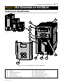
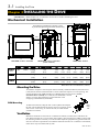

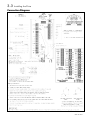
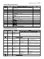
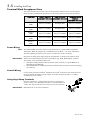
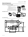
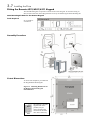
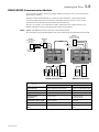


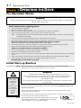
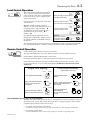
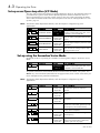

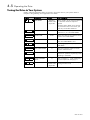


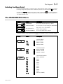
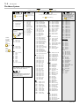

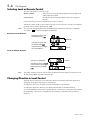
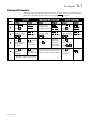
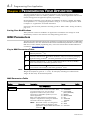
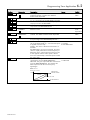


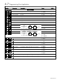
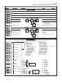
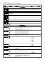

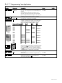


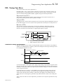
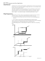
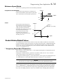

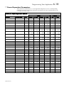

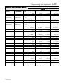

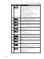
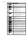
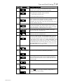
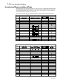


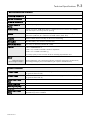


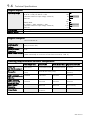
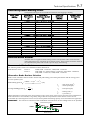


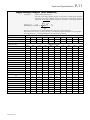
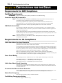
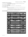
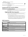
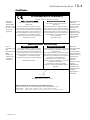

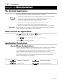


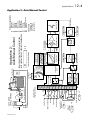
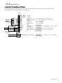

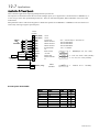


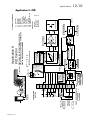
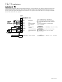
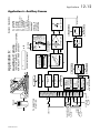


![[AC10] : HA502320U001 : Product Manual to support the Parker](http://vs1.manualzilla.com/store/data/006162733_1-f6c7f4023b54f3efd3a5308c67bef951-150x150.png)