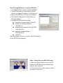
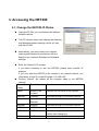
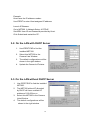
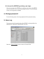
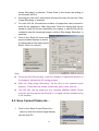
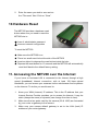
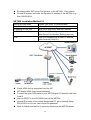
1
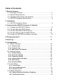
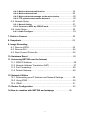
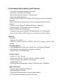
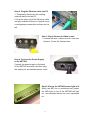
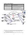
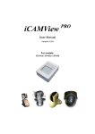
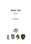
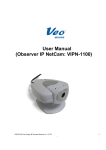
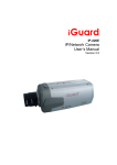
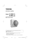
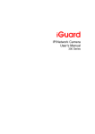
www.sightwatch.com
Model: NET200
NETWORK VIDEO SERVER
OPERATING INSTRUCTIONS
Table of Contents
1.System Features
1-1. Package Contents … … … … … … … … … … … … … … … … … … ..… .3
1-2. System Requirements… … … … … … … … … … … … … … … … … .… .3
1-3. Hardware Description and Features… … … … … … … … … … … ..… 4
1-4. NET200 Hardware Specification… … … … … … … … … … … … … … .5
2. Installation
2-1. NET200 Hardware Setup… … … … … … … … … … … … … … … … .… 5
3. Accessing the NET200 (Connect to Camera)
3-1. Change the NET200 IP Status… … … … … … … … … … … … … … … 9
3-2. On the LAN with DHCP Server… … … … … … … … … … … … … … 10
3-3. On the LAN without DHCP Server… … … … … … … … … … … … ..10
3-4. On the LAN use with the ADSL Router… … … … … … … … … … ..11
3-5.Access the NET200 by ordinary user login… … … … … … … … … ..12
4.Change password… … … … … … … … … … … … … … … … … … … … … .12
5.View Log… … … … … … … … … … … … … … … … … … … … … … … … … ..12
6. Configuration
6-1. System Settings… … … … … … … … … … … … … … … … … … .… … .14
6-1-1. Camera name… … … … … … … … … … … … … … … … … … … … ...14
6-1-2. Camera’
s time… … … … … … … … … … … … … … … … … … … … ..14
6-1-3. Web Server Port Number… … … … … … … … … … … … … … … … .14
6-2. Camera Control… … … … … … … … … … … … … … … … … … … … ..15
6-2-1. Quality Setting… … … … … … … … … … … … … … … … … … … … .15
6-2-2. Resolution Setting… … … … … … … … … … … … … … … … … … ...15
6-2-3. Frequency Setting… … … … … … … … … … … … … … … … … … … 16
6-2-4. Camera Advanced adjust… … … … … … … … … … … … … … … … .16
6-2-5. Split setting… … … … … … … … … … … … … … … … … … … … … ..16
6-2-6. Operation Mode… … … … … … … … … … … … … … … … … … … … 17
6-3. User Setup… … … … … … … … … … … … … … … … … … … … … … ..17
6-3-1. Current User… … … … … … … … … … … … … … … … … … … … ...17
6-3-2. Account Management… … … … … … … … … … … … … … … … … .17
6-3-3. Delete Account… … … … … … … … … … … … … … … … … … … … 18
6-4. Motion Detection… … … … … … … … … … … … … … … … … … … … .19
6-4-1. Motion Detection Enabling / Disabling… … … … … … … … … … ..19
6-4-2. Set Detection Area… … … … … … … … … … … … … … … … … … .19
1
6-4-3. Motion detected mail function… … … … … … … … … … … … … .19
6-4-4. Motion detected mail… … … … … … … … … … … … … … … … … 20
6-4-5. Motion detected message on the main window. … … … … … … .20
6-4-6. FTP uploads when motion detected. … … … … … … … … … … ...20
6-5. Network Setup… … … … … … … … … … … … … … … … … … … … … 21
6-5-1. Manual Setting … … … … … … … … … … … … … … … … … … ...21
6-5-2. Connect to ADSL by PPPOE mode… … … … … … … … … … … … 21
6-6. Audio Setup… … … … … … … … … … … … … … … … … … … … … … 23
6-6-1. Audio Configure… … … … … … … … … … … … … … … … … … … .23
7. Delete a Camera… … … … … … … … … … … … … … … … … … … … … … 23
8. Snapshots… … … … … … … … … … … … … … … … … … … … ..… … … … 23
9. Image Recording
9-1. Save as JPEG… … … … … … … … … … … … … … … … … … … … … 23
9-2. Save as AVI… … … … … … … … … … … … … … … … … … … … … … .24
9-3. Save Current Picture As… … … … … … … … … … … … … … … … … 25
10. Hardware Reset… … … … … … … … … … … … … … … … … … … … … ...26
11. Accessing NET200 over the Internet
11-1. WAN IP Address… … … … … … … … … … … … … … … … … … … … 26
11-2. Network Address Translation (NAT) … … … … … … … … … … … ..27
11-3. Port Forwarding… … … … … … … … … … … … … … … … … … ..… ..28
11-4. Default Gateway… … … … … … … … … … … … … … … … … ..… .… 28
12. Network Utilities
12-1. Determining your IP Address and Network Settings… … … … ..29
12-2. Using PING… … … … … … … … … … … … … … … … … … … … … ...30
12-3. IPEdit… … … … … … … … … … … … … … … … … … ...… … … … … ..31
13. Router Configuration… … … … … … … … … … … … … … … … … … … .32
14.How to combine with NET200 and webpage … … … … … … .38
2
Introduction
The NET200 is an Internet-based digital media server, video source and audio
source to distribute their compressed live video and audio into Intranet-Internet
through an Ethernet connection. It is a self-contained Web Server, so users
could access the NET200 just browsing a website over the Internet using a
standard browser such as Explorer or another browser, and do all the
management, configuration, and monitoring easily. NET200 contains image
compression chipset that is capable of delivering standard JPEG, MJPEG, and
real-time video into a limited network bandwidth.
1. System Features
1-1. Package Contents
1.
2.
3.
4.
5.
6.
7.
8.
9.
NET200
Power Adapter
Red Color 10/100 Mbps Ethernet LAN Cable
(MDI / X, Cross over LAN cable)
Blue Color 10/100 Mbps Ethernet LAN Cable (MDI)
NET200 installation CD-ROM
User Manual
Climbers with screws
Warranty card
Rubbers x 4
1-2. System Requirements
To view the camera web page
w Web Browser – Internet Explorer for Windows 5.0 or higher
w PC with Windows 98/98SE, ME, 2000, or XP connected to LAN
To run the included software (IPEDIT) applications
w PC - Intel Pentium III or equivalent, 500MHz or above, 64MB RAM, 150 MB
Hard Disk Space, 800x600 resolution with 16- bit color
w Windows 98/98SE, ME, 2000, or XP
To access cameras from the Internet
w Broadband Internet Connection (DSL, Cable Modem) with min. 128k upload
speed
3
1-3. Hardware Description and Features
w Connect to any analog camera (Color, B/W)
w Connect TV and DVD / VCD Player
w Built-in Microphone with Audio / Video Function
w Real-Time Motion Detection
w Support TCP/IP, SMTP, FTP, PPPoE, DCHP (Dynamic Host Configuration
Protocol)
w Built-in web server allows camera to be accessed by standard Internet
browser
w Network RJ45: 10Base-T/100Base-TX Ethernet networks
w Network ready, IP addressable (no PC is required.)
w Motion-JPEG based compression
w 5 different resolutions: 640x480, 352x288,320x240,176x144,160x120
w Record AVI or Motion JPEG images on to hard disk for future viewing
Network
w Fixed IP.
w Dynamic IP by DHCP.
w Directly connect to ADSL by PPPoE, mail the IP setting to preset mail
address.
User Management
w User Management for Add User, Delete User, and Change Password.
w Administrator, privileged user to change any settings.
w General users, view images only.
Camera Control
w Layout: 1x1, 2x2, 3x3, 4x4.
w Resolution: 160x120, 176x144, 320x240, 352x288, 640x480.
w Quality: Highest, High, Medium, Low, Lowest
w Image Rotate / Flip.
w Video Adjustment: Brightness, Contrast, Saturation, Hue, Sharpness
Motion Detection
w Software Real-Time Motion Detection.
w Selected Region Provided.
w E-Mail the Detected Images to preset e-Mail address.
w FTP the Detected Images to preset FTP server.
4
Browser Support
w IE only (ActiveX Control) save the current image local PC.
w ActiveX controls: ActiveX controls support full functions, including the Right
Mouse Button Menu control.
Utility
w IPEDIT.EXE to scan the Installed IP-Cams and change the Camera Name
and IP Address
1-4. NET200 Hardware Specification
w Built-in web server allows camera to be accessed by standard Internet
browser
w Network, RJ-45: 10Base-T/100Base-TX Ethernet networks
w Network ready, IP addressable (no PC required.)
w Motion-JPEG based compression
w Size: 91 mm x 65 mm x 53 mm
w Weight: 163 g
w Power Supply: 5.1 VDC/2A
2. Installation
Before installing the IP- Box, You should have an available Ethernet LAN
connection (RJ-45 port). To view the camera’
s image or make any manual
configuration changes, you will need a Windows PC with Internet Explorer 5.0
or higher and connection to the LAN.
2-1. NET200 Hardware Setup
1.
2.
3.
4.
5.
6.
Insert the power-cord to NET200.
Insert the Network Line to NET200 and Computer LAN Card RJ-45 port
(Red color LAN Cable).
Equip Camera to Video-in port, Power-On the Camera
Power-On the Computer for IP setup.
Use the IPEdit.exe tools to find the NET200.
Use IE to view the NET200 image.
Step1.Plug the Ethernet cable onto NET200
Plug the included RED Color Ethernet cable into the
RJ-45 connector at the back of the NET200 as
shown.
5
Step 2. Plug the Ethernet cable into PC
1. Temporarily disconnect the existing
network cable from the PC.
2. Plug the other end of the Ethernet cable
into any available LAN port. A typical home
router/gateway connection is shown on the
left.
Step 3. Equip Camera to Video-in port
1. Connect the BNC Cable to the NET200 from
Camera , Power-On Camera then
Step 4. Connect the Power Supply
to the NET200
Connect the power supply to the back
of the NET200 as shown, and then plug
the supply into an available power outlet.
Step 5. Ensure the NET200 power light is lit
When the NET200 is connected with power,
the LED light on top of the NET200 will light
up. This indicates that the NET200 is powered
on.
6
Step 6. Using IPEdit.exe to test the NET200
1. Use IPEDIT.EXE to find the installed NET200
2. The NET200 without IP allocated by DHCP
will have a default IP address of 169.254.xx.xx
3. Select this NET200 on Camera List Window.
4. The default configuration will be shown on
the right window.
5. Change NET200 network settings.
u Update the Camera Name (Fixed IP).
u Update the Gateway Address
(192.168.0.1).
u Update the IP address of this NET200
. (192.168.0.30).
u Update the Network Mask
(255.255.255.0).
u ‘
Submit’it.
After the “Submit ”button is clicked, The IP information
of this NET200 will updated.
Step 7. Using IE to view NET200 image
1. Start the Internet Explorer, key in the IP
Address of NET200 into the Address field,
such as 192.168.0.245.
2. Turn the lens to the left or right to adjust
the clarity of the focus.
7
Step 8. Connect NET200 to the ADSL Modem or
LAN Hub
1. Remove the red network cable from the
PC when all the settings are completed.
2. Reconnect the existing network cable to
the PC.
3. Using the blue network cable provided,
connect one end to the NET200, and the
other, to the ADSL model of LAN hub.
Step 9. View NET200 Image
Remotely
When all settings are completed, you
will be able to enter the NET200’
s IP
address through the remote PC’
s IE
and view the real-time NET200 image.
8
3. Accessing the NET200
3-1. Change the NET200 IP Status
u
Using the IP-Edit, you could select the different
Network options.
u
The PC network options will display the Gateway
and Netmask network settings, which you can
edit with IP-Edit.
u
Alternatively, you may contact your network
system administrator to provide you with the
details of your network Gateway and Netmask
settings.
u
Enter the Camera’
s IP number.
If you allow outsiders to see the NET200, please enter another IP
address.
If you only want the NET200 to be viewed in the internal network, you
could enter a local IP number Example: 192.168.0.99.
Clicking “Submit” will update all the changes made to the NET200
settings.
u
Option
Labels
Translations
Functions
Name:
Name of the
Camera
Options for the name of the camera
Gateway
Gateway
Reviews through your network options
IP
Network
Address
Netmask
Network
Reviews through your network options
HTTP Port 1
HTTP Port 1
80
HTTP Port 2
HTTP Port 2
IP address given by the administrator,
refrain from changing it
MAC
MAC Address
9
Example:
Hinet uses the IP address number:
Use IPEDIT to enter Hinet assigned IP address.
Launch IE Browser.
Go to NET200 à Network Setup à PPPoE.
Set ADSL User ID and Password provided by Hinet.
Click Submit and restart the PC.
3-2. On the LAN with DHCP Server
1.
2.
3.
4.
Use IPEDIT.EXE to find the
installed NET200.
Select this NET200 in the
Camera Lists Window.
The default configurations will be
shown in the right window.
Update the Camera’
s IP status.
3-3. On the LAN without DHCP Server
1.
2.
3.
4.
Use IPEDIT.EXE to find the installed
NET200.
The NET200 without IP allocated
by DHCP will have a default IP
address of 169.254.xx.xx.
Select this NET200 in the Camera
Lists Window.
The default configurations will be
shown In the right window.
10
1. Update the Camera Name (Fixed IP)
2. Update the Gateway Address (192.168.0.1).
3. Update the IP address of this NET200 (192.168.0.30).
4. Update the Network Mask (255.255.255.0).
5. ‘
Submit’it.
After the button ‘
Submit’is clicked, the IP information of this NET200 will be
updated.
Access this NET200 by this IP address; on the Configuration -> Network, the
Fixed IP address was assigned.
3-4. On the LAN use with the ADSL Router
If the NET200 was installed on the ADSL router, the NET200 will dynamically
be allocated an IP address from the DHCP server. However, if the NET200
wants to be accessed from the WAN, the NET200 IP address needs to be
setup as fixed IP. It is the same for the Virtual Server function of ADSL router,
which needs to be setup as well.
1.
Setup the NET200 as Fixed IP, such as 192.168.0.49.
2. Enter the administrator page of +ADSL router. (Use sonnet ASDL router as
an example).
3.
Enter the Virtual Server Page.
A. Setup the mapping of HTTP Port (80) to 192.168.0.49.
B. Restart the ADSL router.
Then the NET200 can be accessed from WAN, by the ADSL WAN IP Address.
11
3-5. Access the NET200 by ordinary user login.
If the user accesses the NET200 by an ordinary user account, the NET200
would not allow the user to access the privileged functions. From the following
screen, the Configuration is disabled.
4. Change password
From the following screen, the change password will be passwords setting
5. View Log
The user can check the log information of the NET200, including the Main Info,
Appended Info, Operator IP, Operator MAC, and Time.
Select the ”Camera Window”button to return to Camera mode.
12
6. Configuration
Only the administrator can select the “Configuration”, the ordinary user
account does not have this privilege to access this function.
The screen is the main menu for configuration setting,
When the administrator selects the “Configuration”in
the main window.
NET200 provides 7 types of configurations:
n
System Settings
n
Camera Control
- Quality, Resolution, Splits settings
n
User
- To add / delete user, change password;
enable/disable user check.
- Add User.
- Change Password.
- Delete User Account.
n
Motion Detection
- Enable/Disable motion detection.
- Motion detected mail setting.
- Motion detected FTP setting.
n
Network – NET200 Network connection setting.
- DHCP – setting the IP dynamically.
- Fixed IP – setting the IP manually.
- Connect to ADSL by PPPoE.
n
AUDIO – Audio Configure
n
DDNS - DynDNS
13
6-1.System Setting
6-1-1. Camera Name
The camera name can be set on the “Camera Name”field, and select
“change “to summit it.
6-1-2. Camera’
s time
Select “NTP”button
Key in the Sever IP address Like: http://www.org.ntp.org
Presses “adjust”to activate.
After NET200 get the time from NTP sever, it will update the Camera’
s time
field.
Select “Input new time”button and click on “Synchronize with PC's time “
Key in “mm/dd/yyyy”format into “Date “field, and “hh:mm:ss”by 24hours
format into “Time “
Filed, then select the “Adjust”button to adjust the time!
6-1-3. Web Server Port Number
The implementation supports 2 HTTP port settings. The HTTP “Port 1”is set to
80, the HTTP “Port 2”is set to 8080. The user can access the NET200 by
http://xx.xx.xx.xx/
or
http://xx.xx.xx.xx:8080/
to access the NET200
It is recommended to keep the HTTP “Port 1”as 80 to make sure the NET200
can be accessed by the default HTTP port setting access on the LAN.
http://xx.xx.xx.xx/
If multiple NET200s are installed on the LAN, also required to be accessed
from the WAN, the HTTP “Port 2”can be changed as the virtual server port
14
mapping to support multiple NET200s. The following table lists example
configurations.
NET200 IP
HTTP
HTTP
Virtual
port.1
port.2
Server Port
Access NET200 on LAN
Setting
192.168.1.1
80
8080
8080
Access NET200 on WAN
IP: 68.68.68.68
è
http://192.168.1.1
http://68.68.68.68:8080
192.168.1.1
http://192.168.1.1:8080
192.168.1.2
80
8081
8080
è
http://192.168.1.2
http://68.68.68.68:8081
192.168.1.1
http://192.168.1.1:8081
192.168.1.3
80
8082
8080
è
http://192.168.1.3
http://68.68.68.68:8082
192.168.1.1
http://192.168.1.1:8082
6-2.Camera Control
On the IE Browser, right mouse click on the video to activate a pop-up menu.
You can then change the camera settings accordingly.
6-2-1. Quality Setting
The NET200 provides 5 image quality settings. The user can select the Quality
setting from the Quality list box.
l
l
l
l
l
Low
High
Medium
Low
Lowest
Note: The value in the list box displays the current setting of the current image.
When you make a new selection, the value on the list box will be changed to
the new image quality settings.
15
6-2-2. Resolution Setting
NET200 provides 5 resolutions,
l 640 X 480
l 320 X 240
l 352 X 288
l 176 X 144
l 160 X 120
User can select the desired new setting from the “Resolution”list box.
Note: The value in the list box displays the current setting of the current image.
When you make a new selection, the value on the list box will be changed to
the new image quality settings.
6-2-3. Frequency Setting
NET200 provide the Frequency setting for
l
l
l
Outdoor
Indoor & 50
Indoor & 60
6-2-4. Camera Advanced Adjust
NET200 provide the advanced setting for
l
l
l
l
l
Brightness
Contrast
Saturation
Hue
Sharpness
To control the camera, use the “+”to increase, “-“to decrease it, or
“STD”to return to default value.
6-2-5. Split Setting
The NET200 provides 4 settings for split windows. It can display different time
frame images of the selected NET200. The time string with green characters is
16
the current displayed image.
4 types of Split window,
l
l
l
l
1 x 1 (Default)
2x2
3x3
4x4
Note: The images on the split window are on the same camera, but with
different time. It is useful on the low frame rate condition, and then user
can check the images that are the recently got.
6-2-6. Operation Mode
Continuous Mode: The NET200 will always try to capture the image as fast
as possible. This is the default setting.
Periodic Mode: ms (mill-second) or
s (second) can be set. The value set
here must be greater than 0.
Setting the periodic mode to 5 seconds will update the image every 5 seconds.
The time interval can be checked by the time displayed on the image.
6-3. User Management
6-3-1. Current User
If you are logging in for the first-time, the
user name in the “Current User”section
should display “administrator”.
17
6-3-2. Account Management
User authorization required:
Checking the “Enable use check”check box will
enable the user check when the users want to access
the NET200. The Login window will prompt for
the User name and Password.
If the check box is not checked, then the user check
will not be enabled. All users can access the
NET200 directly, with the administrator’
s permission. A Login window is not
required.
Note: Before you select “Enable user check”check button, please remember
to change the administrator password.
Add a user or change password:
Enter a new user name and password information to create a new user
account, or enter an existing user account, then set a new password to replace
the old password.
Confirm by clicking on the [Change/Create] button to create the account or
change password.
After submitting, the “Current User List:”would display the newly created user
account. In this example: “newuser”.
6-3-3. Delete Account
Select the user account from the “Username”list box.
Click the [Delete] button to delete the selected user account. A confirmation
window will prompt the user to select “OK”or “Cancel”.
After selecting the “OK”button, the selected user account will be deleted from
the “Current User List”. In this example, the “newuser” account will be
removed.
18
6-4. Motion Detection
6-4-1. Motion Detection Enabling / Disabling
Check the “Enable motion detection”check
box to activate the motion detection.
If the check box is not checked, the motion
detection send mail function will not be
enabled.
Enter the “Sensitivity “button for select “High”or “Middle “and “Low “mode.
6-4-2. Set detection Area
When motion detection enabling,
the user can selected the red line
area for security, the mail function
will send the motion-detected images
to the preset mail address
6-4-3. Motion detected mail function (mail setting)
When motion detection is enabled, the user can setup the mail function to send
the motion-detected images to the preset mail address. The procedures are as
follow:
1. Motion Detect set to “Enable”state.
2. Setup the “SMTP Mail Server”and e-Mail address. (password use or not)
3. Enter the sender’
s email address in “Sender”field and the recipient’
s email
address in the “Receiver”field.
4. The user can change the “Subject”field.
5. If the mail server needs authentication, check the “Password”check box.
19
Also, enter the password; otherwise the “Password”field does not need to
be filled in.
6. Check the “Send mail when motion detected” check box to enable the
operation. If the check box is not checked, the motion detected send mail
function will not be enabled.
7. Confirm by selecting [Send Setting] option to save the settings.
Note:
If all of the items are enabled resulting in a motion event detection, the
NET200 will send the motion-detected images to the preset email address.
The maximum number of images allowed is 6 images per mail.
6-4-4. Motion detected mail
The received mail will be displayed
in a motion picture form. It can also
be displayed as separated images
with a selection of the circle button
on the left side of the Image Viewer.
6-4-5. Motion detected message on the main window.
When the motion detection function is enabled, and a motion detected, a
message will be displayed at the bottom.
Motion detection disabled or Motion detection enabled
6-4-6. FTP uploads when motion detected.
The motion-detected images can also be uploaded to FTP server. The
procedures are as follow:
1. Enter the IP address or domain name of the “FTP Server”.
2. Enter the “Username”and “Password”of the FTP server.
3. Certain FTP servers need an “Account” field. Leave it blank if it is not
needed.
20
4. Enter the “Remote folder”upload path information for saving the images.
5. Confirm by selecting the [Send Setting] option to save the settings.
6-5. Network Setup
6-5-1. Manual Setting
For fixed IP address users:
On the network environment, the
administrator can assign a unique
IP address to each NET200.
The procedures are as follow:
1. Check the “Manually”radio button.
2. Enter the “IP Address”, “Network Mask (Subnet mask)”, “Default gateway”,
and the “DNS1”, “DNS2”, as well as ‘
DNS3”in formations.
3. Select “Reboot immediately”to reboot the NET200 to allow these settings
to take effect.
DHCP
The “DHCP”is automatically set as the default network setting of NET200.
When an NET200 is joined into the LAN, it will issue the DHCP packets to
request an IP address that is dynamically assigned by the DHCP server. If it is
unable to get a DHCP address on a limited tries, the NET200 will assign a
default IP address such as “169.254.xx.xx”.
6-5-2. Connect to ADSL by PPPoE mode.
The NET200 can directly connect to the ADSL. However, it should be setup on
the LAN environment to setup the PPPoE information before connecting to the
21
ADSL modem. Power on the NET200 and it will dial in to the ISP connection to
the WAN via the ADSL modem.
The procedures are as follow:
1. Connect to the LAN by DHCP or Fixed IP
Access the NET200 and enter [Configuration] è [Network Setup]
PPPoE Configuration
select the “Dial on power Up”check box.
If the ADSL Modem and NET200 are connected on a hub and after the
PPPoE in formations are entered, you can then select the “Save and Dial
Now”option to do the PPPoE dial.
6. Enter the “User” and “Password” fields with the account and password
provided by the ISP. If the “Mail after dialed”check box is checked, the mail
will be automatically sent when connected automatically to the ISP.
7. If the mail server needs authentication, the “Password”check box needs to
be checked and password information, entered.
8. Enter the sender’
s email address in the “Sender email”field and recipient’
s
email address in the “Receiver email”field.
9. The “Subject”field can be modified.
10. Confirm by clicking on the “Save”button
to save the settings.
2.
3.
4.
5.
If the NET200 and ADSL modem are connected
by a hub, the administrator can select ”Dial Now”
to perform the connect operation. On the contrary,
if the NET200 and ADSL modem are connected
directly, then there is a need:
n
n
n
n
n
n
To power off the NET200,
To connect to the ADSL modem,
To power-up the NET200,
For the NET200 to start dialing.
Once connected, mail the IP address information to the preset e-mail
address.
After 10 times of failed try connections, it aborts the dialing operation and
the administrator can reconnect it to the LAN, access it, to find the cause.
22
Note:
If the PPPoE option “Mail after dialed”is selected, and when PPPoE dials in to
the ISP, a mail that contains the Dial Up ISP Address / Netmask / Gateway
address / DNS Server address will be mailed to preset the e-Mail address.
6-6.AUDIO Setup
6-6-1 Audio Configure
For fixed Audio option users:
check the “Audio format ”check
box to select “PCM”or “Adpcm”
If the check box is not checked, default setting will be “PCM”!
Check the “Audio On/Off “ button for select “On” or “Off “mode for audio
enabled.
7.Delete a Camera
NET200 can support view of multiple IP-Cams or NET200, you can add
a new one into this WebPage by input such as http://192.168.0.50/ on
the Watching field. Also a viewed new camera can be removed by
select this NET200, then press “Delete a camera”to remove it from the
WebPage.
8.Snapshots
The user can capture single pictures by this button.
9.Image Recording
9-1. Save as JPEG
1.
2.
Select “Image Recording… ”
The “Image Recording” pop-up window displays. Check the “Save as
23
JPEG”check box option.
3.
Enter the “Download Number”to save the desired number of images, or
“Download No Limit” to save the images continuously, until the “Stop
Image Recording”is selected.
4.
Click on the “Save As”button and
a pop-up window displays to select
the save path and file name prefix.
Select “Save”to continue.
5.
Click on the “Start”button to perform
the image download process and save
the JPEG files into the local PC.
Note:
n
During the downloading and saving process, a yellow mark will be
displayed on the right-down position to indicate the saving process.
n
Before the “Download Number”of images is reached, or if you may have
selected “Download No Limit”, click on “Stop Image Recording”to stop the
image recording process.
After the “Stop Image Recording”, list the files on the selected saved directory.
These files are named
As file_name_prefixed_yyyy_mm_dd_hh_mm_ss_ms.jpg
9-2. Save as AVI
1.
2.
Select “Image Recording… ”
The “Image Recording” pop-up window displays. Check the “Save as
3.
JPEG”check box option.
Enter the “Time”, “Number” or “Size” on each AVI file, until the “Stop
24
4.
5.
6.
Image Recording”is selected. “Frame Rate”is the frame rate setting of
the recorded AVI file.
Selecting the “No Limit”radio button will save the video file until the “Stop
Image Recording”is selected.
For each AVI file, the maximum number of images that can be saved in
each file are specified in “Max Jpeg Num”Once the images that can be
saved on each AVI file are reached by this number, a new AVI file will be
created to save the remaining images, until the “Stop Image Recording”is
selected.
Click on the “Save As”button and a
pop-up window displays to select
the save path and file name prefix.
Select “Save”to continue.
Note:
n
During the AVI file recording, a red icon displays on right-down position of
the image to indicate the AVI saving process.
n
After the “Stop Image Recording”, list the files on the selected saved
directory. These files are named as filename_prefix_date_time.avi.
n
The AVI files can be played by any standard Windows Media Player
program, but they require the DixectX 8.1 or higher version software driver
to be installed.
9-3. Save Current Picture As…
1.
Click on the “Save Current Picture As …
”option to save the current image display
into the local PC.
25
2.
Enter the name you wish to save as into
the “File name”field. Click on “Save”.
10.Hardware Reset
The NET200 provides a hardware reset
button when ever you need to reset the
NET200 due to
Loss of administrator password
Incorrect network configuration
Reset
To reset the NET200
Make sure the NET200 is on.
There is a small reset hole at the side of the NET200
Insert an object to depress the reset button inside the hole
Depress the reset button for 10 seconds and the NET200 will automatically
reset itself back to the default factory setting.
11. Accessing the NET200 over the Internet
If your home or business LAN is connected to the Internet through a high
speed (broadband) Internet connection, with at least 128 kbps upload
bandwidth, you can access your cameras via the web browser from anywhere
on the Internet. To do this you would need to:
1.
2.
3.
Know your WAN (Internet) IP address. This is the IP address that your
Internet Service Provider provides you to access the Internet. It may be
static (always the same) or dynamic (can change from time to time).
Make sure the two ports used by the camera (80 & 1600) are forwarded
by your router or gateway to the camera.
Make sure your camera default gateway is set to the LAN (local) IP
address of your router/gateway.
26
11-1. WAN IP Address
The WAN (Wide Area Network) IP address that your Internet Service Provider
provides you so that you can access the Internet is very different from the LAN
or local IP address that your PCs and cameras are using to connect to your
local network. Your WAN or Internet IP address is visible to the outside world
(Internet) whereas your local addresses are not. To find your home or business
network from the Internet you must know your WAN IP address.
Your WAN IP address is stored by your gateway router, which uses it to
connect to the Internet. All the devices on your network connect to the Internet
via your gateway router. You can find your current WAN IP address by
checking your router status page. There are also various websites such as
www.whatismyip.com which, will tell you the IP address that you are currently
using to access the Internet.
A word about terminology
The term gateway is used generically to define a device that connects a local
network to the Internet. A gateway may be a router, a PC running software,
which allows it to act as a gateway such as a proxy server, or some other
device. Most home networks use a NAT (Network Address Translation) router
as a gateway. The term gateway router refers to such a device.
Static versus Dynamic IP address
The IP address (or addresses) your ISP has (have) provided you will either be
static, which means it never changes, or dynamic, meaning it can change
periodically. Dynamic addresses present an additional challenge when trying
to locate your network from the Internet since your address may have changed
since the last time you checked it. How often your dynamic address changes
varies from one service provider to another. Also, any time you reboot your
cable or DSL modem, you are likely to get a new address when reconnecting.
The solution to the ever-changing IP address is known as DDNS or dynamic
domain name service. A DDNS will allow you to find your network by a domain
name, such as mynetcam.no-ip.com, rather than needing to know the IP
address.
27
11-2. Network Address Translation (NAT)
Most home routers and business firewalls today perform something called NAT
or Network Address Translation. NAT translates your external or WAN IP
address into an internal address inside your gateway router. What this means
is, you can think of your router as being divided into two halves, the LAN side
(inside) and the WAN side (outside or Internet side). When a connection
request arrives at your router from the Internet, it will not get any farther than
the WAN side unless you have specifically instructed your router to pass this
type of request to a specific device on your LAN. This process is know as port
forwarding or port redirecting.
11-3. Port Forwarding
All TCP/IP (Internet) networking uses software ports. Ports can be thought of
as channels on your television. By default, all web page traffic is on channel
(port) 80. By default, the NET200 uses port 80 to deliver its web page to your
browser and port 1600 to send video. Therefore, both of these channels (ports)
must be open (not blocked by your router/firewall) to incoming traffic in order
for you to connect to the camera from the Internet.
Also, these two ports must be forwarded or redirected to the camera’
s LAN IP
address by your gateway router. Your router’
s setup software should provide a
utility for port forwarding or redirecting. Router configuration contains setup
help for some popular home networking gateway routers currently on the
market.
Note: Forwarding ports to your camera does not pose any additional security risk to your LAN.
Before setting up port forwarding, it is best to configure your camera to use a static LAN IP
since your port forwarding setup will need to be updated if the camera’
s LAN IP address
changes.
11-4. Default Gateway
Devices (PCs, cameras, etc.) on your network connect to the Internet via a
gateway. For most home networks, a NAT type router serves as the gateway.
For business LANs, the gateway may be a PC running gateway software. In
order for any device on your network to get connected to the Internet, it must
know the LAN IP address of your gateway. If your camera is set up to use
DHCP, then it will retrieve this information automatically from your router.
28
However, if you have configured your camera to use a static IP address, you
must also be sure that you have set the correct gateway IP address in order to
connect your camera to the Internet. You camera is now live on the Internet.
Browsing your camera from the Internet is the same as browsing on your LAN
except that you must enter your WAN IP address instead of the LAN IP
address.
12. Network Utilities
Microsoft Windows includes various network information utilities to determine
various network configurations. To determine your IP address and network
settings, follow the steps below, depending on your operating system.
12-1. Determining your IP Address and Network Settings
Windows 98/Me:
1. Click on Start è Run and type in: command and then press ENTER
2. In the MS- DOS window, type in: winipcfg and then press ENTER
3. This will display your network card’
s Adapter Address, IP Address, Subnet
Mask, and Default Gateway.
More information regarding WINIPCFG can be obtained by typing in: winipcfg /?
at the MS -DOS prompt.
WINIPCFG is located in the C: \Windows folder.
Windows 2000/XP:
1. Click on Start è Run and type in: command and then press ENTER
2. In the MS- DOS window, type in: ipconfig and then press ENTER
3. This will display your network card’
s IP Address, Subnet Mask, and Default
Gateway.
More information regarding IPCONFIG can be obtained by typing in: ipconfig /?
at the MS - DOS prompt.
IPCONFIG is located in the C: \Windows \System32 folder.
29
12-2. Using PING
PING is a very useful utility for checking to see if a camera is responding or
checking to see if an IP address is available. In Windows 98/Me, PING is
located in C: \Windows. In Windows 2000/XP, PING is located in C: \Windows
\System32.
Windows 98/Me/2000/XP:
1. Click on Start ->Run and type in: command and then press ENTER
2. In the MS- DOS window, type in: ping XXX.XXX.XXX.XXX and then press
ENTER (where XXX.XXX.XXX.XXX is your IP address) For example, if
your Camera uses the IP address of 123.123.123.1, you would type in:
ping 123.123.123.1
3. If there is a camera, or a PC or other network device online and using this
address you will see:
Pinging 123.123.123.1 with 32 bytes of data:
Reply from 123.123.123.1: bytes=32 time<1ms TTL=128
Reply from 123.123.123.1: bytes=32 time<1ms TTL=128
Reply from 123.123.123.1: bytes=32 time<1ms TTL=128
Reply from 123.123.123.1: bytes=32 time<1ms TTL=128
Ping statistics for 123.123.123.1:
Packets: Sent = 4, Received = 4, Lost = 0 (0% loss),
Approximate round trip times in milli-seconds:
Minimum = 0ms, Maximum = 0ms, Average = 0ms
If there is NO response on this address you’ll see
Pinging 123.123.123.1 with 32 bytes of data:
Request timed out.
Request timed out.
Request timed out.
Request timed out.
Ping statistics for 123.123.123.1:
Packets: Sent = 4, Received = 0, Lost = 4 (100% loss),
This indicates that the address is available for use. However, there could still
be a device that is currently offline, which is configured to use the address. To
30
be certain, make sure all your network devices are on and connected to your
network when checking for address availability.
12-3. IPEdit
IPEDIT.EXE is used to scan the Installed NET200s and set the Camera Name
and IP Address.
13. Router Configuration
The following section describes the initial configuration of the router and port
forwarding for some of the most common routers from 3Com, Belkin, D-Link,
Linksys, Microsoft, NETGEAR, Proxim, Siemens, and SMC.
In order to access the OTC IP-Camera/Wireless IP-Camera from the Internet,
you’
ll need to configure your router to use ports 80 and 1600 (default settings).
Port 80 is used for accessing the camera’
s homepage and Port 1600 is used
for authentication and video streaming. If your Internet Service Provider blocks
ports 80/1600, you’
ll need to reconfigure your camera and router to other ports
such as 81/1601, 82/1602, etc. To change the port settings on the camera,
you’
ll need to use the IP-Cam Setup Utility [Refer to Chapter 5: IP-Cam Setup
Utility].
Follow the steps below to configure your router, depending on the router
manufacturer and model. If your particular router manufacturer or model is not
listed below, please contact your router manufacturer for further assistance in
configuring the router.
3Com (http://www.3com.com)
OfficeConnect Cable/DSL Gateway - [3C857-US]
OfficeConnect Wireless Cable/DSL Gateway - [3CRWE52196]
1. Log into your router.
2. On the main page, select Firewalls on the left side of the page.
3. Select the Virtual Servers tab at the top of the page.
4. Click New on the right side of the page to open the Virtual Server Settings
dialog box.
5. Type in the camera’
s IP Address in the Server IP Address text box. (Look
on the NET200 ‘
s IP Address LCD Display for the last 3 digits of the
31
6.
7.
8.
9.
camera’
s IP Address.)
Under Local Service, select Custom.
Under Custom Service Name, type in: NET200.
Under Specify Custom Service Ports, type in: 80, 1600.
Click Add to save the settings. The NET200 should now be configured to
work with your router and be accessible from the Internet.
Belkin (http://www.belkin.com)
Wireless Cable/DSL Gateway Router - [F5D6230-3]
1.
2.
3.
Log into your router.
On the main page, select Virtual Server on the left side of the page under
the Security section.
Enter the following information on the page:
Line #1:
Private IP:
Private Port:
Type:
Public Port:
Type in the camera's IP address.
80
TCP
80
Private IP:
Private Port:
Type:
Public Port:
Type in the camera's IP address.
1600
TCP
1600
Line #2:
4.
Click Enter to save the settings. The NET200 should now be configured to
work with your router and be accessible from the Internet.
54g Wireless DSL/Cable Gateway Router - [F5D7230 -4]
1.
2.
3.
4.
Log into your router.
On the main page, select Firewall on the left side of the page.
Under Firewall, select Virtual Servers.
Enter the following information on the page:
32
Line #1:
Private IP:
Private Port:
Type:
Public Port:
Type in the camera's IP address.
80
TCP
80
Private IP:
Private Port:
Type:
Public Port:
Type in the camera's IP address.
1600
TCP
1600
Line #2:
5.
Click Apply changes to save the settings. The NET200 should now be
configured to work with your router and be accessible from the Internet.
D-Link (http://www.dlink.com )
DI -604/DI-614+/DI-624
1. Log into your router.
2. On the main page, click on Advanced at the top of the page.
3. On the left side of the page, click on Virtual Server. Note: Make sure DMZ
host is disabled. If DMZ is enabled, it will disable all Virtual Server
entries.
4. Enter the following information on the page:
Enabled/Disabled: Enabled
Name:
OTCWeb
Private IP:
Type in the camera's IP address, for example: 192.168.0.3
Protocol Type:
TCP
Private Port:
80
Public Port:
80
Schedule:
Always
5.
6.
Click Apply to save the settings.
Enter the following information on the page:
Enabled/Disabled: Enabled
Name:
NET200
33
Private IP:
Protocol Type:
Private Port:
Public Port:
Schedule:
7.
Type in the camera's IP address, for example: 192.168.0.3
TCP
1600
1600
Always
Click Apply to save the settings. The NET200 should now be configured to
work with your router and be accessible from the Internet.
For ID #1:
Service Port:
Server IP:
192.168.0.3
Enabled/Disabled:
For ID #2:
Service Port:
Server IP:
192.168.0.3
Enabled/Disabled:
4.
80
Type in the camera's IP address, for example:
Enabled
1600
Type in the camera's IP address, for example:
Enabled
Save your settings. The NET200 should now be configured to work with
your router and be accessible from the Internet.
DI-714
1.
2.
3.
4.
Log into your router.
On the main page, click on Advanced Settings at the top of the page.
Click on Virtual Server Settings on the left side of the page.
Enter the camera's IP address into the Internal IP field. Under Service,
select All and then click Submit to save your settings. The NET200 should
now be configured to work with your router and be accessible from the
Internet.
DI-714P+
1.
2.
Log into your router.
On the main page, click on Advanced at the top of the page.
34
3.
4.
On the left side of the page, click Virtual Server.
Enter the following information on the page:
For ID #1:
Service Port:
Server IP:
192.168.0.3
Enabled/Disabled:
For ID #2:
Service Port:
Server IP:
192.168.0.3
Enabled/Disabled:
80
Type in the camera's IP address, for example:
Enabled
1600
Type in the camera's IP address, for example:
Enabled
5.
Click Apply to save your settings. The NET200 should now be configured
to work with your router and be accessible from the Internet.
Linksys (http://www.linksys.com)
EtherFast Cable/DSL Router - [BEFSR41]
Instant Broadband EtherFast Cable/DSL Firewall Router with 4-Port
Switch/VPN EndPoint –
[BEFSX41]
Wireless Access Point Router with 4-Port Switch - Version 2 - [BEFW11S4]
1.
2.
3.
4.
Log into your router.
On the router's main page, click on Advanced at the top of the page.
On the next page, click on Forwarding.
Enter the following information on the page:
Line #1: Customized Applications:
Ext. Port:
Protocol:
IP Address:
192.168.1.101
Enable:
OTCWeb
80 to 80
TCP
Type in the camera's IP address, for example:
Checked in
35
Line #2: Customized Applications:
NET200
Ext. Port:
1600 to 1600
Protocol:
TCP
IP Address: Type in the camera's IP address, for example:
192.168.1.101
Enable:
Checked in
5.
Click on Apply to save the settings. The NET200 should now be
configured to work with your router and be accessible from the Internet.
36
NET200 Installation Method 1:
Internet Access Mode:
Leased Line, ADSL or Cable Modem
Real IP Address:
A few Static IP addresses required
IP Sharing or LAN Hub:
A Normal LAN switch or hub
NET200 Network Setup:
LAN Enable / Manually
User:
User that have installed multiple NET200 with
multiple Static IP addresses
-
u
u
u
u
Connect the given RED cable to your NET200 and PC, and use the
IPEDIT in the CD-ROM to set up the NET200
Please refer to Page 3 for IP address setting.
Assign individual NET200 with a Static IP address.
For remote viewing of NET200: launch IE browser and enter the Static IP
address of the respective NET200. e.g. http://230.80.86.02
37
NET200 Installation Method 2:
Internet Access Mode:
Leased Line, ADSL or Cable Modem
Real IP Address:
1 Static IP address required
IP Sharing or LAN Hub:
Enabled with DHCP function
NET200 Network Setup:
LAN Enable (Manually)
Web Server Port Number (Setting required)
User:
1 Static IP address and multiple NET200 connected to
the IP sharing switch or LAN Hub
u
u
- a Static IP address (e.g.:
Public IP of the IP sharing switch have to set to
230.80.86.01), allocate another Private IP address, enable the DHCP
function of the IP sharing Hub
In each NET200 IP address settings, assign each with different virtual IP,
38
u
u
as well as different port number for the HTTP Port setting.
For the setting of the Port switching of the IP sharing switch, please refer
to the NET200’
s IP address and the Port sequence synchronization
setting.
For remote viewing of NET200: launch IE browser and enter the IP
address of the IP Sharing switch and the Port Number of the NET200, e.g.:
http://230.80.86.01:81
NET200 Installation Method 3:
Internet Access Mode:
Dial-up ADSL or Cable Modem
Real IP Address:
A dynamic IP address provided by the ISP
IP Sharing or LAN Hub:
Enable DHCP and NAT function
NET200 Network Setup:
LAN Enable (Manually)
Web Server Port Number(setting required)
User:
ADSL dial-up user who installed multiple
NET200 with a dynamic IP address
ISP will assign an
IP upon
successful
connection.
39
u
u
u
u
Activate PPPoE auto dial-up and connect to ADSL function of the IP
sharing switch. Assign another Private IP address, enable the DHCP.
Upon successful ADSL connection, a dynamic IP address will be allocated
from the ISP
In each NET200 IP address settings, assign each with different virtual IP
addresses, as well as different port number for the HTTP Port setting.
For the setting of the Port switching in the IP sharing switch, please refer
to the NET200’
s IP address and the Port sequence synchronization
setting.
For remote viewing of NET200: launch IE browser and enter the ADSL
acquired dynamic IP address and the NET200’
s Port number, e.g.:
http://230.80.86.01:81
NET200 Installation Method 4:
Internet Access Mode:
Leased Line ADSL or Cable Modem
Real IP Address:
1 Static IP address required
IP Sharing or LAN Hub:
Not required
NET200 Network Setup:
LAN Enable (Manually)
Web Server Port Number (Setting NOT
required)
User:
Leased line ADSL user who installed 1
NET200 with 1 Static IP address
40
u
u
u
u
Check the IP address and the details of the remote NET200 from the ISP
Connect the given RED cable to your NET200 and PC, and use the
IPEDIT in the CD-ROM to set up the NET200
Please refer to Page 3 for IP address setting.
For remote viewing of NET200 : launch IE browser and enter the NET200
Static IP e.g.: http://230.80.86.01
NET200 Installation Method 5:
Internet Access Mode:
Dial-up ADSL or Cable Modem
Real IP Address:
A dynamic IP address provided by the ISP
IP Sharing or LAN Hub:
Not required
NET200 Network Setup:
PPPoE function setting required
LAN Enable / DHCP
Web Server Port Number(Setting NOT
required)
User:
ADSL dial-up user who install NET200
u
u
Check ADSL dial-up properties from the ISP
ISP details: ADSL User-id and password.
41
u
u
u
u
u
Connect the given RED cable to your NET200 and PC, and use the
IPEDIT in the CD-ROM to set up the NET200
Please refer to Page 3 for IP address setting.
Launch IE browser of the designated PC, go to Network Setup, PPPoE to
fill in the User-id and the password
Click on Submit and wait for 5 seconds, disconnect the NET200 power
supply and install the Dial up ADSL Modem
For remote viewing of NET200 : launch IE browser and enter the Static IP
address, e.g.: http://230.80.86.01
NET200: Installation Method 6:
Internet Access Mode:
Dial-up ADSL or Cable Modem
Real IP Address:
A set of dynamic IP addresses provided by the
ISP
IP Sharing or LAN Hub:
Must come with DHCP and NAT function
NET200 Network Setup:
LAN Enable (Manually)
Web Server Port Number (Setting required)
User:
1 Static IP address and multiple NET200
installed
u
u
Check ADSL dial-up properties from the ISP, ISP details: ADSL User-id
and password.
Connect the given RED cable to your NET200 and PC, and use the
42
u
u
u
u
u
u
IPEDIT in the CD-ROM to set up the NET200
Please refer to Page 3 for IP address setting.
Launch IE browser of the designated PC, go to Network Setup, PPPoE to
fill in the User-id and the password
Click on Submit and wait for 5 seconds, disconnect the NET200 power
supply and install the Dial up ADSL Modem
Run ‘
IPEDIT’and locate the NET200’
s IP address assigned by the ISP
Launch IE browser and enter the Static IP address of the NET200, e.g.:
http://230.80.86.01
Follow the sequence settings for each NET200
NET200 Installation Method 7:
Internet Access Mode:
Leased Line, ADSL or Cable Modem
Real IP Address:
1 Static IP address required
IP Sharing or LAN Hub:
Must come with DHCP and NAT function
NET200 Network Setup:
LAN Enable (Manually)
Web Server Port Number (Setting required)
User:
1 Static IP address and multiple NET200
installed
43
IP-Cam Installation Method 8:
Internet Access Mode:
Leased Line ADSL or Cable Modem
Real IP Address:
1 Static IP address required
IP Sharing or LAN Hub:
Enable DHCP and NAT function
NET200 Network Setup:
LAN Enable (Manually)
Web Server Port Number (Setting required)
User:
1 Static IP address and multiple NET200s
installed to the multiple IP sharing switch
-
u
u
u
u
Public IP of the IP sharing switch have to set to a Static IP address (e.g.:
230.80.86.01), allocate another Private IP address, enable the DHCP
function of the IP sharing Hub
In each NET200 IP address settings, assign with different virtual IP, as
well as different port numbers for the Http Port setting.
For the setting of the Port switching of the IP sharing switch, please refer
to the NET200’
s IP address and the Port sequence synchronization
setting.
For remote viewing of NET200 : launch IE browser and enter the IP
44
address of the IP Sharing switch and the Port Number of the NET200, e.g.:
http://230.80.86.01:81
NET200 Installation Method 9:
Internet Access Mode:
Dial-up ADSL or Cable Modem
Real IP Address:
A dynamic IP address provided by the ISP
IP Sharing or LAN Hub:
Must come with DHCP and NAT function
NET200 Network Setup:
LAN Enable (Manually)
Web Server Port Number (Setting required)
User:
1 NET200 installed with a dynamic IP address,
(PPPoE+2 LAN Cards +NAT+DHCP)
u
u
u
u
u
u
u
Check ADSL dial-up properties from the ISP
ISP details: ADSL User-id and password.
Connect the given RED cable to your NET200 and PC Network card (Lan
Card 2)
Use the IPEDIT in the CD-ROM to set up the NET200
Please refer to Page 3 for IP address setting.
Launch IE browser of the remote designated PC, go to Network Setup,
PPPoE ADV to fill in the User-id and the password
Click on Submit and wait for 5 seconds, disconnect the NET200 power
supply and install the Dial up ADSL Modem
45
u
u
Synchronization NAT server Port Number to the NET200 Port number
Launch IE browser and enter the Dynamic IP address of the NET200, e.g.:
http://230.80.86.01
NET200 Installation Method 10:
Internet Access Mode:
Leased Line ADSL or Cable Modem
Real IP Address:
1 Static IP address required
IP Sharing or LAN Hub:
Must come with DHCP and NAT function
NET200 Network Setup:
LAN Enable (Manually)
Web Server Port Number (Setting required)
User:
1 NET200 installed with a Static IP address,
(LAN Card+NAT+DHCP)
u
u
u
u
u
u
Check ADSL dial-up properties from the ISP
ISP details: ADSL User-id and password.
Connect the given RED cable to your NET200 and PC Network card (Lan
Card 2)
Use the IPEDIT in the CD-ROM to set up the NET200
Launch IE browser of the remote designated PC, go to Network Setup,
PPPoE ADV to fill in the User-id and the password
Click on Submit and wait for 5 seconds, disconnect the NET200 power
46
u
u
supply and install the Dial up ADSL Modem
Synchronization NAT server Port Number to the NET200 Port number
Launch IE browser and enter the Dynamic IP address of the NET200, e.g.:
http://230.80.86.01
47