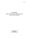
1
January 2013
HARDWARE USER’S MANUAL
RibEye™ Multi-Point Deflection Measurement System
3-Axis Version for the WorldSID 50th ATD
Boxboro Systems LLC
978-257-2219
www.boxborosystems.com
1
© 2013 Boxboro Systems LLC
January 2013
Table of Contents
Page
1.0
2.0
WorldSID RibEye Description ........................................................................................ 5
RibEye Installation ........................................................................................................... 9
2.1 LED and sensor installation...................................................................................... 9
2.1.1. Mounting the LEDs on the ribs..................................................................... 9
2.1.2 Installing the sensors on the spine ............................................................... 18
2.1.3 Order of assembly (LEDs, ribs, and sensors) .............................................. 21
2.2 Controller installation .............................................................................................. 22
2.2.1 Mounting the adaptor plates ........................................................................ 22
2.2.2 Removing the controller end covers ............................................................ 24
2.2.3 Attaching the controller ............................................................................... 25
2.3 Cable routing ........................................................................................................... 26
2.3.1 Status cable .................................................................................................. 26
2.3.2 Dummy exit cable........................................................................................ 26
2.3.3 LED cables................................................................................................... 27
2.3.4 Sensor cables ............................................................................................... 28
3.0 RibEye Operation ............................................................................................................ 32
3.1 Data coordinate systems .......................................................................................... 32
3.2 Status indicator ........................................................................................................ 33
3.3 Ethernet link and activity lights............................................................................... 33
3.4 Batteries and chargers.............................................................................................. 33
3.5 Shoulder foam stop strap ......................................................................................... 36
3.6 Error codes............................................................................................................... 36
4.0 RibEye Maintenance........................................................................................................ 38
Appendices
A. RibEye Specifications......................................................................................................... 39
A-1 Measurement accuracy and range............................................................................. 39
A-2 Power requirements .................................................................................................. 43
A-3 Data acquisition and storage ..................................................................................... 43
A-4 Ethernet communication .......................................................................................... 43
A-5 Trigger circuit ........................................................................................................... 43
B.
RibEye Cables .................................................................................................................... 46
B-1 Dummy exit cable ..................................................................................................... 46
B-2 LED cables................................................................................................................ 46
B-3 Sensor cables............................................................................................................. 46
B-4 Status cable ............................................................................................................... 46
2
© 2013 Boxboro Systems LLC
January 2013
List of Figures
Figure No.
1
2
3
4
5
6
7
8
9
10
11
12
13
14
15
16
17
18
19
20
21
22
23
24
25
26
27
28
29
30
A1
A2
A3
A4
A5
B1
B2
B3
B4
Page
RibEye sensors mounted in the dummy......................................................................5
RibEye LEDs mounted in the dummy ........................................................................6
RibEye controller with connector covers in place ......................................................7
RibEye controller with connector covers removed.....................................................7
Controller sensor connectors.......................................................................................8
Controller connectors for LED cables, status cable, and dummy exit cable...............8
LED and angled mounting block ................................................................................9
LED snapped into angled mounting block.................................................................10
Inner rib clamp plate for thoracic and abdominal ribs ...............................................11
Rearward and forward LED locations .......................................................................13
Rearward LED placed on double-stick tape ..............................................................14
Heat-shrink tubing placed over rearward LED ..........................................................15
Cable routing for rearward and center LEDs .............................................................16
Zip-ties on both sides of inner rib clamp securing the LED cables ...........................17
RibEye sensor bases mounted to spine ......................................................................18
RibEye sensor front piece ..........................................................................................19
RibEye sensor assemblies mounted to spine .............................................................20
Controller adaptor installed on thoracic 1 rib ............................................................22
Controller adaptor installed on abdominal 2 rib ........................................................23
Controller end cover attachment screws ....................................................................24
Controller (sensor connector end) attached to adaptor at thoracic 1 rib ....................25
Controller (cable connector end) attached to adaptor at abdominal 2 rib ..................26
Dummy exit cable ......................................................................................................27
Sensor cables routed to back of dummy ....................................................................28
Sensor cables tied to outer ribs near spine plate ........................................................29
Sensor cables routed over the top sensor and below the neck assembly ...................30
Sensor cables tied to controller ..................................................................................31
Battery packs..............................................................................................................34
RibEye battery pack Cell-Con charger and exit cable charger receptacle .................35
Shoulder foam stop strap ...........................................................................................36
RibEye measurement range in X-Y plane – all ribs...................................................40
RibEye measurement range in Y-Z plane – upper three ribs .....................................41
RibEye measurement range in Y-Z plane – lower three ribs .....................................42
Generic trigger input circuit.......................................................................................44
Trigger input configured for DTS MDB-supplied trigger .........................................45
Dummy exit cable – Microfit connector end details..................................................47
LED cables.................................................................................................................49
Sensor cables..............................................................................................................50
Status cable ................................................................................................................51
3
© 2013 Boxboro Systems LLC
January 2013
List of Tables
Table No.
1
2
3
4
B1
Page
Summary of LED positions and mounting methods..................................................12
Sensor base part numbers and angles.........................................................................19
Nominal LED positions with RibEye mounted on dummy left side .........................33
Cell-Con charger modes ............................................................................................34
Dummy exit cable – Lemo connector pins ................................................................48
4
© 2013 Boxboro Systems LLC
January 2013
HARDWARE USER’S MANUAL
RibEye™ Multi-Point Deflection Measurement System
3-Axis Version for the WorldSID 50th ATD
1.0
WorldSID RibEye Description
The RibEye for the WorldSID anthropomorphic test device (ATD) provides X, Y, and Z position
data for 18 light-emitting diodes (LEDs) mounted on the WorldSID ribs. Three LEDs are
mounted on each of the six ribs. The RibEye for the WorldSID can be mounted on either side of
the dummy to measure left-side or right-side impacts. Appendix A provides the RibEye
measurement range and other specifications.
Up to 25 seconds of data can be collected at a 10-kHz sample rate. Flash memory stores 1.7
seconds of data (from –200 ms to 1500 ms) that is retained after power is turned off. If external
power is lost, the RibEye will operate on internal batteries. Communication to the RibEye is via
Ethernet.
Two sets of three sensors monitor the LED positions, as shown in Figure 1. The top set of
sensors uses red optical filters and monitors the red LEDs mounted on the first three ribs: the
shoulder rib, the thoracic 1 rib, and the thoracic 2 rib. The bottom set of sensors uses blue optical
filters and monitors the blue LEDs mounted on the lower three ribs: the thoracic 3 rib, the
abdominal 1 rib, and the abdominal 2 rib.
Figure 1. RibEye sensors mounted in the dummy
(view from pelvis upward)
5
© 2013 Boxboro Systems LLC
January 2013
Three RibEye LEDs are mounted on each rib. Figure 2 shows the RibEye LEDs installed in the
WorldSID dummy. The center LEDs are lined up along the dummy’s left or right side. The
forward LEDs are closer to the front of the dummy and the rearward LEDs closer to the dummy’s
back.
Figure 2. RibEye LEDs mounted in the dummy
(view from pelvis upward)
The RibEye controller mounts on the non-struck side of the dummy. The controller enclosure
also contains the battery pack for the data acquisition system (DAS) and a second battery pack for
the RibEye. Figures 3–6 show the following views of the controller:
•
Figure 3 shows the controller as shipped, with connector covers installed on the top and
at each end. (Note that the green cable comes from the DAS battery pack.)
•
Figure 4 shows the controller with the two end covers removed.
•
Figure 5 shows the connectors for the sensors at one end of the controller.
•
Figure 6 shows the connectors for the LED cables, status cable, and dummy exit cable at
the other end of the controller.
6
© 2013 Boxboro Systems LLC
January 2013
Figure 3. RibEye controller with connector covers in place
(green cable exiting from DAS battery pack)
Figure 4. RibEye controller with connector covers removed
7
© 2013 Boxboro Systems LLC
January 2013
Figure 5. Controller sensor connectors
Figure 6. Controller connectors for LED cables,
status cable, and dummy exit cable
8
© 2013 Boxboro Systems LLC
January 2013
2.0
RibEye Installation
This section explains how to mount the RibEye components into the WorldSID 50th Male ATD.
The instructions cover the installation of the LEDs, sensors, and controller, as well as the cable
routing. Some components are mounted before the ribs are assembled in the dummy, and others
during or after rib assembly.
2.1
LED and sensor installation
2.1.1 Mounting the LEDs on the ribs
Figure 7 shows a LED assembly, with its lead cable attached, and an angled mounting block. The
LED is soldered onto a metal-clad printed circuit board (MCPCB). Figure 8 shows the LED
assembly snapped into the angled mounting block.
Figure 7. LED and angled mounting block
9
© 2013 Boxboro Systems LLC
January 2013
Figure 8. LED snapped into angled mounting block
The angled mounting blocks are used on four of the dummy’s six ribs – the shoulder, thoracic 2,
thoracic 3, and abdominal 2 ribs. On the shoulder and thoracic 3 ribs, the LEDs are mounted on
the bottom edge of the ribs. On the thoracic 2 and abdominal 2 ribs, the LEDs are mounted on
the top edge of the ribs.
On the dummy’s other two ribs – the thoracic 1 and abdominal 1 – all three LEDs are mounted
flat, without a block.
This becomes more clear if you refer back to Figure 2, which shows three LEDs mounted on each
rib.
10
© 2013 Boxboro Systems LLC
January 2013
The center LEDs on the thoracic and abdominal ribs are mounted to inner rib clamp plates, shown
in Figure 9:
•
Hole A is for installing the angled blocks, which are screwed to the clamp plates using a
¼ inch long, 2-56 screw that engages in a captive 2-56 nut inside the angled blocks.
•
Recess B is for gluing flat LED assemblies to the clamp plate. The clamp plates for the
thoracic 1 and abdominal 1 ribs are shipped with the LED assemblies already glued into
recess B.
•
The two C holes are for mounting a 7264-type accelerometer on any rib.
The clamp plate for the shoulder rib also has holes for mounting the LEDs and the accelerometer.
C
B
A
Figure 9. Inner rib clamp plate for thoracic and abdominal ribs
As noted earlier, the forward LEDs are closer to the front of the dummy and the rearward LEDs
closer to the dummy’s back. These rearward and forward LEDs on all ribs are held in place with
high-strength double-sided foam tape and heat-shrink tubing. The foam tape is 3M #4936 (½
inch wide, VHB acrylic tape). The heat-shrink tubing is either 1½ or 1¼ inches in diameter.
For ribs with angled blocks, use 1½ inch diameter tubing. For LEDs mounted flat on the ribs, use
1¼ inch diameter tubing.
Table 1 summarizes the LED positions and mounting methods for all 18 LEDs.
11
© 2013 Boxboro Systems LLC
January 2013
Table 1. Summary of LED positions and mounting methods
Rib number and type
Rib #1 (shoulder)
Rearward
bottom edge of rib
snap LED assembly to angled block
tape and heat-shrink in place
(1½ inch diameter tubing)
LED position
Center
bottom edge of rib
LED assembly already glued to angled block
screw angled block into clamp plate
Forward
bottom edge of rib
snap LED assembly to angled block
tape and heat-shrink in place
(1½ inch diameter tubing)
Rib #2 (thoracic 1)
center of rib, mounted flat
tape and heat-shrink in place
(1¼ inch diameter tubing)
center of rib, mounted flat
LED assembly already glued to clamp plate
center of rib, mounted flat
tape and heat-shrink in place
(1¼ inch diameter tubing)
Rib #3 (thoracic 2)
top edge of rib
snap LED assembly to angled block
tape and heat-shrink in place
(1½ inch diameter tubing)
top edge of rib
LED assembly already glued to angled block
screw angled block into clamp plate
top edge of rib
snap LED assembly to angled block
tape and heat-shrink in place
(1½ inch diameter tubing)
Rib #4 (thoracic 3)
bottom edge of rib
snap LED assembly to angled block
tape and heat-shrink in place
(1½ inch diameter tubing)
bottom edge of rib
LED assembly already glued to angled block
screw angled block into clamp plate
bottom edge of rib
snap LED assembly to angled block
tape and heat-shrink in place
(1½ inch diameter tubing)
Rib #5 (abdominal 1)
center of rib, mounted flat
tape and heat-shrink in place
(1¼ inch diameter tubing)
center of rib, mounted flat
LED assembly already glued to clamp plate
center of rib, mounted flat
tape and heat-shrink in place
(1¼ inch diameter tubing)
Rib #6 (abdominal 2)
top edge of rib
snap LED assembly to angled block
tape and heat-shrink in place
(1½ inch diameter tubing)
top edge of rib
LED assembly already glued to angled block
screw angled block into clamp plate
top edge of rib
snap LED assembly to angled block
tape and heat-shrink in place
(1½ inch diameter tubing)
NOTE: After rib assembly, nylon zip ties are added around the center LED clamp plates to secure the cables.
12
© 2013 Boxboro Systems LLC
January 2013
The rearward and forward LEDs are typically mounted 50 mm from the center of the rib as
shown in Figure 10. The 50-mm dimension is the straight line distance. This equates to 60 mm
along the curve of the rib.
50 mm
50 mm
Figure 10. Rearward and forward LED locations
As noted earlier, the LEDs must be mounted to the ribs before the ribs are installed in the dummy.
The 18 LED cables are marked with the rib number (1–6) and one of three LED positions as
follows:
Rib #1 (shoulder)
F (Forward) C (Center) R (Rearward)
Rib #2 (thoracic 1)
F
C
R
Rib #3 (thoracic 2)
F
C
R
Rib #4 (thoracic 3)
F
C
R
Rib #5 (abdominal 1)
F
C
R
Rib #6 (abdominal 2)
F
C
R
Thus, for example, the LED with the cable marked 4-R should be mounted on the thoracic 3 rib in
the rearward position.
13
© 2013 Boxboro Systems LLC
January 2013
On each rib, the rearward LEDs should be mounted first, then the center LEDs, and finally the
forward LEDs. The LEDs should be mounted according to the following procedure:
1. Rearward LEDs
Place a strip of double-stick tape on the rib at the rearward LED mounting location. Add a
second piece of tape that will hold the LED cable in position. Place the LED on the first piece of
tape and arrange the cable on the second piece of tape so that the cable avoids the spot where the
center LED will be mounted (see Figure 11).
Figure 11. Rearward LED placed on double-stick tape
14
© 2013 Boxboro Systems LLC
January 2013
Cut a piece of heat-shrink tubing 1½ to 2 inches long and punch a hole in the tubing where the
center of the LED will be (this can be done using a standard paper hole punch or similar tool).
Slide the tubing over the rib and LED as shown in Figure 12. Center the hole directly over the
red dot in the center of the LED.
NOTE: Do not use any glue-lined heat-shrink tubing because the glue can bubble out of the LED
hole and cover the LED, blocking its light.
Figure 12. Heat-shrink tubing placed over rearward LED
Carefully begin shrinking the tubing using a heat gun while holding the hole over the LED.
Start with the areas that are farthest away from the LED, then turn the rib over and shrink the
back side tightly, eliminating bubbles. Return to the inner side and apply heat gently around the
edges of the LED hole, keeping the LED fully exposed, but do not apply too much heat directly to
the LED. You might need to stretch the round hole with your finger so that it fits around the
square edge of the LED. However, do not touch the soft silicone face of the LED with sharp
objects. Figure 13 (right-hand side) shows a rearward LED after the tubing has been heated and
is in place.
Be careful not to burn yourself. It helps to wear a welding glove or other temperature-proof glove
so that you can hold the heat-shrink tubing in place while using the heat gun.
NOTE: It takes a little practice to master the technique of mounting LEDs with heat-shrink
tubing. You can always cut off the tubing and try again.
15
© 2013 Boxboro Systems LLC
January 2013
Figure 13. Cable routing for rearward and center LEDs
2. Center and Forward LEDs
The next step is to install the center LED and route the cables. As noted earlier, the center LEDs
are mounted on the inner rib clamp plates, which either have the LED glued onto them or have
the LED/angled block screwed into them.
Temporarily install the inner rib clamp with LED assembly. Then place the double-stick tape for
the forward LED and route the cables from the center and rearward LEDs as shown in Figure 13
above. Note how the LED cables are routed to avoid crossing in front of any LEDs.
Place the forward LED in position on the double-stick tape and slide a piece of heat-shrink tubing
over the LED. The tubing should also cover all three LED cables. Heat-shrink the tubing over
the forward LED in the same way described above for the rearward LED. When heat-shrinking is
complete, the tubing will hold the LED and the cables in place.
16
© 2013 Boxboro Systems LLC
January 2013
Later, after the rib is assembled into the dummy (see Section 2.1.3 below), nylon zip-ties will be
used on both sides of the inner rib clamp to further secure the LED cables, preventing them from
moving in front of the LEDs. The zip ties are shown in Figure 14.
Figure 14. Zip-ties on both sides of the inner rib clamp securing the LED cables
17
© 2013 Boxboro Systems LLC
January 2013
2.1.2 Installing the sensors on the spine
The RibEye’s sensor assemblies take the place of the existing rib-to-spine clamps. Each sensor
assembly has a front piece that contains the electronics and a base for mounting to the spine. It is
the sensor bases that act as the rib clamps.
Figure 15 shows the sensor bases mounted to the spine. The sensor bases are installed through
the spine’s existing rib-mounting holes using four M5x10 flat-head cap screws. The sensor bases
have different angles depending on the mounting positions (Table 2).
Figure 15. RibEye sensor bases mounted to spine
(ribs not shown)
18
© 2013 Boxboro Systems LLC
January 2013
Table 2. Sensor base part numbers and angles
Rib
Shoulder
Thoracic 1
Thoracic 2
Thoracic 3
Abdominal 1
Abdominal 2
Sensor Base Part Number
10071-11
10071-0
10071-23
10071-20
10071-0
10071-20
Base Angle, degrees
11
0 (flat)
23
20
0 (flat)
20
The sensor front piece containing the electronics (Figure 16) is attached to the sensor base by two
M3x16 flat-head cap screws. Although the sensor front pieces look identical, each piece is
marked with the number of the rib that it was calibrated on, and the sensor front piece must be
installed on that rib. Figure 17 shows the spine with the entire sensor assemblies installed (bases
and front pieces). However, the sensor front pieces are not mounted to their bases until the ribs
are in place inside the dummy (see Section 2.1.3).
Figure 16. RibEye sensor front piece
19
© 2013 Boxboro Systems LLC
January 2013
Figure 17. RibEye sensor assemblies mounted to spine
(ribs not shown)
20
© 2013 Boxboro Systems LLC
January 2013
2.1.3 Order of assembly (LEDs, ribs, and sensors)
1. Mount the LEDs on the ribs.
2. Mount the ribs to the spine as follows:
a. Install the outer ribs first
b. Attach the inner ribs to the outer ribs
c. Attach the inner ribs and sensor bases to the spine.
3. Add nylon zip-ties around the inner and outer ribs on either side of the inner rib clamps.
4. Attach the sensor front pieces to the bases.
Note again that each sensor base number must match the rib where it belongs, and each sensor
front piece must match the rib for which it was calibrated.
21
© 2013 Boxboro Systems LLC
January 2013
2.2
Controller installation
The RibEye controller is installed on the non-struck side of the dummy. In existing WorldSID
dummies, the RibEye controller takes the place of the battery enclosure and tungsten ballast
weight, which are removed.
2.2.1 Mounting the adaptor plates
The controller mounts to two adaptor plates that take the place of the rib clamps on the non-struck
side of the thoracic 1 rib and the abdominal 2 rib (Figures 18 and 19). The adaptor plates are
installed by removing the four rib clamp bolts (M5x10 flat-head cap screws), removing the rib
clamp plates, and then installing the adaptors using the same four M5x10 screws.
Figure 18. Controller adaptor installed on thoracic 1 rib
22
© 2013 Boxboro Systems LLC
January 2013
Figure 19. Controller adaptor installed on abdominal 2 rib
23
© 2013 Boxboro Systems LLC
January 2013
2.2.2 Removing the controller end covers
The controller is shipped with two covers screwed in place, one at each end (shown previously in
Figure 3). The covers protect the connectors for the RibEye sensors on one end (Figure 5) and
the connectors for the LED cables, status cable, and dummy exit cable at the other end (Figure 6).
To install the controller, the two covers must be removed by unscrewing two M3x50 socket-head
cap screws from the top of each cover and two M3x8 socket-head cap screws from the end of
each cover. Figure 20 shows the locations of three of the four cover attachment screws on one of
the covers (the fourth screw is not visible in the photo).
Figure 20. Controller end cover attachment screws
24
© 2013 Boxboro Systems LLC
January 2013
2.2.3 Attaching the controller
When the covers have been removed, slide the controller into the non-struck side of the ribs from
the pelvis end of the dummy. The sensor connector panel should be facing toward the dummy’s
head, and the cable connector panel (connections for LED, status, and dummy exit cables) should
be facing toward the pelvis.
The controller is attached to the two adaptor plates on the ribs using two M5x16 flat-head cap
screws, one at each end, as shown in Figures 21 and 22.
Figure 21. Controller (sensor connector end)
attached to adaptor at thoracic 1 rib
25
© 2013 Boxboro Systems LLC
January 2013
Figure 22. Controller (cable connector end)
attached to adaptor at abdominal 2 rib
2.3
Cable routing
2.3.1 Status cable
First, plug in the status cable at the 2-pole connector at the bottom end of the controller. This
cable is routed to the outside of the dummy so you can see that the RibEye is working and what
state it is in (see Section 3.2).
2.3.2 Dummy exit cable
Next, plug in the dummy exit cable at the 24-pole connector. This cable provides RibEye power,
Ethernet communications, and a trigger signal to the RibEye. The dummy exit cable is routed
outside the dummy, along with the DAS exit cable. Note that the dummy exit cable has the
RibEye battery charger receptacle bundled with it. The dummy exit cable is shown in Figure 23.
The RibEye controller end is a 24-pole Molex Microfit 3 connector. At the external end is a 14pole Lemo 2B connector. The charger receptacle is a 2.5-mm barrel jack. Appendix B provides
more details on all of the cables, including the connector pinouts.
26
© 2013 Boxboro Systems LLC
January 2013
Figure 23. Dummy exit cable
2.3.3 LED cables
Route the rib LED cables between the ribs and over the front of the dummy, under the sternum,
then downward to the bottom end of the controller. The LED cables exit from the six ribs as
follows:
•
Shoulder (rib #1): LED cables exit from the bottom of the rib and goes between the
shoulder rib and the thoracic 1 rib to the non-struck side.
•
Thoracic 1 (rib #2): LED cables exit from the top of the rib and goes between the
shoulder rib and the thoracic 1 rib to the non-struck side.
•
Thoracic 2 (rib #3): LED cables exit from the top of the rib and goes between the
thoracic 1 rib and the thoracic 2 rib to the non-struck side.
•
Thoracic 3 (rib #4): LED cables exit from the bottom of the rib and goes between the
thoracic 2 rib and the thoracic 3 rib to the non-struck side.
•
Abdominal 1 (rib #5): LED cables exit from the bottom of the rib and goes between the
abdominal 1 rib and the abdominal 2 rib to the non-struck side.
•
Abdominal 2 (rib #6): LED cables exit from the top of the rib and goes between the
abdominal 1 rib and the abdominal 2 rib to the non-struck side.
Tie the LED cables together on the non-struck side and tie the cable bundle to the inside of the
ribs along the side of the controller. Then plug the connectors into the LED sockets on the
bottom end of the controller and zip-tie the bundle to one of the cable tie-downs on the end of the
27
© 2013 Boxboro Systems LLC
January 2013
controller. Zip-tie the dummy exit cable and the status cable to the other cable tie-down at the
end of the controller.
After all the LED cables and the dummy exit cable are connected, the cover on the bottom end of
the controller can be re-installed. Two M3x50 socket-head cap screws attach the cover top to the
base. Two M3x8 socket-head cap screws attach the cover at the end of the controller. The cover
screw locations were shown previously in Figure 20.
2.3.4 Sensor cables
Route the sensor cables between the ribs toward back of dummy, as shown in Figure 24. Then
route the cables along the inside of the outer ribs toward the dummy’s head, as shown in Figure
25. Zip-tie the cables to the inside of the outer rib as close to the spine plate as possible.
Figure 24. Sensor cables routed to back of dummy
28
© 2013 Boxboro Systems LLC
January 2013
Figure 25. Sensor cables tied to outer ribs near spine plate
29
© 2013 Boxboro Systems LLC
January 2013
The bundle of sensor cables should go above the top sensor and below the bottom of the neck
assembly, as shown in Figure 26. On the non-struck side, zip-tie the sensor cables to the shoulder
rib, as shown in Figure 27.
Figure 26. Sensor cables routed over the top sensor
and below the neck assembly
30
© 2013 Boxboro Systems LLC
January 2013
Figure 27. Sensor cables tied to controller
Plug the sensor cables into the sensor sockets at the top end of the controller. Plug in the cables
in the following order:
1. Abdominal 2 rib (cable #6)
2. Abdominal 1 rib (cable #5)
3. Thoracic 3 rib (cable #4)
4. Thoracic 2 rib (cable #3)
5. Thoracic 1 rib (cable #2)
6. Shoulder rib (cable #1)
Zip-tie the cables to the cable tie-downs on the end of the controller. Then re-install the cover on
the top end of the controller using two M3x50 socket-head cap screws and two M3x8 socket-head
cap screws.
31
© 2013 Boxboro Systems LLC
January 2013
3.0
RibEye Operation
This section describes the operation, coordinate systems, and connections used in the RibEye.
The RibEye for the WorldSID can be mounted on either side of the dummy to measure left-side
or right-side impacts.
Please refer to the RibEye Software User’s Manual for software details and instructions on how
to change the RibEye network’s IP address (Appendices A–C in the software manual). The
manual is on our website, www.boxborosystems.com.
3.1
Data coordinate systems
As noted earlier, two sets of three sensors monitor the LED positions. The top set of sensors
monitors the red LEDs mounted on the first three ribs (shoulder, thoracic 1, and thoracic 2). The
bottom set of sensors monitors the blue LEDs mounted on the lower three ribs (thoracic 3,
abdominal 1, and abdominal 2).
Position data from each sensor set is reported with respect to a coordinate system that has its
origin in the center (middle) sensor of each set:
•
For the top three ribs, the center of the coordinate system is the center of the inside face
of the lens in the sensor mounted on the thoracic 1 rib. Note that the inside face of the
sensor lens is 2 mm from the outside face of the sensor lens. The X-axis is parallel to the
rib, the Y-axis is perpendicular to the spine plate, and the Z-axis is perpendicular to the
rib.
•
For the lower three ribs, the center of the coordinate system is the center of the inside
face of the lens in the sensor mounted on the abdominal 1 rib. The X, Y, and Z axes are
the same as for the upper sensor set (X parallel to the rib, Y perpendicular to the spine
plate, and Z perpendicular to the rib).
Table 2 shows the nominal positions of the LEDs with the RibEye mounted on the left side of the
dummy. The forward and rearward LEDs might vary slightly from these positions, as they are
mounted with double-stick tape and heat-shrink tubing. The data in Table 2 was collected from a
used set of ribs that had passed the thorax impact tests. A new set of ribs will have larger Y
values, typically from 3 mm to 8 mm larger than shown.
For R&D testing, the LEDs can be placed anywhere within the RibEye’s measurement range (see
Appendix A-1). For example, a user could place nine LEDs on a single rib to show the shape of
the rib.
32
© 2013 Boxboro Systems LLC
January 2013
Table 2. Nominal LED positions with RibEye mounted on dummy left side
LED
Shoulder Rear
Shoulder Center
Shoulder Forward
Thoracic 1 Rear
Thoracic 1 Center
Thoracic 1 Forward
Thoracic 2 Rear
Thoracic 2 Center
Thoracic 2 Forward
Thoracic 3 Rear
Thoracic 3 Center
Thoracic 3 Forward
Abdominal 1 Rear
Abdominal 1 Center
Abdominal 1 Forward
Abdominal 2 Rear
Abdominal 2 Center
Abdominal 1 Forward
3.2
X
–59.0
–28.8
23.8
–45.0
–1.3
45.5
–34.7
6.5
53.7
–61.7
–18.5
21.7
–42.1
–0.7
43.3
–23.1
17.6
60.5
Y
mm
–77.2
–92.3
–77.9
–92.8
–108.0
–94.3
–93.5
–105.5
–93.1
–87.8
–101.4
–88.6
–91.6
–106.7
–89.9
–87.5
–100.8
–86.0
Z
–52.9
–54.6
–60.8
–1.9
–0.9
–2.8
40.1
42.0
47.7
–37.1
–35.5
–36.3
0.5
–1.1
–2.7
35.2
32.3
33.9
Status indicator
The status light flashes at varying rates to indicate that the RibEye is operating and what it is
doing:
•
•
•
•
•
0.5 Hz = idle with data in memory
1.0 Hz = idle with memory erased
2.0 Hz = acquiring data
5.0 Hz = storing data in flash memory
10 Hz = erasing flash memory or downloading data
3.3
Ethernet link and activity lights
There are two lights on the side of the controller below the green DAS battery cable (shown
previously in Figure 4). The green light is the Ethernet link light, and the orange light is the
Ethernet activity light.
3.4
Batteries and chargers
There are two battery packs in the RibEye controller enclosure. They can be accessed by
removing the top cover of the controller. Figure 28 shows the controller with the top cover
removed (and end covers also removed).
The RibEye battery pack is on the left in Figure 28, and the DAS battery pack is on the right. The
DAS battery pack consists of nine AA nickel metal hydride (NiMH) batteries. The DAS battery
cables exit the controller (green cable) to the standard DAS battery connector. Refer to your
DAS documentation for connector and charging information.
33
© 2013 Boxboro Systems LLC
January 2013
Figure 28. Battery packs
The RibEye battery pack consists of 12 AAA NiMH batteries. It is plugged directly into the
controller with a connector under the white nylon spacer. The RibEye batteries are turned on
only when the RibEye is armed or storing collected data to flash memory. They will provide a
minimum of 10 minutes of run-time. Whenever the charger is plugged in, the RibEye will
automatically disconnect the batteries from the RibEye circuits to allow the charger to function
properly, even if the RibEye is armed.
The charger for the RibEye battery pack is a Cell-Con Model 452115-01071-3311. A LED on
the charger indicates its current mode, as shown in Table 3. Figure 29 shows the charger and the
exit cable charger receptacle. Please refer to the Cell-Con Manual, which is supplied with the
charger, for information on safety, operation, maintenance, etc.
Table 3. Cell-Con charger modes
LED Color
Mode
Orange
Battery not connected
Orange
Battery initialization and analysis (7 seconds)
Red
Fast charge
Green with intermittent orange flash
Top-off charge
Green
Trickle charge
Alternating Red-Green
Error
34
© 2013 Boxboro Systems LLC
January 2013
Figure 29. RibEye battery pack Cell-Con charger
and exit cable charger receptacle
35
© 2013 Boxboro Systems LLC
January 2013
3.5
Shoulder foam stop strap
An elastic strap prevents the dummy’s shoulder foam from dropping into the shoulder rib and
blocking the LEDs mounted on the rib. The strap, which is 18 inches long and 1 inch wide, has a
D-ring sewn into it. The strap is looped through the slot on the shoulder rib clamp, goes around
the neck, and secures to itself with Velcro. Figure 30 shows the strap mounted on the dummy.
Figure 30. Shoulder foam stop strap
3.6
Error codes
If the RibEye cannot calculate a LED position, the software will insert error codes in the data. If
an error code occurs, data from all three axes, X, Y, and Z, will be forced to the same error code.
Usually error codes occur when the light from a LED is blocked and cannot reach one of the
sensors. Typically, this results when a loose cable gets between the LED and the sensor. Also, if
the center rib on either set of three ribs compresses significantly more than the upper or lower ribs
of the set, it can block the light from the upper or lower rib LEDs to one of the sensors. Too
much ambient light can also cause the RibEye to generate error codes.
36
© 2013 Boxboro Systems LLC
January 2013
The error codes for each sensor set are as follows:
1. The top sensor is blocked or sees too much ambient light
2. The bottom sensor is blocked or sees too much ambient light
3. Both top and bottom sensors are blocked or see too much ambient light
4. The middle sensor is blocked or sees too much ambient light
5. The middle and top sensors are blocked or see too much ambient light
6. The middle and bottom sensors are blocked or see too much ambient light
7. All three sensors are blocked or see too much ambient light
8. A divide-by-zero condition occurred in the data processing
9. Out of range error.
Note that the error code numbers will be changed if the data is processed to give the relative
motion of each LED by subtracting the pre-event data from each data sample. Also, filtering the
data can mask error codes that occur for a short time.
We recommend that all data be reviewed unfiltered, and as absolute position data, to make sure
that the data contains no error codes. If an error code does occur, the data a few milliseconds
before and after the error condition should be discounted, because something partially blocking a
LED can cause reflections that corrupt the position measurement.
37
© 2013 Boxboro Systems LLC
January 2013
4.0
RibEye Maintenance
The only maintenance required for the RibEye is to keep the sensor lenses clean.
A dirty camera lens will create a fuzzy photo, and smudged eyeglasses will distort vision. The
same holds true for RibEye: If the lenses are not clean, the data will be less accurate.
Make sure that the lenses are clean before each and every test.
If the lenses need to be cleaned, follow this procedure:
1. Blow dust off the lenses with clean, dry air.
2. If there is grease or dirt on the lenses, clean them with eyeglass or camera-lens cleaning
solution and lens cleaning paper or a lens cleaning cloth. You can also use isopropyl
alcohol (70 vol %).
3. Make sure there is no residue from the cleaning solution remaining on the lens.
WARNING: DO NOT USE cotton-tipped swabs like Q-Tips. They leave fibers on the lens.
Note: If you can’t get enough light into the thorax to see the lenses well, you can arm the RibEye
to turn on the LEDs.
DANGER: Do not look directly at the LEDs, as they are very bright.
38
© 2013 Boxboro Systems LLC
January 2013
Appendix A. RibEye Specifications
A-1.
Measurement accuracy and range
The RibEye meets the requirements of SAE J211/1 (July 2007) as a combined sensor and data
acquisition system. It also meets the ISO 6487-2000 specifications.
Figure A1 shows the RibEye measurement range in the X-Y plane for all six ribs. The plot also
shows the LED positions reported by the RibEye for a used set of ribs. Note that a new set of ribs
will have slightly larger Y positions, as noted in Section 3.1.
Figure A2 shows the RibEye measurement range in the Y-Z plane for the upper set of three ribs
(shoulder, thoracic 1, and thoracic 2). The plot also shows the LED positions for all of the upper
three rib LEDs.
Figure A2 shows the RibEye measurement range in the Y-Z plane for the lower set of three ribs
(thoracic 2, abdominal 1, and abdominal 2). The plot also shows the LED positions for each of
the lower three rib LEDs.
The maximum error for the Y and Z data is less than 1 mm, and the maximum X error is less than
1.5 mm.
39
© 2013 Boxboro Systems LLC
January 2013
Figure A1. RibEye measurement range in X-Y plane – all ribs
40
January 2013
Figure A2. RibEye measurement range in Y-Z plane – upper three ribs
41
January 2013
Figure A3. RibEye measurement range in Y-Z plane – lower three ribs
42
January 2013
A-2.
Power requirements
The RibEye can be powered by a high-quality DC voltage source from 12 to 36 Volts. At idle,
the RibEye draws 8 Watts. When collecting data, it draws 12 Watts typically and up to 20 Watts
maximum. If all LEDs were blocked and driven to full power, the RibEye could draw up to
40 Watts.
When the batteries are fully charged, the backup battery pack can power the RibEye while
collecting data for at least 10 minutes. After running the RibEye on batteries for 10 minutes, it
will take about 4 hours to fully recharge the batteries.
The RibEye controller has a self-resetting polymer fuse on its power input. If this fuse ever
opens, it can take up to 4 hours to self-reset.
A-3.
Data acquisition and storage
Data is collected to RAM memory and stored post-test in flash memory.
Sample rate: 10,000 samples per second per LED (10 kHz)
Modes: Linear or circular buffer
Total acquisition time: 25 seconds
Data storage: 25 seconds in RAM, 1.7 seconds in flash (non-volatile)
A-4.
Ethernet communication
Communication between the RibEye and the PC software is via 10/100 MBS Ethernet. The IP
address can be set by the user. (Factory default = 192.168.0.240.)
Please refer to the RibEye Software User’s Manual for software details and instructions on how
to change the RibEye network’s IP address (Appendices A–C in the software manual). The
manual is on our website, www.boxborosystems.com.
The RibEye communicates with the PC software using port 3000. An open protocol is used to
send commands to the RibEye and to receive data. See the RibEye Communications Protocol
document on our website for more information.
A-5.
Trigger circuit
The trigger circuit can be configured for a variety of options including a high-impedance input or
a lower impedance, optically isolated input. Please contact Boxboro Systems for your
requirements. The generic trigger circuit inside the RibEye controller is shown in Figure A4.
Figure A5 shows the trigger input configured for connection to a DTS Mini-Distributor (MDB)
system connector.
43
January 2013
Figure A4. Generic trigger input circuit
44
January 2013
Figure A5. Trigger input configured for DTS MDB-supplied trigger
45
January 2013
Appendix B. RibEye Cables
This section provides information on the following cable assemblies:
•
Dummy exit cable (including battery charger socket)
•
LED cables
•
Sensor cables
•
Status cable.
Molex Microfit 3.0 connectors are used on all of the cable assemblies. The drawings call out the
crimp terminals used for the Microfit connectors. We recommend using a Molex crimp tool
designed for the Microfit 3 series. The current production hand crimp tool is Molex part number
638190000. The extraction tool is Molex part number 11-03-0043.
B-1.
Dummy exit cable
The dummy exit cable connects to a 24-pole Molex Microfit 3 receptacle on the controller. This
cable provides RibEye power, Ethernet communications, and a trigger signal to the RibEye. The
cable can be configured to meet the customer’s requirements. The RibEye has several spare
inputs and outputs that can be programmed for the desired user functionality and for connections
to multiple types of DAS systems.
The configuration described below is for connecting the RibEye to a DTS MDB system connector
for power, trigger, and Ethernet. Figure B1 shows the dummy exit cable. The cable has a 24-pin
Molex Microfit plug on the RibEye end, and a 14-pin Lemo 2b connector at the external end.
The 14-pin Lemo connector plugs into a standard DTS DBX cable to SYSTEM port (DDX)
(5 m), DTS part number 10700-00053.
Figure B1 shows the dummy exit cable with the details of the Microfit end connections.
Table B1 lists the pinouts of the Lemo connector with the DTS signal names.
B-2.
LED cables
Figure B2 shows the LED cables. The three LEDs for each rib go to a single 6-pole connector.
The cables are marked with the rib number and the letters R (rear), C (center), or F (forward).
B-3.
Sensor cables
The sensor cables are detailed in Figure B3.
B4.
Status cable
The status cable is shown in Figure B4.
46
January 2013
Figure B1. Dummy exit cable – Microfit connector end details
47
January 2013
Table B1. Dummy exit cable – Lemo connector pins
48
January 2013
3 pieces of
General Cable C1356.21.01
Black Speaker Cable 24 gauge
6 Pin Microfit
43025-2400
cut to length - see below
Circuit Numbering, view
from mating plug side
F
C
R
6
5
4
3
2
1
3 pairs of cables
Tinned lead to pin 1, 2, 3
Tinned Lead has grooves on insulation
pins 1,2,3 are led cathodes (ground)
pins 4,5,6 are led anodes
pin4 is anode 1 = rear LED
pin5 is anode 2 = middle LED
pin6 is anode 3 = front LED
Female Terminal
43030-0003- reel
43030-0009- bag
20-24 gauge
30 micro-inch gold
LED
Cable lengths for Rear LEDs
subtract 50 mm for center leds
subtract 100 mm for front LEDs
Shoulder = 790 mm
Thorax 1 = 780 mm
Thorax 2 = 740 mm
Thorax 3 = 720 mm
Abdomen 1 = 540 mm
Abdomen 2 = 530 mm
BOXBORO SYSTEMS LLC
Circuit Numbering, view
from Wire side
369 Sargent Road, Boxborough, MA 01719
978-257-2219
WorldSID LED Cables
Rev 0
Figure B2. LED cables
49
Oct 24, 2012
January 2013
mg sensor 7 conductor 30 gauge cable
To WorldSID Sensor Assembly
Microfit (8) #
8 Pin Microfit
43025-0800
1
2
3
4
5
6
7
8
Circuit Numbering, view
from mating plug side
8
7
6
5
4
3
2
1
Circuit Numbering, view
from Wire side
Sensor Board
Name
no connect
out A
com
out B
gnd
control
+5v
-5v
Wire Color
brown
blue
orange
black
yellow
red
green
Note: Shield not connected at microfit connector.
BOXBORO SYSTEMS LLC
Female Terminal
43030-0006- reel
43030-0012- bag
26-30 gauge
30 micro-inch gold
Figure B3. Sensor cables
50
369 Sargent Road, Boxborough, MA 01719
978-257-2219
WorldSID Sensor Cables
Rev 0
Oct 24, 2012
January 2013
Top
Top
Note: Terminal Top faces upwards to top of
receptacle to install
Female Terminal
43030-0003- reel
43030-0009- bag
20-24 gauge
30 micro-inch gold
General Cable C1356.21.01
Black Speaker Cable 24 gauge
or equivalent
3 FEET
LED
Tinned lead to pin 1
Tinned Lead has grooves on insulation
Microfit 3.0 2 circuit 2 row
Receptacle
#43025-0200
BOXBORO SYSTEMS LLC
369 Sargent Road, Boxborough, MA 01719
978-257-2219
Status LED Cable
Rev 0
Figure B4. Status cable
51
December 23, 2011