1
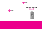
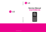
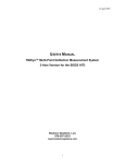
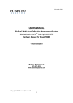
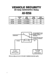
November 2013
HARDWARE USER’S MANUAL
RibEye™ Dual Trunk Box
Boxboro Systems LLC
978-257-2219
www.boxborosystems.com
© 2013 Boxboro Systems LLC
1
November 2013
Table of Contents
Page
Overview .................................................................................................................................. 3
Power Connection .................................................................................................................... 5
Mounting the Trunk Box ......................................................................................................... 5
Cable Assembly
BS-KT-C1 RibEye to MiniDau ........................................................................................ 6
BS-KT-C2 RibEye to KiDau ............................................................................................ 6
Trigger and Power Input Cables .............................................................................................. 7
Power Input Cable ............................................................................................................ 7
Trigger Cable .................................................................................................................... 8
Ethernet Converter and 4-Port Hub ......................................................................................... 9
Appendix A: Setting the RibEye’s IP Address ...................................................................... 10
List of Figures and Tables
Figure No.
Page
1
Dual Trunk Box ......................................................................................................... 3
2
Dual Trunk Box Block Diagram ............................................................................... 4
3
Dual Trunk Box Mounting ........................................................................................ 5
4
BS-KT-C1 Cable Plugged into Dual Trunk Box ....................................................... 6
5
BS-KT-C2 Cable Plugged into Dual Trunk Box ....................................................... 7
6
Power Input Cable from Dual Trunk Box ................................................................. 7
7
Trigger Cable from Dual Trunk Box ......................................................................... 8
8
Trigger Circuit ........................................................................................................... 9
A1
First Screen for Changing the RibEye IP Address ................................................... 10
A2
Configuration Manager Screen ................................................................................. 11
A3
Network Settings Screen .......................................................................................... 11
A4
Confirmation Screen ................................................................................................. 12
Table No.
1
Trigger Cable Wire Colors and Signal Names .......................................................... 8
2
November 2013
Hardware User’s Manual – RibEye™ Dual Trunk Box
Overview
The RibEye Dual Trunk Box connects two RibEye controllers to an Ethernet hub. An Ethernet
converter is connected to the Ethernet hub for converting from a 10Base2 coaxial cable (coax) to
10BaseT (twisted pair).
The Dual Trunk Box (Figure 1) can be connected to a Kistler data acquisition system (DAS),
either a MiniDau or a KiDau. The Kistler DAS provides power, Ethernet communications, and a
Trigger signal to the RibEye controllers via the Dual Trunk Box. Figure 2 shows a block
diagram of the Dual Trunk Box.
Figure 1. Dual Trunk Box
3
November 2013
Figure 2. Dual Trunk Box Block Diagram
10Base2
to
10BaseT
Ethernet Converter
RibEye
Interface
Board #1
4-Port
Ethernet Hub
RibEye
Interface
Board #2
Power
Switch
BNC
Connector
10Base2
Ethernet
RJ45
Connector
10BaseT
Ethernet
Power
Connector
and
Power
LED
Trigger
Connector
RibEye #1
Connector
and
Status LED
RibEye #2
Connector
and
Status LED
The following connectors, LED indicators, and switches are provided:
• MiniDau Connector – This is a coax connector for a 10Base2 Ethernet communication
signal.
• KiDau Connector – This is a standard Ethernet modular jack for a 10/100BaseT Ethernet
communication signal.
• Power Input Connector – This is a two-pole push-pull connector for a power input of
12-36 Volts direct current (VDC). This input provides power to the Dual Trunk Box and
to the two RibEye controllers.
• On/Off Switch – This locking switch turns power on and off to the Dual Trunk Box and
the connected RibEye controllers.
• Power LED – This LED is mounted above the power connector and turns on when power
is applied and when the On/Off switch is in the ON position.
• Trigger Connector – This 8-pole push-pull connector receives a time-zero Trigger signal
from the Kistler DAS or other Trigger source. It is a fully isolated Trigger circuit. In
addition, the connector has a 3.3-V pull-up circuit and ground connections for use with a
passive Trigger switch.
• RibEye #1 and #2 Connectors – These are for the cables to the RibEye controllers for a
5th Female or 50th Male Hybrid III RibEye.
4
November 2013
•
Status LEDs over RibEye Connectors – These LEDs flash at different rates to indicate
what the RibEye is doing. Please refer to the RibEye Hardware User’s Manual for more
information on the Status LEDs.
Power Connection
The Dual Trunk Box can operate on 12-36 VDC input. The nominal voltage is 24 VDC.
Do not exceed 36 VDC input, or equipment will be damaged.
Make sure that the power switch is in the OFF position when making connections to the Dual
Trunk Box. Turn off the Power switch when removing connectors from the Dual Trunk Box.
The electronics in the Dual Trunk Box draw 8 Watts of power (0.33 amps at 24 VDC). Each
RibEye can draw a maximum of 9 Watts, so the total power draw with two RibEyes operating is
up to 26 Watts.
Mounting the Trunk Box
The Dual Trunk Box is provided with M12 sized holes on 75-mm hole spacing. The Dual Trunk
Box should be mounted so that the front face with the connectors is perpendicular to the impact
direction, as shown in Figure 3.
Figure 3. Dual Trunk Box Mounting
(Red Arrow Shows Impact Direction)
5
November 2013
Cable Assembly
BS-KT-C1 RibEye to MiniDau
A BS-KT-C1 cable assembly is used to connect the Dual Trunk Box to a Kistler MiniDau DAS.
Figure 4 shows a BS-KT-C1 cable plugged into the Dual Trunk Box. At one end of the cable is a
BNC connector for 10Base2 Ethernet, a Power plug, and a Trigger plug. At the opposite end is a
Lemo 4B connector that plugs into a MiniDau Interface Out socket. Note that the Ethernet
converter inside the Dual Trunk Box includes a 50-ohm terminator for the 10Base2 Ethernet
connection. When using this cable assembly, set the RibEye Software to use Rising Edge
Trigger.
Figure 4. BS-KT-C1 Cable Plugged into Dual Trunk Box
To MiniDau
Interface Out
Socket
BS-KT-C2 RibEye to KiDau
A BS-KT-C2 cable assembly is used to connect the Dual Trunk Box to a Kistler KiDau DAS.
Figure 5 shows a BS-KT-C2 cable plugged into a Dual Trunk Box. At one end of the cable is an
RJ45 connector for 10BaseT Ethernet, a Power plug, and a Trigger plug. At the opposite end is a
Lemo 4B connector that plugs into a KiDau Interface Out socket. When using this cable
assembly, set the RibEye Software to use Rising Edge Trigger.
6
November 2013
Figure 5. BS-KT-C2 Cable Plugged into Dual Trunk Box
To KiDau
Interface Out
Socket
Trigger and Power Input Cables
One set of Trigger and Power Input cables is provided with the Dual Trunk Box if you wish to
use it independently of a KiDau or MiniDau DAS.
Power Input cable
The Power Input cable from the Dual Trunk Box to the power source is terminated in pigtails at
the user end. The Power Input cable (Figure 6) has two conductors: the red wire (positive) and
the black wire (negative/ground). The red wire is connected to the DC power source’s positive
power connection. The black wire is for the DC power source’s negative (ground) connection.
Figure 6. Power Input Cable from Dual Trunk Box
7
November 2013
Trigger Cable
Figure 7 shows the Dual Trunk Box Trigger cable. Table 1 show the wire colors and signal
names. The Trigger signal is connected to both RibEye #1 and RibEye #2 Trigger circuits, as
shown in Figure 8.
Figure 7. Trigger Cable from Dual Trunk Box
Table 1. Trigger Cable Wire Colors and Signal Names
Wire Color
Connector
Pin Number
Signal
RED
1
3.3-VDC PULL-UP
WHITE
2
TRIGGER IN –
GREEN
3
TRIGGER IN +
ORANGE
4
[reserved]
BROWN
5
[reserved]
BLACK
6
GROUND
YELLOW
7
[reserved]
BLUE
8
[reserved]
8
November 2013
Figure 8. Trigger Circuit
RibEye #1
2
4
1K
VOS628A-3T
1
3
10K
RibEye #2
Trigger Connector
3.3V
249
249
1 - RED
3.3 VDC PULL UP
ZENER
GND
2 - WHITE
2
4
1K
TRIGGER IN-
VOS628A-3T
10K
3 - GREEN
1
3
1N914
TRIGGER IN +
6 - BLACK
GND
GROUND
The 3.3-VDC Pull-Up and Ground connections can be used with an unpowered switch, such as a tape
switch, to provide power for the Trigger circuits.
Ethernet Converter and 4-Port Hub
The 10Base2-to-10BaseT Ethernet converter is a Garrettcom TB14H-24, and the 4-port hub is a
Garrettcom S14H-24. Please refer to the manufacturers’ manuals for these devices for more information.
Electronic copies of these manuals are provided on the RibEye disk, and paper copies are shipped with
the unit.
Note that the TB14-H-24 Ethernet converter has two switches on it:
• A termination switch that is set to 50 ohms for terminating the 10Base2 Ethernet signal.
• A 10BaseT crossover switch that is set to the “straight thru” position.
Both of these switches are locked into position with aluminum tape and should not be changed.
9
November 2013
Appendix A: Setting the RibEye’s IP Address
When the Trunk Box ships from the factory, the IP address of RibEye #1 is set to 192.168.0.240, and the
IP address of RibEye #2 is set to 192.168.0.241. You can change the RibEye IP addresses using a Web
browser. Instructions on how to do this are described below.
NOTE: In order to communicate with the RibEye over a LAN, the RibEye must be on the same subnet as
the LAN. The RibEye’s default IP address of 192.168.0.240 is on the 192.168.0 subnet. If your LAN has
a different subnet, you can connect your PC directly to the Dual Trunk Box via the KiDau Ethernet jack,
and set your PC to a fixed IP address on the 192.168.0 subnet. Instructions for configuring your PC to a
fixed IP address are provided in the RibEye Software User’s Manual (Appendix B-3 for Windows XP and
Appendix C-3 for Windows 7).
How to Change the RibEye’s IP Address
This example assumes that the RibEye address is 192.168.0.240, and that the PC’s IP address is any
address on the 192.168.0 subnet, except 192.168.0.1 or 192.168.0.240.
Launch your Web browser on your PC and go to http://192.168.0.240 for RibEye #1 or
http://192.168.0.241 for RibEye #2. You should see the screen shown in Figure A1.
Figure A1. First Screen for Changing the RibEye IP Address
10
November 2013
Do not enter a user name or password. Just click on the “OK” button and you will be taken to the
Configuration Manager screen (Figure A2).
Figure A2. Configuration Manager Screen
Click on the “Network” selection on the left side of the screen. You will get the Network Settings screen
(Figure A3). Type in your new IP Address for the RibEye in the IP address box. Then click on the “OK”
button. Next click on “Apply Settings” on the left side of the screen.
Figure A3. Network Settings Screen
11
November 2013
After a few moments, you will get the confirmation screen (Figure A4). The RibEye’s IP address is now
changed.
Figure A4. Confirmation Screen
To reconnect to the RibEye, you will have to put the new IP address in your Web browser. If you
changed the IP address to a different subnet than your PC, you will have to change your PC’s IP address
to the new subnet. In most cases, you will change your PC back to having a network-assigned IP address,
and you can plug the RibEye into your LAN.
IMPORTANT: If you change the RibEye IP address, you should write the new IP address
on a sticker and attach the sticker to the RibEye Dual Trunk Box so that the
number is readily available the next time you are using the RibEye.
IMPORTANT: Do not change any other settings, or you will not be able to communicate
with your RibEye.
12