1
4.
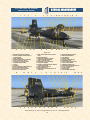
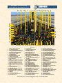
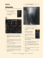
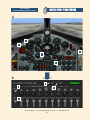
Propellant (helium) source pressure gauge [12, fig.
4-1, 4-2, 4-3; 13, fig. 4-4] – Check (3300 to 3900
psi).
5.
H2O2 source and purge pressure gauge [4, fig. 4-1, 42, 4-3, 4-4] – Check (both pointers, 3300 to 3900
psi).
6.
Propellant tank pressure gauge [6, fig. 4-1, 4-2, 4-3;
81, fig. 4-4] – Check ("L" pointer, 45 to 65 psi;
"A" pointer, 45 to 65 psi).
vice panel;
Chamber pressure will reach rated values;
Thrust chamber will emit a great deal of noise;
Flames and exhaust gases (smoke, steam) will be
seen at the back of the airplane.
ENGINE THRUST CONTROL
7.
H2O2 tank and engine control line pressure gauge
[86, fig. 4-1, 4-2, 4-3; 79, fig. 4-4] – Check (both
pointers, 575 to 615 psi).
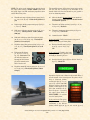
Engine thrust is controlled
by movement of the throttle between 50% and 100%
thrust. Engine response to
throttle movement is very
rapid, 50% to 100% in
approximately 1.5 seconds.
Remember that combustion in the main thrust
chamber of the XLR-99
engine on the X-15 for Flight Simulator will occur almost
instantaneously when the throttle lever [1, fig. 4-9] is
moved from OFF to START 50%.
NORMAL OPERATING CONDITIONS
The following conditions accompany normal rocket engine
operation (see appendix 2 for more details):
XLR-99 engine:
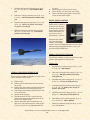
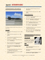
X-15-3 in flight.
NORMAL INDICATIONS DURING START
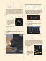
1.
Propellant source pressure gauge [12, fig. 4-1, 4-2, 43; 13, fig. 4-4] – 3200-3800 psi.
2.
H2O2 source and purge pressure gauge [4, fig. 4-1, 42, 4-3, 4-4] – 3000 psi, gradually decreasing
(both pointers).
3.
Propellant tank pressure gauge [6, fig. 4-1, 4-2, 4-3;
81, fig. 4-4] – 45 to 53 psi (both pointers).
4.
Propellant pump inlet pressure gauge [8, fig. 4-2, 43; 74, fig. 4-4] – “L” pointer, 40 to 70 psi; “A”
pointer, 40 to 55 psi.
5.
APU H2O2 tank pressure gauge [64, fig. 4-1, 4-2, 4-3;
66, fig. 4-4] – 550 to 610 psi (both pointers).
6.
Cabin helium source pressure gauge [61, fig. 4-1, 42, 4-3; 59, fig. 4-4] – 1000 to 3400 psi.
7.
Hydraulic temperature gauges [58, 69, fig. 4-1, 4-2,
4-3] – 0° C to 150° C.
When the thrust chamber or chambers are fired, the following indications will be evident:
Turbine whine;
Turbine exhaust steam will be seen at the back of
the aircraft;
Liquid oxygen and ammonia will automatically stop
bleeding overboard (as observed during prime);
Liquid oxygen and ammonia manifold pressure will
rise to rated values;
Igniters will be operating;
Chamber pressure will rise to a point where the
igniters cease firing and chamber pressure will be
shown on the indicator gauge;
Airplane propellants will be consumed at a very
high rate, as can be observed on the volume gauges
[1-3, fig. 4-5] on the X-15 for Flight Simulator ser-
Xtreme Prototypes X-15-2/3 for Flight Simulator, Version 1.0 – Utility Flight Manual
5-25