1
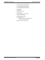
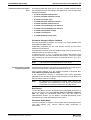
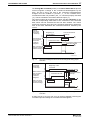
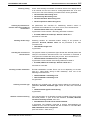
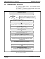
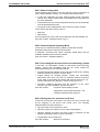
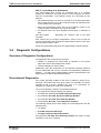
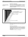
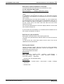
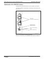
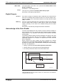
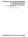
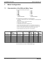
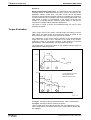
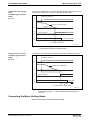
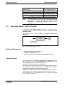
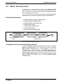
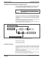
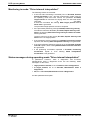
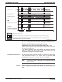
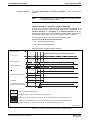
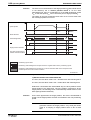
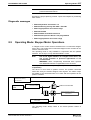
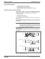
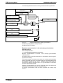
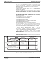
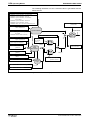
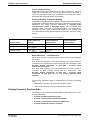
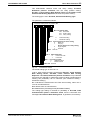
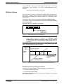
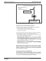
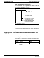
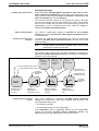
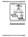
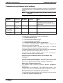
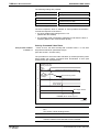
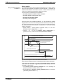
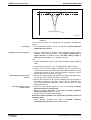
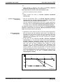
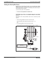
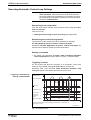
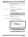
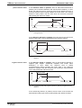
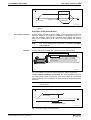
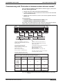
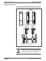
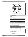
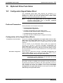
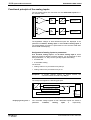
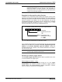
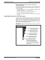
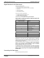
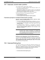
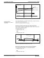
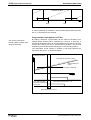
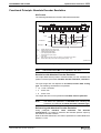
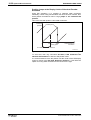
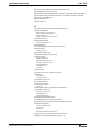
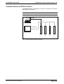
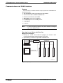
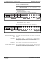
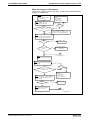
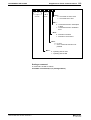
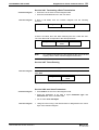
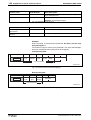
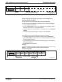
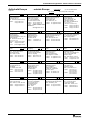
ECODRIVE03 SGP-01VRS
Optional Drive Functions
10-9
31 30 29 282726 252423 2221 2019 1817 1615 1413 1211 10 9 8 7 6 5 4 3 2 1 0
Bit 0..23
24 Bit adress
Bit 28 ..31:
Byteoutput 0x1
Bitoutput 0x2
Fig. 10-6: Parametrizing bit or byte output
scaling
The parameters P-0-0422 Analog output 1, scaling and P-0-0425
Analog output 2, scaling either select the bit to be output or it can be
determined from which (least signifiant) bit on the byte to be generated
will start. When selecting the bit number, only values between 0 and 15
make sense. If greater values are entered, then only bits 0..3 are used.
When outputting bits, -10 volt (bit = 0) or +10 volt ( bit = 1) is output.
Byte output
With byte outputs, the MSB of the byte to be output is interpreted as sign
bit. Voltages ranging from -10 to +10 volts are output.
Terminal assignment - analog output
see project planning manual.
10.4 Analog Inputs
Using the function "Analog inputs", two analog inputs can be used via
analog/digital converters in one parameter each. The analog voltages, in
the form of both of these parameters, can then either be
• transmitted to the control and supports the control as an analog input
function or
• it can be assigned in the drive to a different parameter taking a
settable scaling and a settable offset into account.
Note:
With the help of analog inputs it is also possible to set specific
command values for velocity control mode.
Pertinent Parameters
The following parmeters are available for the function:
• P-0-0210, Analog input 1
• P-0-0211, Analog input 2
• P-0-0212, Analog inputs, IDN list of assignable parameters
• P-0-0213, Analog input 1, Assignment
• P-0-0214, Analog input 1, Scaling per 10V
• P-0-0215, Analog input 2, Assignment
• P-0-0216, Analog input 2, Scaling per 10V
• P-0-0217, Analog input 1, Offset
• P-0-0218, Analog input 2, Offset
DOK-ECODR3-SGP-01VRS**-FKB1-EN-P