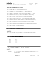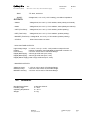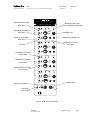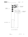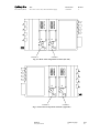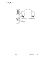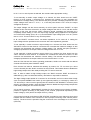
1
Technical
Information
Manual
Revision n. 2
17 October 2005
MOD. N472
4 CH HIGH VOLTAGE POWER SUPPLY MANUAL REV.2
CAEN will repair or replace any product within the guarantee period if the Guarantor declares
that the product is defective due to workmanship or materials and has not been caused by
mishandling, negligence on behalf of the User, accident or any abnormal conditions or
operations.
CAEN declines all responsibility for damages or
injuries caused by an improper use of the Modules due
to negligence on behalf of the User. It is strongly
recommended to read thoroughly the CAEN User's
Manual before any kind of operation.
CAEN reserves the right to change partially or entirely the contents of this Manual at any time
and without giving any notice.
TABLE OF CONTENTS
1.
DESCRIPTION ............................................................................................................................... 4
1.1
2.
SPECIFICATIONS ......................................................................................................................... 5
2.1
2.2
2.3
2.4
2.5
3.
FUNCTIONAL DESCRIPTION............................................................................................... 4
EXTERNAL COMPONENTS.................................................................................................. 5
INTERNAL COMPONENTS ................................................................................................... 6
POWER REQUIREMENTS ..................................................................................................... 6
CHARACTERISTICS OF THE SIGNALS .............................................................................. 6
GENERAL ................................................................................................................................ 7
OPERATING MODES ................................................................................................................. 12
3.1
3.2
3.3
GENERAL INFORMATION ................................................................................................. 12
POLARITY SELECTION....................................................................................................... 12
FRONT PANEL SETTINGS .................................................................................................. 12
LIST OF FIGURES
FIG. 2.1: MOD. N472 FRONT PANEL ....................................................................................................................8
FIG. 2.2: MOD. N472 BACK PANEL ......................................................................................................................9
FIG. 2.3: MOD. N472 COMPONENTS LOCATIONS (LEFT SIDE) .............................................................................10
FIG. 2.4: MOD. N472 COMPONENTS LOCATIONS (RIGHT SIDE) ...........................................................................10
FIG. 2.5: MOD. N472 POLARITY SELECTION (ONE CHANNEL) .............................................................................11
iii
Document type:
User's Manual (MUT)
Title:
N472 4 Ch ± 6kV/1 mA, ±3kV/3mA Power Supply
Revision date:
16/10/2005
Revision:
2
1. DESCRIPTION
1.1
FUNCTIONAL DESCRIPTION
The CAEN Model N472 is a 4 CHANNEL HIGH VOLTAGE POWER SUPPLY housed in a 2unit wide NIM module.
Each module consists of four High Voltage channels; each channel is able to supply an output
Voltage from 0 up to ±3 kV, 3 mA, or up to ±6 kV, 1 mA. The User can change the polarity of
the desired channels by following the simple instructions in paragraph 3.2. The selected
channel polarity is shown by the relevant LEDs on the front panel.
All channels have individual settings and feature test points and a connector for the individual
monitoring of Voltages and Currents. The setting of the output Voltages can be done locally,
via front panel trimmers, or remotely, via analog signals into a front panel connector. The
setting of the output maximum Voltages and Currents can be done only locally, via front panel
trimmers.
Each channel can be switched ON or OFF via front panel switches and can be switched ON
remotely via a TTL low level (or a short circuit connection to Ground) in the relevant
connectors "RON". The H. V. output enable is in common for all channels and can be done via
a front panel switch or via a TTL low level in the relevant connector "DISABLE". This feature
allows to disable the High Voltage output also if the cable providing the TTL level is removed.
A "STATUS" connector for each channel provides a short-circuit-type flag in case of Voltages
or Currents that reach the maximum set.
The module can be powered on either by the NIM crate or with 110 or 220 V AC, via a back
panel Standard European connector.
N. B. If 110 V or 220 V power is selected, the module needs appropriate cooling.
Its wide range of Current and Voltage along with a simple operation and monitoring make it
very useful for powering the full spectrum of detectors used in the modern Physical research,
such as photomultipliers (PMs), wire chambers, streamer tubes and so on. The module is
flexible enough to be adequate both for the lab tests, where simple manual operation of a
limited number of channels is often required, and for a small experimental setup.
The following are the standard Factory settings for the present module:
Channel Polarity:
Negative
MXVSET Trimmer:
6 kV (6 V test point readout)
ISET Trimmer:
1 mA (1 V test point readout)
VSET Trimmer:
0 kV (0 V test point readout)
Filename:
N472_REV2.DOC
Number of pages:
13
Page:
4
Document type:
User's Manual (MUT)
Title:
N472 4 Ch ± 6kV/1 mA, ±3kV/3mA Power Supply
Revision date:
16/10/2005
Revision:
2
2. SPECIFICATIONS
2.1
EXTERNAL COMPONENTS
CONNECTORS
- No. 1, "DISABLE", LEMO 00 type. Connector for the High Voltage outputs ENABLE signal.
- No. 4, "RON", LEMO 00 type, one per channel. Connectors for the REMOTE ON of each
channel.
- No. 4, "RVSET", LEMO 00 type, one per channel. Connectors for the remote Voltage setting
for each channel.
- No. 4, "IMON/VMON", LEMO self-locking round multipin, ERA.0S.302.CNL type, one per
channel. Connectors for the Voltage and Current monitoring for each channel.
- No. 4, "STATUS", LEMO self-locking round multipin, ERA.0S.302.CNL type, one per channel.
Connectors for the status monitoring for each channel.
- No. 4, "1" to "4", High Voltage, SHV R317-580 type. Back panel connectors for the High
Voltage output channels.
- No. 1, Standard European Socket with RF Filter and Fuse, for the Mains power supply.
DISPLAYS
- No. 1, "POWER ON", red LED. It lights up when the Main Power is ON.
- No. 1, "DISABLE", red LED. It lights up when the H. V. output is disabled.
- No. 4, "ON", red LEDs, one per channel. Light up when a H. V. channel is ON.
- No. 4, "POLARITY +", green LEDs, one per channel. Light up when a H. V. channel is in
Positive polarity.
- No. 4, "POLARITY -", yellow LEDs, one per channel. Light up when a H. V. channel is in
Negative polarity.
- No. 4, "MXVSET", red LEDs, one per channel. Light up when a H. V. channel output reaches
the maximum Voltage setting.
- No. 4, "ISET", red LEDs, one per channel. Light up when a H. V. channel output reaches the
maximum Current setting.
- No. 4, "STATUS", red LEDs, one per channel. Light up when a H. V. channel output reaches
the maximum Current or Voltage setting.
Filename:
N472_REV2.DOC
Number of pages:
13
Page:
5
Document type:
User's Manual (MUT)
Title:
N472 4 Ch ± 6kV/1 mA, ±3kV/3mA Power Supply
Revision date:
16/10/2005
Revision:
2
SWITCHES, TRIMMERS, TEST POINTS
- No. 1, "POWER ON", Lever switch, to power ON the module.
- No. 1, "DISABLE", Lever switch, to enable the H. V. output on all channels.
- No. 4, "ON/OFF", Lever switches, one per channel, to switch ON each H. V. channel.
- No. 4, "MXVSET", Trimmers, one per channel, for the Maximum Voltage setting.
- No. 4, "ISET", Trimmers, one per channel, for the Maximum Current setting.
- No. 4, "VSET", Trimmers, one per channel, for the Local Operating Voltage setting.
- No. 4, "MXVSET", Test points, one per channel, for the Maximum Voltage monitoring.
- No. 4, "ISET", Test points, one per channel, for the Maximum Current monitoring.
- No. 4, "VSET", Test points, one per channel, for the Local Operating Voltage monitoring.
- No. 1, "GND", Test point, for the Ground reference.
2.2
INTERNAL COMPONENTS
JUMPERS
- No. 1, "220 / 110 / NIM", 4 pin jumper selector for the module's Main Power selection.
2.3
POWER REQUIREMENTS
220 V
110 V
+24 V
-24 V
2.4
0.6 A
1.2 A
1.6 A
1.6 A
CHARACTERISTICS OF THE SIGNALS
INPUTS:
- DISABLE:
TTL level, active low. Works only when the DISABLE switch is in its
leftmost position.
Filename:
N472_REV2.DOC
Number of pages:
13
Page:
6
Document type:
User's Manual (MUT)
Title:
N472 4 Ch ± 6kV/1 mA, ±3kV/3mA Power Supply
Revision date:
16/10/2005
Revision:
2
- RON:
TTL level, active low.
- RVSET:
Voltage level, -6 to +6 V (1 kV/ V setting), 100 kOhm impedance.
OUTPUTS:
- VMON:
Voltage level, 0 to ±6 V (1 V/ kV readout, same polarity as channel).
- IMON:
Voltage level, 0 to ±3 V (1 V/ mA readout, same polarity as channel).
- VSET (Test Point):
Voltage level, 0 to +6 V (1 V/ kV readout, positive polarity).
- ISET (Test Point):
Voltage level, 0 to +3 V (1 V/ mA readout, positive polarity).
- MXVSET (Test Point): Voltage level, 0 to +6 V (1 V/ kV readout, positive polarity).
- STATUS:
Short Circuit when not active.
- HIGH VOLTAGE OUTPUTS:
High Voltage range: 0 ÷ ±6 kV, 1 mA (0 ÷ ±3 kV, 3 mA) maximum output Current.
Polarity:
positive or negative, User selectable as described in section 3.2.
HV accuracy:
±1% from 10% to 90% of Full Scale Range.
Ripple (NIM supply): ≤30 mV pp at full load (3 kV, 3mA).
Ripple (NIM supply): ≤80 mV pp at full load (6 kV, 1mA).
Ripple (Mains supply):≤150 mV pp at full load (3 kV, 3mA).
- MONITOR OUTPUTS:
VMON accuracy:
IMON accuracy:
MXVSET accuracy:
2.5
± 1% from 10% to 90% of Full Scale Range.
± 2% from 10% to 90% of Full Scale Range.
±1% from 10% to 90% of Full Scale Range.
GENERAL
Max Delivered Power:
Humidity range:
Operating temperature:
Weight:
9 Watt per channel.
0 ÷ 80%.
0 ÷ 45° C.
2.1 Kg.
Filename:
N472_REV2.DOC
Number of pages:
13
Page:
7
Document type:
User's Manual (MUT)
Title:
N472 4 Ch ± 6kV/1 mA, ±3kV/3mA Power Supply
Revision date:
16/10/2005
Revision:
2
Mod. V560E
4 CH HV POWER SUPPLY
MAXIMUM VOLTAGE
SETTING
POLARITY
MAXIMUM CURRENT
SETTING
+
MXVSET
C
H
1
ON
IMON
ISET
OFF
REMOTE CHANNEL ON
VSET
RVSET
STATUS
POLARITY
TEST POINT
+
MXVSET
C
H
2
ON
-
REMOTE VOLTAGE
SETTING
IMON
VMON
OFF
VSET
RVSET
STATUS
POLARITY
+
MXVSET
C
H
3
RON
ON
IMON
VMON
ISET
OFF
OPERATING VOLTAGE
VSET
STATUS
TEST POINT
RVSET
POLARITY
C
H
MXVSET
4
ISET
+
RON
ON
IMON
VMON
OFF
VSET
OUTPUTS ENABLE
GROUND
TEST POINT
RON
ISET
MAXIMUM VOLTAGE
TEST POINT
MAXIMUM CURRENT
CHANNEL ON
VMON
MANUAL VOLTAGE
SETTING
STATUS
REMOTE VOLTAGE
AND CURRENT MONITOR
Mod. N472
GND
STATUS
DISABLE
RVSET
RON
POWER ON
POWER ON
Fig. 2.1: Mod. N472 Front Panel
Filename:
N472_REV2.DOC
Number of pages:
13
Page:
8
Document type:
User's Manual (MUT)
Title:
N472 4 Ch ± 6kV/1 mA, ±3kV/3mA Power Supply
Revision date:
16/10/2005
Revision:
2
1
MAINS SOCKET
AND FUSE
2
CHANNEL
OUTPUTS
3
INPUT POWER
220 AC
4
117 AC
+ 24 DC
NIM
220
110
POWER SUPPLY
SELECTOR
NIM CONNECTOR
Fig. 2.2: Mod. N472 Back Panel
Filename:
N472_REV2.DOC
Number of pages:
13
Page:
9
Document type:
User's Manual (MUT)
Title:
N472 4 Ch ± 6kV/1 mA, ±3kV/3mA Power Supply
-
-
+
+
CHANNEL 3
Revision date:
16/10/2005
Revision:
2
CHANNEL 1
Fig. 2.3: Mod. N472 components locations (left side)
CHANNEL 2
-
-
+
+
CHANNEL 4
Fig. 2.4: Mod. N472 components locations (right side)
Filename:
N472_REV2.DOC
Number of pages:
13
Page:
10
Document type:
User's Manual (MUT)
Title:
N472 4 Ch ± 6kV/1 mA, ±3kV/3mA Power Supply
Revision date:
16/10/2005
Revision:
2
-
+
+
-
POSITIVE POLARITY
NEGATIVE POLARITY
TRANSFORMER
Fig. 2.5: Mod. N472 polarity selection (one channel)
Filename:
N472_REV2.DOC
Number of pages:
13
Page:
11
Document type:
User's Manual (MUT)
Title:
N472 4 Ch ± 6kV/1 mA, ±3kV/3mA Power Supply
Revision date:
16/10/2005
Revision:
2
3. OPERATING MODES
3.1
GENERAL INFORMATION
Each module consists of four High Voltage channels; each channel is able to supply an output
Voltage from 0 up to ±6 kV, 1 mA. The User can change the polarity of the desired channels by
following the simple instructions in the following Section. The selected channel polarity is
shown by the relevant LEDs on the front panel.
3.2
POLARITY SELECTION
The Model N472 allows the User to select the High-Voltage polarity with simple operations that
are detailed in this Section. Note that the polarity is indicated by two LEDs for each channel on
the front panel.
1. In order to change polarity, switch off the unit, remove the Mains plug and all the High
Voltage cables and wait for the complete discharge of the capacitors, then remove the side
covers thereby making access to the Printed Circuit Boards.
WARNING! Any attempt to operate inside the Module without
turning OFF, unplugging all plugs and cables and waiting for 5
minutes, can be lethal.
2. Lay down the unit, NIM crate connector on the right and the front panel on the left, and refer
to Fig. 2.3. The High-Voltage block houses two of the four multipliers of the channels (CH3 and
CH1) and bears a "High-Voltage Danger" label. The cover of each multiplier is fixed to the
base through two screws; remove the screws and the cover. The multiplier will appear as
shown in Fig. 2.3 (for the polarity selection of channels CH2 and CH4 lay down the unit, NIM
crate connector on the left and the front panel on the right as in Fig. 2.4, and follow the
instructions hereafter). The multiplier base is accessible to the User. The front panel
"POLARITY" LEDs indicate the correct polarity for each channel. Remove the multiplier base,
rotate it by 180° and insert it back in its position.
3. Configure the unit to satisfy your requirements: if desired, it is possible to mix positive and
negative channels in the same unit. If the polarity of one or more channels must be changed,
extract the base from its contacts and insert it in the opposite position.
4. Reassemble the unit.
3.3
FRONT PANEL SETTINGS
The module can be powered on either by the NIM crate or with 110 or 220 V AC, via a back
panel Standard European connector. The Mains supply selection can be done by means of a
10 pin jumper located on the internal side of the back panel: this jumper can be accessed by
removing the side cover. A window in the back panel shows the selected power supply.
Once the User has selected the desired polarity of the channels and the Mains supply, the
module can be powered ON via the POWER ON switch. A red LED will be lit when the Power
is ON.
Filename:
N472_REV2.DOC
Number of pages:
13
Page:
12
Document type:
User's Manual (MUT)
Title:
N472 4 Ch ± 6kV/1 mA, ±3kV/3mA Power Supply
Revision date:
16/10/2005
Revision:
2
N. B. If 110 V or 220 V power is selected, the module needs appropriate cooling.
To set manually a certain output Voltage on a channel, the User should turn the "VSET"
trimmer for that channel: a clockwise turn increases the Voltage, an anti clockwise turn
decreases the Voltage setting. The relevant test point provides a Voltage proportional to the
output Voltage at the rate of 1 V/ kV, i. e., if the test point shows a 2.9 V level, the output
Voltage will be 2.9 kV.
The output Voltage can also be set remotely via a front panel connector "RVSET": an input
Voltage on this connector will result in an output Voltage at the rate of 1 kV/V, with the chosen
polarity. In this case, the trimmer "VSET" should be turned completely anti clockwise for a
completely remote setting. In fact, the output High Voltage setting depends on the algebraic
sum of the VSET setting (from 0 to +6 V) and the RVSET input Voltage (from -6 to +6 V) at the
rate of 1 kV/V. This sum MUST in any case be positive.
N. B.: the "RVSET" connector has a 100 kOhm impedance, so for correct H. V. setting the
input Voltage must be provided to this connector with a low impedance generator.
To set manually a certain maximum output Voltage on a channel, the User should turn the
"MXVSET" trimmer for that channel: a clockwise turn increases the maximum Voltage, an anti
clockwise turn decreases the maximum Voltage setting. The relevant test point provides a
Voltage proportional to the output maximum Voltage at the rate of 1 V/ kV.
To set manually a certain maximum output Current on a channel, the User should turn the
"ISET" trimmer for that channel: a clockwise turn increases the maximum Current, an anti
clockwise turn decreases the maximum Current setting. The relevant test point provides a
Voltage proportional to the output maximum Current at the rate of 1 V/ mA.
After the User has set the chosen operating parameters, He/She can switch ON the desired
channel with the front panel "ON/OFF" switch.
Each channel can also be switched ON remotely by means of a TTL low level (or a short
circuit to Ground) into the "RON" connector for that channel. This feature allows to disable the
High Voltage output also if the cable providing the TTL level is removed.
N.B.: In order to obtain a High Voltage output, the "RON" connector MUST be shorted to
GROUND (e.g. with a 50 Ohm termination), otherwise no output will be obtained.
The High Voltage output enable is in common for all channels, and can be done either locally
via a front panel DISABLE lever switch (in the rightmost position), or remotely by means of a
TTL low level (or a short circuit to ground) into the contacts of the "DISABLE" connector (lever
switch in the leftmost position). Also this feature allows to disable the High Voltage output also
if the cable providing the TTL level is removed.
A front panel connector, "IMON/VMON" provides for each channel two monitoring Voltages,
positive or negative according to the polarity of the channel, proportional respectively to the
output Voltage (1 V/kV) and to the output Current (1 V/mA).
A front panel connector and relevant LED "STATUS" provides for each channel a short-circuit
between the two contacts of the connector in case of proper functioning of the channel (LED is
NOT lit). The short-circuit is opened to flag the occurrence of an overvoltage or an overcurrent
(LED is lit).
Filename:
N472_REV2.DOC
Number of pages:
13
Page:
13