1
Document type:
User's Manual (MUT)
Title:
N472 4 Ch ± 6kV/1 mA, ±3kV/3mA Power Supply
Revision date:
16/10/2005
Revision:
2
3. OPERATING MODES
3.1
GENERAL INFORMATION
Each module consists of four High Voltage channels; each channel is able to supply an output
Voltage from 0 up to ±6 kV, 1 mA. The User can change the polarity of the desired channels by
following the simple instructions in the following Section. The selected channel polarity is
shown by the relevant LEDs on the front panel.
3.2
POLARITY SELECTION
The Model N472 allows the User to select the High-Voltage polarity with simple operations that
are detailed in this Section. Note that the polarity is indicated by two LEDs for each channel on
the front panel.
1. In order to change polarity, switch off the unit, remove the Mains plug and all the High
Voltage cables and wait for the complete discharge of the capacitors, then remove the side
covers thereby making access to the Printed Circuit Boards.
WARNING! Any attempt to operate inside the Module without
turning OFF, unplugging all plugs and cables and waiting for 5
minutes, can be lethal.
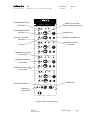
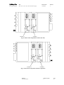
2. Lay down the unit, NIM crate connector on the right and the front panel on the left, and refer
to Fig. 2.3. The High-Voltage block houses two of the four multipliers of the channels (CH3 and
CH1) and bears a "High-Voltage Danger" label. The cover of each multiplier is fixed to the
base through two screws; remove the screws and the cover. The multiplier will appear as
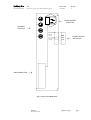
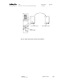
shown in Fig. 2.3 (for the polarity selection of channels CH2 and CH4 lay down the unit, NIM
crate connector on the left and the front panel on the right as in Fig. 2.4, and follow the
instructions hereafter). The multiplier base is accessible to the User. The front panel
"POLARITY" LEDs indicate the correct polarity for each channel. Remove the multiplier base,
rotate it by 180° and insert it back in its position.
3. Configure the unit to satisfy your requirements: if desired, it is possible to mix positive and
negative channels in the same unit. If the polarity of one or more channels must be changed,
extract the base from its contacts and insert it in the opposite position.
4. Reassemble the unit.
3.3
FRONT PANEL SETTINGS
The module can be powered on either by the NIM crate or with 110 or 220 V AC, via a back
panel Standard European connector. The Mains supply selection can be done by means of a
10 pin jumper located on the internal side of the back panel: this jumper can be accessed by
removing the side cover. A window in the back panel shows the selected power supply.
Once the User has selected the desired polarity of the channels and the Mains supply, the
module can be powered ON via the POWER ON switch. A red LED will be lit when the Power
is ON.
Filename:
N472_REV2.DOC
Number of pages:
13
Page:
12