1
18-1117-50_AC.qxd
1998-10-30 12:19
Sida 1 (1,1)
Autosampler
A-900
User Manual
18-1117-50
18-1117-50_AC.qxd
1998-10-30 12:19
Sida 2 (1,1)
Important user information
!
Meaning: Consult the instruction manual to avoid
personal injury or damage to the product or other
equipment.
Trademarks
ÄKTA and UNICORN are trademarks of Amersham
Pharmacia Biotech Limited or its subsidiaries.
Amersham is a trademark of Nycomed Amersham plc.
Pharmacia and Drop Design are trademarks of
Pharmacia & Upjohn Inc.
WARNING!
The Warning sign is used to call attention to the
necessity to follow an instruction in detail to avoid
personal injury. Be sure not to proceed until the
instructions are clearly understood and all stated
conditions are met.
CAUTION!
The Caution sign is used to call attention to
instructions or conditions that shall be followed to
avoid damage to the product or other equipment. Be
sure not to proceed until the instructions are clearly
understood and all stated conditions are met.
Note
The Note sign is used to indicate information
important for trouble-free or optimal use of the
product.
Should you have any comments on this instruction, we
will be pleased to receive them at:
Amersham Pharmacia Biotech AB
SE–751 84 Uppsala
Sweden
Terms and Conditions of Sale
All goods and services are sold subject to the terms
and conditions of sale of the company within the
Amersham Pharmacia Biotech group which supplies
them. A copy of these terms and conditions of sale is
available on request.
Adresses
Amersham Pharmacia Biotech UK Limited
Amersham Place
Little Chalfont
Buckinghamshire
England HP7 9NA
Amersham Pharmacia Biotech AB
SE-751 84 Uppsala
Sweden
Amersham Pharmacia Biotech Inc
800 Centennial Avenue
PO Box 1327
Piscataway
NJ 08855 USA
© Amersham Pharmacia Biotech AB 1998
– All rights reserved
18-1117-50_AC.qxd
1998-10-30 12:19
Sida i (1,1)
Contents
Contents
1
Introduction
1.1
1.2
1.3
2
Installation
2.1
2.2
2.3
2.4
2.5
3
General ..................................................................................................................9
Maintenance
4.1
4.2
4.3
4.4
4.5
5
Unpacking..............................................................................................................2
Locating the A-900 ................................................................................................3
Power connections .................................................................................................3
Fluid connections ...................................................................................................4
Preparation of vials................................................................................................7
Operation
3.1
4
General ..................................................................................................................1
Safety .....................................................................................................................1
Safety symbols on the A-900 .................................................................................1
Injection valve......................................................................................................11
Needle and tubing................................................................................................14
Syringe, sample loop and buffer tubing combinations .........................................15
Replacing the sample needle ................................................................................17
Syringe .................................................................................................................18
Trouble shooting
5.1
Faults and actions ................................................................................................19
Reference information
A
B
C
Description ..........................................................................................................21
A.1 General .....................................................................................................21
A.2 Instrument.................................................................................................22
A.3 Flushed loop injections..............................................................................24
A.4 Partial loopfill injections ..........................................................................26
A.5 µl pick-up injections..................................................................................28
Technical specifications .......................................................................................30
Accessories and consumables ...............................................................................32
Autosampler A-900
User Manual 18-1117-50 Edition AB
i
18-1117-50_AC.qxd
1998-10-30 12:19
Sida ii (1,1)
Contents
About this manual
This manual comprises two parts; a practical part (sections 1 – 5)
and a reference part (sections A – C).
Sections 1 – 5 contain information for operating the instrument.
ii
Autosampler A-900
User Manual 18-1117-50 Edition AC
18-1117-50_AC.qxd
1998-10-30 12:19
Sida 1 (1,1)
Introduction
1
1 Introduction
1.1 General
Autosampler A-900 is an automated sampling injector for use, with
ÄKTA™ explorer and ÄKTApurifier in liquid chromatography.
The A-900 features:
• Sample injection from a few microlitres to 1 ml
• Three different methods for injection
• Biocompatibility
• Different sizes of sample vials
1.2 Safety
• The instrument is for indoor use only.
• Do not use in a dusty atmosphere or close to spraying water.
• Do not block the air inlet and outlet of the unit.
WARNING! Do not operate the A-900 with the front cover open.
WARNING! Always disconnect the power supply before
attempting to replace any item on the instrument
WARNING! The instrument must not be opened by the user. It
contains high voltage circuits that can deliver a lethal electric
shock.
WARNING! For continued protection against risk of fire, replace
only with fuses of specified type and rating. See Technical
specifications for fuse data.
1.3 Safety symbols on the A-900
The A-900 contains the following safety symbol:
!
SHARP NEEDLE
AND MOVING PARTS
KEEP HANDS CLEAR
This sticker denotes the proximity of the sharp needle and the
moving needle arm of the A-900, which, if not handled with care,
could result in injury or damage or destruction of these parts.
Auto Sampler A-900
User Manual 18-1117-50 Edition AC
1
18-1117-50_AC.qxd
1998-10-30 12:19
Sida 2 (1,1)
2 Installation
2 Installation
2.1 Unpacking
Unpack the instrument and check the items against the supplied
packing list. Inspect the items for obvious damage that may have
occurred during transportation.
Keep all packing materials if onward transport of the instrument is
expected.
Note: Do NOT lift the instrument by the front cover!
Lift the A-900 with both hands under the instrument or with one
hand under the front and the other hand grasping the rear top (see
figure below).
Front cover
locking screw.
Remove to open
front cover.
2
Auto Sampler A-900
User Manual 18-1117-50 Edition AC
18-1117-50_AC.qxd
1998-10-30 12:19
Sida 3 (1,1)
Installation
2
2.2 Locating the A-900
The A–900 needs approximately 28 cm of bench space and a mains
connection of 220-240 V or 100-120 V, 50/60 Hz, preferably taken
from the ÄKTA system base platform.
Be sure that none of the ventilation holes are blocked. Blockage of
the ventilation holes can cause malfunctioning of the A–900
Autosampler or even damage the electronics.
Do not install the A–900 in areas subject to excessive dust, direct
sunlight or shocks, and do not place it near a source of heat.
2.3 Power connections
Before connecting the mains cord to your ÄKTA separation unit,
check that the voltage setting of the A-900 matches the local mains
supply voltage and main fuses. Use only a supply appliance with
protective grounding.
If the indicated voltage is not correct, select the proper voltage by
removing, inverting, and then reinserting the voltage selectorcartridge. Check that the right fuses are installed. If not replace them
with the fuses stated below:
• For 110-120 VAC, use two 5 AT-fuses (slow).
• For 220-240 VAC, use two 2.5 AT-fuses (slow).
.WARNING! For continued protection against risk of fire, replace
only with fuses of specified type and rating. See Technical
specifications for fuse data.
When the voltage selection and fuses are correct for your power
source, plug in the power cord in a free outlet in the base platform
of your ÄKTA separation unit.
Auto Sampler A-900
User Manual 18-1117-50 Edition AC
3
18-1117-50_AC.qxd
1998-10-30 12:19
Sida 4 (1,1)
2 Installation
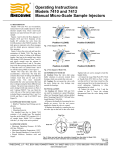
2.4 Fluid connections
The A-900 is factory installed with a 250 µl syringe, a 100 µl PEEK
loop, a 500 µl buffer tubing and a PEEK sample needle.
A schematic presentation of all parts that have contact with fluid is
shown below.
To get access to the fluid parts, it is necessary to open the front
cover of the A-900, therefore remove the screw on the right-hand
side of the cover. The table below lists the dimensions of the
standard installed tubing.
For optimal performance of the A-900, a correct combination of
syringe, loop and buffer tubing should be installed.
Loop
Pump
2
Dispenser
3
Needle
WASTE
WASH
BOTTLE
1
INJECTION
VALVE
4
6
Column
5
INJECT position
LOAD position
Tubing
Standard sample needle tubing
(Volume: 15 µl)
Buffer tubing from high
pressure valve to syringe valve
(Volume: 500 µl)
Tubing, syringe valve to wash
solvent bottle
Tubing, syringe valve to waste
solvent bottle
100 µlPEEK loop
Tubing, general waste
4
Material
PEEK
Dimensions
135 mm x 0.5 mm OD x 0.25 mm ID
Tefzel
640 mm x 1/16” OD x 1.0 mm ID
Tefzel
300 mm x 1/16” OD x 1.0 mm ID
Tefzel
PEEK
Silicon
400 mm x 1/16” OD x 1.6 mm ID
1/16” OD x 0.5 mm ID
2 x 1.2 m, 10 mm OD x 7 mm ID
Auto Sampler A-900
User Manual 18-1117-50 Edition AC
18-1117-50_AC.qxd
1998-10-30 12:19
Sida 5 (1,1)
Installation
2
ÄKTA connections
To ensure reproducible injections, make the connections to your
ÄKTA chromatography system according to the installation
instructions, given in the User Manual included in the XT upgrade
kit for your ÄKTA chromatography system
The A-900 has been flushed with Iso–propanol: make sure that the
mobile phase of your ÄKTA chromatography system is miscible with
iso–propanol. If not, start-up with an intermediate solvent as mobile
phase (disconnect the column).
CAUTION! It is essential that the contents of the sample loop are
injected in back flush onto the column. Therefore:, do not
exchange column and pump connections at the injection valve.
Waste tubing
General waste:
Syringe Waste
Connect the supplied drain tubing to the righthand drain hose connector of the A–900 and put
the other end in a bottle placed on the floor. This
drain removes all the liquid dispensed into the
wash position.
Note: Sample that is not injected is also removed
through this tubing.
Syringe waste:
Condensed
water and
leakage
Drain wash
position
Place the syringe waste tubing in a small bottle
below the A–900. If injection volumes no larger
than the volume of the buffer tubing are
programmed, the syringe waste will only be wash
solvent.
Leakage drain:
All leakage solvents are drained through the lefthand hose connector.
CAUTION! Make sure that the drain and waste
tubings are not twisted and obstructing the flow
path.
Auto Sampler A-900
User Manual 18-1117-50 Edition AC
5
18-1117-50_AC.qxd
1998-10-30 12:20
Sida 6 (1,1)
2 Installation
Wash solvent
The A-900 has a built-in wash solvent reservoir of
250 ml.
To position the wash solvent bottle:
• Fill the wash solvent bottle with the appropriate
wash solvent.
Note: Use methanol or a mixture of one part isopropanol in four parts of water as wash solvent.
Before using the wash solvent, degas the solvent
with Helium or an ultrasonic bath.
• Screw the bottle in the wash solvent holder and
place the holder on the A-900.
• Put the wash solvent tubing in the wash solvent
bottle.
Inj. valve
Wash solvent
Syringe waste
• Fill the tubing using the AutosamplerControl:
SyringeEndand SyringeHomecommands in
Manual:Flowpath.
SyringeEnd aspirates a syringe volume of wash
solvent from the wash solvent bottle and fills the
wash solvent tubing.
SyringeHome dispences the syringe contents to
the syringe waste. Repeat this action until the wash
solvent tubing and the syringe are completely
filled.
After the wash solvent tubing and the syringe are filled, use the
AutosamplerControl: InitialWash command in Manual:Flowpath
to perform a standard wash. All tubing connected to the syringe
valve will be filled and flushed with wash solvent.
The wash solvent bottle is now ready for use.
If you have an application that requires more than 250 ml of wash
solvent for a complete run, you can replace the wash solvent tubing
by a longer tubing with one end flanged for the valve fitting and
place a larger bottle outside the A-900. To fill this wash solvent
tubing, repeat the previous fill procedure a few times.
6
Auto Sampler A-900
User Manual 18-1117-50 Edition AC
18-1117-50_AC.qxd
1998-10-30 12:20
Sida 7 (1,1)
Installation
2
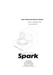
2.5 Preparation of vials
Vial dimensions
The A-900 is very flexible in the use of vials and septa. Almost every
type of vial with an OD of 12 or 7 mm can be used from micro vials
(0.5 ml) to standard vials (1 ml). By using inserts, the vial volumes
of standard vials can be reduced.
To hold all types
of vials, the A-900
can be equipped
with two types of
tray segments,
each for vials with
a specific diameter
(see figure).
12 9
11 8
10
7
6
5
4
3
2
1
A1
A
20 16
19
18 15
17 14
13
12 8 43
11 7 2
10 6 1
9 5 D1
D
Vials used should have the following dimensions:
Maximum vial height, including cap:
Minimum vial height, including cap:
Maximum vial diameter:
Standard vial
Micro vial
Auto Sampler A-900
User Manual 18-1117-50 Edition AC
47 mm
32 mm
12 mm
7 mm
7
18-1117-50_AC.qxd
1998-10-30 12:20
Sida 8 (1,1)
2 Installation
Filling and sealing the vials
The standard vials, as well as the conical vials, can best be filled by a
narrow–end pipette to allow air to escape when filling the vial.
Do not fill vials to the edge! If you do, sample will be forced into the
air needle, risking extra cross-contamination of samples and fouling
of the needle pair.
It is important that the seal is airtight. This maintains a pressure on
the vial that prevents air bubbles and to stop evaporation of volatile
samples.
CAUTION! Do not re-use a sample vial without replacing its cap
or septum.
Note: Check the seal after crimping. If the cap can be turned easily,
the seal is not airtight (re-adjust hand crimper). The seal must not be
deformed after crimping, since this may also deform the needle.
Loading the sample tray
The tray segment types used must be entered in System Settings.
It is not necessary that all segments are available on the tray at the
start of a run.
To place a segment on the tray, there must be an open position in
the front half of the tray. The tray can be rotated if the A-900 is not
running by using the AutosamplerControl:RotateTray command
in Manual:Flowpath. Place the tray segment on the front half of
the tray.
CAUTION! Do not place or remove a tray segment at the rear
half of the A–900 tray. This may damage the tray sensors.
8
Auto Sampler A-900
User Manual 18-1117-50 Edition AC
18-1117-50_AC.qxd
1998-10-30 12:20
Sida 9 (1,1)
Operation
3
3 Operation
3.1 General
• Switch on/off the A-900 using the mains switch located above the
mains inlet on the rear panel.
• The A-900 is operated from UNICORN™ control system.
Operating instructions for the A-900 from UNICORN control
system is described in a separate User Manual included in the XT
upgrade kit for your ÄKTA chromatography system.
• When a 500 µl or 1000 µl syringe is used, the
AutosamplerSyringSpeed command should be set to LOW in
UNICORN System Settings:Special.
• If samples of high viscosity (5-10 cP) is used, the
AutosamplerSyringSpeed command should be set to LOW, and
the Scaling parameter to 0.2 in UNICOR System
Settings:Special.
• Always run the A-900 with the front cover folded down.
• Never open the front cover unless the A-900 is in idle mode.
Auto Sampler A-900
User Manual 18-1117-50 Edition AC
9
18-1117-50_AC.qxd
1998-10-30 12:20
Sida 10 (1,1)
3 Operation
10
Auto Sampler A-900
User Manual 18-1117-50 Edition AC
18-1117-50_AC.qxd
1998-10-30 12:20
Sida 11 (1,1)
Maintenance
4
4 Maintenance
4.1 Injection valve
Description
The Injection valve is a
two position, six port
valve. The figure shows
the flow diagram of the
valve.
The six small circles
represent the ports in
the rotor seal. Rotating
the valve 60° switches
the valve from one
position to another.
2
2
1
1
3
3
6
6
4
5
Shaft assembly
rotated clockwise
4
5
Shaft assembly
rotated counterclockwise
Specifications
• Maximum temperature is 50°C
• The valve withstands 34.5 MPa (5000 psi)
• Wetted surfaces are PEEK, alumina ceramic, and an inert
polymer.
CAUTION! Use only plastic ferrules in the PEEK stator ports.
Metal ferrules can cause irreparable damage to the plastic stator.
WARNING! Do not operate the A-900 with the front cover open.
Auto Sampler A-900
User Manual 18-1117-50 Edition AC
11
18-1117-50_AC.qxd
1998-10-30 12:20
Sida 12 (1,1)
4 Maintenance
Maintenance
With normal use, the valve will give many tens of thousands of
cycles of trouble-free operation. The main cause of early failure,
which is seen as a leak in the valve, is abrasive particles in the
sample and/or mobile phase scratching the rotor seal.
The procedure for changing the rotor seal, stator face
assembly, and isolation seal is as follows. Refer to the
figure and proceed:
Body
a) Remove the three stator screws with a 9/64 inch
hex key.
Shaft assembly
b) Remove the stator, stator face assembly and
stator ring from the valve body.
Isolation seal
c) Pull the rotor seal off the pins.
Rotor seal
d) Remove the isolation seal.
e) Mount the new isolation seal with the spring side
Body locating pin
facing away from the rotor seal.
f)
Mount
the new rotor seal. The three pins on the shaft
Stator ring
assembly fit into the mating holes in the rotor seal
Stator locating pin
only one way. Mount the seal with the grooves facing
the stator.
Stator face assembly g) Replace the stator ring so that the body locating pin
in the stator ring enters the mating hole in the body.
Stator
h) Put the new stator face assembly on the stator. The
three pins on the assembly fit the mating holes in the
Stator support ring
stator only one way.
(PEEK version only)
i) Mount the stator and stator face assembly on the
Stator screws (3)
valve so the stator locating pin in the stator ring
enters the mating hole in the stator.
j) Replace the three stator screws. Tighten each an
equal amount until the screws are tight.
Operating suggestions
CAUTION! Never operate the injection valve when it is dry. This
will reduce the lifetime of the injection valve and probably cause
malfunction.
CAUTION! Never leave the A-900 for more than one day with
buffer solution in the tubings. Rinse the A-900 with distilled water
prior to longer stops.
Aqueous buffers or salt solutions
Prevent the formation of salt crystals in the valve by flushing out the
flow passages and needle port with water after using salt solutions.
Formation of salt crystals may otherwise damage the injection valve.
12
Auto Sampler A-900
User Manual 18-1117-50 Edition AC
18-1117-50_AC.qxd
1998-10-30 12:20
Sida 13 (1,1)
Maintenance
4
Calibrating sample loops
Sample loop sizes are designated by nominal values that can vary
from the actual value by as much as 20%. This variation is due to
the tolerance of the tubing ID. Since standards and unknowns are
usually analyzed with the same loop, knowledge of absolute loop
volume is rarely needed. If the actual loop volume must be known,
calibrate it in place on the valve, so that the flow passages in the
valve (one in the rotor, two in the stator) are also taken into
account.
The following PEEK sample loops for the injection valve are
available from the valve manufacturer (Rheodyne):
Auto Sampler A-900
User Manual 18-1117-50 Edition AC
Loop µl
Bore I.D.
O.D.
6
10
20
50
100
200
500
1000
0.007”
0.010”
0.010”
0.020”
0.020”
0.020”
0.030”
0.030”
1/16”
1/16”
1/16”
1/16”
1/16”
1/16”
1/16”
1/16”
Manufacturers
catalog no.
9055-020
9055-021
9055-022
9055-023
9055-024
9055-025
9055-026
9055-027
13
18-1117-50_AC.qxd
1998-10-30 12:20
Sida 14 (1,1)
4 Maintenance
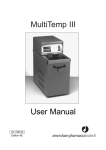
4.2 Needle and tubing
The A–900 has separate needles for puncturing and sampling; the air
needle, which punctures the septum of the vial and provides the
headspace pressure in the vial, and the sample needle for
transporting the sample from the vial into the loop of the valve.
The sample needle enters a vial as follows:
1
2
3
A
B
C
A: Initial position.
B: First the air/prepuncturing needle (2, Figure A) is lowered by
moving the complete needle arm downwards. The vial sensor
strip (3, Figure A) detects if there is a vial and at the same time
measures the vial height. If no vial is detected, the needle arm is
moved upwards and the A–900 will stop. When the A–900
detects a vial, the lowering speed of the arm is decreased to
provide just enough force to puncture the septum of the vial.
After forcing the air/prepuncturing needle into the vial, air is
applied to the vial. An air outlet nut reduces the pressure in the
vial to approximately 0.5 bar. The pressure in the vial is a
function of the diameter of the air outlet nut, the air needle and
the sample needle.
C: Finally the sample needle (1, Figure A) is lowered into the vial to
the depth programmed in System Settings. Now the A–900 is
ready for the first injection from this vial.
14
Auto Sampler A-900
User Manual 18-1117-50 Edition AC
18-1117-50_AC.qxd
1998-10-30 12:20
Sida 15 (1,1)
Maintenance
4
4.3 Syringe, sample loop and buffer tubing combinations
Four sizes of syringes are available for the dispenser: 100, 250, 500
and 1000 µl.
The 250 µl syringe is the standard syringe. When combined with the
standard 500 µl buffer tubing and the standard 100 µl sample loop,
the following injection volume range is available for the various
injection modes:
•
•
•
Flushed loop:
100 µl
Partial loopfill: 1 - 50 µl
µl pick-up:
1 - 25 µl
The maximum injection volumes are calculated as follows:
•
•
•
Flushed loop:
injection volume =
loop volume
Partial loopfill: max. injection volume = 50% of loop volume
µl pick-up:
max. injection volume = (loop volume - 3 x
needle volume) / 2
(standard needle
volume is 15 µl)
Sample volume requirements:
Partial loopfill*:
injection volume + flush volume (using tapered or standard vial)
µl pick-up*:
injection volume
(using tapered or standard vial)
Flushed loop*:
loop volume <100 µl:
minimum 3 x loop volume + flush volume
loop volume 100-499 µl:
minimum 2 x loop volume + flush volume
loop volume 500-1000 µl:
minimum 1.5 x loop volume + flush volume
*The first injection from a vial requires additional sample volume. A tapered vial
needs 4 µl extra volume and a standard vial needs 300 µl. These volumes must be
added to the sample volumes given above.
Note that:
• Flushed loop gives maximum reproducibility, but not maximum
accuracy, wich depends on the loop used.
Minimum sample loss = 230 µl (2 x loop overfill + flush volume
for needle).
• Partial loopfill gives maximum accuracy and reproducibility better
than 0.5% RSD for injection volumes > 5 µl.
Minimum sample loss (flush volume) = 30 µl.
• 30 µl is the recommended minimum flush volume.
35 µl is the recommended flush volume with an air segment.
40 µl is the default value for flush volume .
• µl Pick-up offers zero sample loss and maximum accuracy (same as
partial loop fill), but slightly less reproducibility. RSD is better
than 1% for injection volumes > 5 µl.
Auto Sampler A-900
User Manual 18-1117-50 Edition AC
15
18-1117-50_AC.qxd
1998-10-30 12:20
Sida 16 (1,1)
4 Maintenance
• If, for some reason, an air segment is selected from the
InjectionulPickup instruction in Manual:Flowpath, 5 µl of air is
injected in the system together with the sample.
Injection volumes smaller than 5 µl
Partial loopfill
Install a 100 µl syringe to obtain maximum reproducibility and
accuracy. Preferably install a 20 µl sample loop to avoid loss of
accuracy due to expansion of the loop content when switching from
inject to load position prior to sample loading. This is especially
recommended when working with high pressures (15.0-25.0 MPa).
Note that the minimum sample loss in partial loopfill mode is 30 µl
(recommended minimum flush volume) for the injection. For zero
sample loss injections, use the µl-pick injection mode.
µl Pick-up
Install a 100 µl syringe for optimum accuracy and reproducibility.
Note: To guarantee quantitative injections,do not install a smaller
sample loop than 100 µl !
Injection volumes up to 200 µl
With the standard 250 µl syringe, standard needle with tubing (15
µl) and standard 500 µl buffer tubing, but with a 200 µl sample
loop, the maximum injection volumes are:
Flushed loop:
200 µl
Partial loopfill: 100 µl
µl pick-up:
77 µl
(sample loss remains 230 µl since
loops > 100 µl need 2 x loop volumes
plus 30 µl flushed volume)
CAUTION! Smaller volumes than 5 µl may be injected, but
reproducibility and accuracy may not be < 0.5% for partial loopfill
or < 1% for µl pick-up!
For volumes larger than 200 µl
Install the 2000 µl buffer tubing. Install the appropriate sample loop
size and the appropriate syringe: Syringe volume > 2 x injection
volume. Injection volumes larger than 500 µl are possible, but the
sample may contaminate the syringe. Program sufficient wash after
use!
BUFFER TUBING
Syringe
100 µl
250 µl
500 µl
1000 µl
16
Buffer tubing
500 µl buffer tubing
500 µl buffer tubing
2000 µl buffer tubing
2000 µl buffer tubing
Loop volume
5-20 µl
20-200 µl
200-500 µl
500-1000 µl
Auto Sampler A-900
User Manual 18-1117-50 Edition AC
18-1117-50_AC.qxd
1998-10-30 12:20
Sida 17 (1,1)
Maintenance
4
4.4 Replacing the sample needle
Rheodyne nut
and ferrule
Teflon sleeve
To replace the sample needle, proceed as
follows:
•
Use the AutosamplerControl:
NeedleFront command in
Manual:Flowpath to move the needle to
the front.
•
Loosen the needle connection nut (Male
nut M6) that fixes the sample needle.
Male nut M6
CAUTION! Do not loosen or otherwise
unscrew the Hex screw!
•
Loosen the Rheodyne Rheflex nut that
connects the tubing to the injection valve.
•
Remove the sample needle by pulling it
out of its fitting.
•
Put in the new needle assembly.
•
Connect the loose end of needle
connection tubing to port 4 of the
injection valve (use a ferrule made of
PEEK).
Needle holder
Hex screw
Peek sample
needle
Air outlet nut
Air/prepuncturing
needle
Vial sensor strip
CAUTION! Do not tighten excessively;
it may block the tubing!
•
Check the sample needle height. The
default value for the needle height is 2
mm.
•
To check the needle height, place a vial in
tray segment A1, position 1. Remove tray
segment A2. Do an injection and check
the needle height in the vial.
If a tapered vial is used, an alternative
way of checking the needle height can be
useful; Do a large injection until air is
injected, then check the sample level and
adjust the needle height.
Auto Sampler A-900
User Manual 18-1117-50 Edition AC
•
The needle height is adjusted in System:
Settings:Specials:Needlehght in
UNICORN.
•
Wash to clean the new needle by issuing
the AutosamplerControl: InitialWash
command in Manual:Flowpath.
17
18-1117-50_AC.qxd
1998-10-30 12:20
Sida 18 (1,1)
4 Maintenance
4.5 SYRINGE
The A–900 is factory equipped with a 250 µl syringe, but can also
be equipped with a 100 µl, 500 µl or 1000 µl syringe.
To install another syringe, proceed as follows:
Note: Do not disconnect the power supply of the A–900. It is needed
to move the syringe.
Note: After the syringe change, the syringe must be in HOME
position.
• Move the syringe to the end position by
issuing the AutosamplerControl: SyringeEnd
command in Manual:Flowpath.
• Unscrew the syringe from the syringe valve,
Make sure that the Luer connector in the valve
remains in place.
• Disconnect the plunger from the syringe drive.
• Fill the new syringe with wash solvent. Remove
most air bubbles from the syringe.
• Connect the plunger of the filled syringe to the
syringe drive and connect the syringe with the
Luer connector at the syringe valve.
• Screw the syringe firmly into the Luer connector.
• Remove the air from the syringe by issuing the
AutosamplerControl: SyringeHome command
in Manual:Flowpath The syringe will move to
its HOME position and dispense its contents to
the syringe waste.
• If some air remains in the syringe, issue the
AutosamplerControl: SyringeEnd command in
Manual:Flowpath again. The syringe is filled
with wash solvent.
• Issue the AutosamplerControl: SyringeHome
command in Manual:Flowpath to dispense the
wash solvent to waste. If there is still air in the
syringe, repeat the previous action and tap gently
on the syringe as the wash solvent is dispensed to
the syringe waste.
• Issue the AutosamplerControl: InitialWash
command in Manual:Flowpath to perform a
standard wash. All tubing connected to the
syringe valve will be refilled and flushed.
• The A–900 is now ready for use.
18
Auto Sampler A-900
User Manual 18-1117-50 Edition AC
18-1117-50_AC.qxd
1998-10-30 12:20
Sida 19 (1,1)
Troubleshooting
5
5 Trouble shooting
WARNING! Always disconnect the power supply before
attempting to replace any item on the instrument
CAUTION! Only spare parts approved or supplied by Amersham
Pharmacia Biotech may be used for maintaining and servicing the
instrument.
WARNING! The instrument must not be opened by the user. It
contains high voltage circuits that can deliver a lethal electric
shock.
5.1 Faults and actions
If the suggested actions do not correct the fault, call Amersham
Pharmacia Biotech.
Fault
Bad reproducibility
Injection valve switched dry
Syringe valve coupling leaking
Little or no peak
Peaks of different height
Air in the syringe
•
•
•
•
•
Replace rotor seal.
Check and tighten coupling. Replace if necessary.
Syringe leaking problem. Replace syringe.
Ferrule not tightened in injection valve. Tighten ferrule.
Check and tighten coupling. Remove the air by issuing the
AutosamplerControl:SyringeEnd and
AutosamplerControl:SyringeHome commands in
Manual:Flowpath. If there is still air in the syringe, remove it
according to section 4.5.
Injection valve switches
too slowly
•
Rotor seal worn. Replace rotor seal.
Syringe action failed, motor
generates noise
•
Syringe not tightened enough when replaced. Tighten
syringe.
Sample needle bent.
No injection performed
•
Septa type wrong, septa deformed or needle depth set too
low. Replace needle and readjust needle depth if necessary.
Error meassage during
initial wash
•
Syringe valve not properly switched. Check syringe
Auto Sampler A-900
User Manual 18-1117-50 Edition AC
Action
19
18-1117-50_AC.qxd
1998-10-30 12:20
Sida 20 (1,1)
5 Troubleshooting
installation. Refit if necessary.
Fault
Needle destroyed in injection
using µl vial segments
Action
•
Segments badly oriented, or septa bent down. Replace
needle.
Ghost peaks at high pressure
•
Bad capillary connections. Replace connectors if necessary.
A-900 does not
execute commands
•
Syringe in END position. Order the syringe to HOME
position using the AutosamplerControl: SyringeHome
command in Manual:Flowpath
No sample injected
•
Syringe in END position. Order the syringe to HOME
position using the AutosamplerControl: SyringeHome
command in Manual:Flowpath
All segments in vial tray are not of the same type. Change to
same type.
Wrong vial position programmed. Program correct position.
•
•
Ghost or unexpected peaks
20
•
Washing not performed properly, due to:
Run out of washing liquid.
Washing liquid flows back in washing position
beacause waste flask not located below A-900.
Auto Sampler A-900
User Manual 18-1117-50 Edition AC
18-1117-50_AC.qxd
1998-10-30 12:20
Sida 21 (1,1)
Reference information
A
Reference information
A
Description
A.1 General
A unique sequence of valve switching and syringe dispenser
controlled sample withdrawal enables the A-900 to inject sample
volumes in a range from a few microliters to 1 ml in a simple and
reproducible manner.
Three different methods for injection can be selected:
• Flushed loop:
The sample loop is completely (quantitatively)
filled with sample resulting in extremely good
reproducibility (better than 0.3%).
• Partial loopfill:
The sample loop is partially filled with sample
giving low sample loss and allowing
programmable injection volumes.
• µl pick-up:
After aspiration from the vial, the sample
volume is transported into the loop with
transport liquid (mobile phase) from another
vial resulting in no sample loss.
The A-900 uses a syringe to aspirate the sample from a vial into the
sample loop. To prevent contamination of the syringe the A-900 is
equipped with a buffer tubing between the syringe and the injection
valve.
The wash solvent removes the sample from the buffer tubing and
sample needle and also rinses both components.
Auto Sampler A-900
User Manual 18-1117-50 Edition AC
21
18-1117-50_AC.qxd
1998-10-30 12:20
Sida 22 (1,1)
A Reference information
A.2 Instrument
Cover in open position
Buffer tubing
High pressure valve
Tubing guide
Needle arm
Tray segment
Syringe waste
Syringe dispenser
Wash solvent
bottle
Wash position
22
Drain wash
position
Condensed water
and leakage drain
Auto Sampler A-900
User Manual 18-1117-50 Edition AC
18-1117-50_AC.qxd
1998-10-30 12:20
Sida 23 (1,1)
Reference information
A
COMMUNICATION
UniNet 1,
computer network
UniNet1
Ventilation holes
WARNING:
MAKE SURE THAT AIR CIRCULATION
WILL NOT BE IMPEDED
!
WARNING – RISK OF FIRE
REPLACE FUSE AS MARKED
AVERTISSEMENT – RISCUE DE FEU
REMPLACEZ FUSÉ COMME INDIQUÉ
!
WARNING – RISK OF ELECTRIC SHOCK
DISCONNECT POWER BEFORE SERVICING
AVERTISSEMENT – RISCUE DE CHOC ELECTRIQUE
COUPER L'ALIMENTATION AVANT LA MAINTENANCE
RATED
FUSE RATING
VOLTAGE UL/CSA
IEC 127
5A 250V TL T 5A 250V
115 V
25A 250V TL T 25A 250V
230 V
POWER
ON 1
OFF 0
Mains switch
230/115 V~
VA
PART NO
18-1176-41
56-3026-29
MANUFACTURED BY
FOR
Hz
140 VA
CODE NO
50/60 Hz
1
0
SERIAL NO
6112
Mains input
Spark Holland B.V.
The Netherlands
Pharmacia Biotec h AB
SWEDEN
110-120 V
V~
220-240 V
Auto Sampler A-900
User Manual 18-1117-50 Edition AC
Fuses and
voltage selector
23
18-1117-50_AC.qxd
1998-10-30 12:20
Sida 24 (1,1)
A Reference information
A.3 Flushed loop injections
The switching sequence for a flushed loop injection is schematically
shown in the following figures:
Pump
2
Syringe
3
1
INJECT
Column
zy,
{,
|zy
zyy,
{,
|zy
{y,
zz
||
{y,
zz
||
4
6
5
Sample
Needle
The Initial position: the injection valve is in the INJECT
position. The sample needle and air needle have entered
the vial. The head-space pressure, applied through the
outer air needle, ensures that no air or vapour bubbles are
formed during sample aspiration.
Pump
2
Syringe
3
1
INJECT
4
6
Column
5
The syringe dispenser aspirates the “flush volume” from
the sample vial to fill the sample lines with sample and
remove wash solvent.
Sample
Needle
Pump
2
Syringe
3
1
LOAD
4
6
Column
5
Sample
Needle
The injection valve switches to the LOAD position,
placing a “sharp” sample front at the inlet of the sample
loop.
Pump
2
Syringe
3
1
LOAD
4
5
6
Column
For flushed loop injections, the sample loop is
quantitatively filled by transporting two or more times the
loop volume through the loop, depending on the volume
of the loop.
Sample
Needle
24
Auto Sampler A-900
User Manual 18-1117-50 Edition AC
18-1117-50_AC.qxd
1998-10-30 12:20
Sida 25 (1,1)
zy
,,
yy
,
z
,,
y
z
|
{{
y
|
{
Reference information
A
Pump
2
Syringe
3
1
INJECT
4
6
Column
5
Needle
Sample
The injection valve switches to the
INJECT position. The sample loop
is now part of the ÄKTA mobile
phase flow path. Sample is
transported to the column.
If one injection is to be made from each vial, a wash routine has to
be performed after every injection.
Air segment
An air segment should be used to reduce the amount of flush
volume. This air segment is at the front of the flush volume. It will
not be injected and will therefore not influence the injection. The air
segment is selected when the injection method is selected in Manual:
Flowpath.
With a standard needle, the flush volumes must be: minimum 30 µl
for injections with an air segment and 35 µl for injections without. If
the samples are highly viscous, it may be necessary to program larger
flush volumes and reduce the syringe speed to optimize performance.
|||
|
{{{
Needle
Injection loop
Buffer tubing
A
Sample
Eluent
Flush
B
Sample
Eluent
Flush
Auto Sampler A-900
User Manual 18-1117-50 Edition AC
Air
25
18-1117-50_AC.qxd
1998-10-30 12:20
Sida 26 (1,1)
A Reference information
A.4 Partial loopfill injections
The switching sequence for a partial loopfill injection is
schematically shown in the following figures:
Pump
2
Syringe
3
1
INJECT
Column
6
zy,
zy
|zy
{,y,
y
z
|
,
{
{y,
zz
||
{y,
zz
||
4
5
Sample
Needle
The Initial position: the injection valve is in the INJECT
position. The sample needle and air needle have entered
the vial. The head-space pressure, applied through the
outer air needle, ensures that no air or vapour bubbles are
formed during sample aspiration.
Pump
2
Syringe
3
1
INJECT
4
Column
6
5
The syringe dispenser aspirates the “flush volume” from
the sample vial to fill the sample lines with sample and
remove wash solvent.
Sample
Needle
Pump
2
Syringe
3
1
LOAD
4
6
Column
5
The injection valve switches to the LOAD position,
placing a “sharp” sample front at the inlet of the sample
loop.
Sample
Needle
Pump
2
Syringe
3
4
5
6
Column
For partial loopfill injections, the sample loop is filled by
transporting the programmed injection volume into the
sample loop.
Sample
Needle
1
LOAD
26
Auto Sampler A-900
User Manual 18-1117-50 Edition AC
18-1117-50_AC.qxd
1998-10-30 12:20
Sida 27 (1,1)
y
,
z
|{
z{
y
,
|
yyzyy,
z,,
yy
|{
|
{{
Reference information
A
Pump
2
Syringe
3
1
INJECT
4
6
Column
5
Needle
Sample
The injection valve switches to the
INJECT position. The sample loop
is now part of the ÄKTA mobile
phase flow path. Sample is
transported to the column.
Air segment
An air segment should be used to reduce the amount of flush
volume. This air segment is at the front of the flush volume and will
not be injected. The air segment can be selected when the injection
method is selected in Manual: Flowpath.
Needle
Auto Sampler A-900
User Manual 18-1117-50 Edition AC
Injection loop
Buffer tubing
A
Sample
Eluent
Flush
B
Sample
Eluent
Flush
Air
27
18-1117-50_AC.qxd
1998-10-30 12:20
Sida 28 (1,1)
A Reference information
A.5 µl Pick-up injection
The switching sequence for a µl pick-up injection is schematically
shown in the following figures:
Pump
2
Syringe
1
INJECT
3
6
Column
zy,
zy{,y,
|zy
{,
|zy
z|
4
5
Sample
Transport liquid
Needle
The Initial poaition: the injection valve is in the INJECT
position. The sample needle has entered the vial of
transport liquid (mobile phase used to avoid disturbing
the chromatogram with an additional peak of the
transport solvent).
Pump
2
Syringe
1
INJECT
3
4
6
Column
5
The syringe dispenser aspirates transport liquid from the
transport vial to fill the sample line with transport liquid
and remove wash solvents.
Sample
Transport liquid
Needle
Pump
2
Syringe
1
LOAD
3
4
6
Column
5
The needle moves from the transport vial to the sample
vial. The injection valve iwitches to the LOAD position.
Sample
Transport liquid
Needle
Pump
2
Syringe
3
1
LOAD
4
5
6
Column
The programmed injection volume is aspirated from the
sample vial.
28
Transport liquid
Sample
Needle
Auto Sampler A-900
User Manual 18-1117-50 Edition AC
18-1117-50_AC.qxd
1998-10-30 12:20
Sida 29 (1,1)
,
|
{
z
y
,
z
y
|
{
yyy
,,
z
z,
Reference information
The sample needle moves back to
the transport vial. The sample is
quantitatively transported into the
loop with 30 µl of transport liquid
(mobile phase) from the transport
vial.
A
Pump
2
Syringe
3
1
LOAD
4
6
Column
5
The injection valve switches to the
INJECT position. The sample loop
is now part of the ÄKTA mobile
phase flow path. Sample is
transported to the column.
Sample
Transport liquid
Needle
Pump
2
Syringe
3
1
INJECT
4
6
Column
5
Sample
Transport liquid
Needle
Air segment
Normally an air segment shall not be programmed for µl Pick-up
injections, since it then is injected with the sample into the system.
{
y
,
Needle
A
Injection loop
Transport
Sample
Buffer tubing
Fluent
Transport
Note: For µl pick-up injections, there will be no air pressure (headspace pressure) on the sample vial. This avoids sample errors due to
air expansion during vial exchange from the sample vial to the
transport solvent vial.
Auto Sampler A-900
User Manual 18-1117-50 Edition AC
29
18-1117-50_AC.qxd
1998-10-30 12:20
Sida 30 (1,1)
B Reference information
B
Technical specifications
Sampling
Sample capacity
Standard tray:
96 vials of 1.5 ml (Std),
12 vials per segment
Micro vial tray:
160 vials of 0.5 ml,
20 vials per segment
Vial dimensions (cap included) Maximum vial height: 47 mm
Minimum vial height: 32 mm
Loop volume
5 - 1000 µl
Dispenser syringe
100 µl, 250 µl (standard),
500 µl or 1000 µl syringe
Vial detection
Missing vial detection by vial sensor
Headspace pressure
Built-in compressor
Switching time injection valve Electrically <100 msec
Piercing precision needle
± 0.6 mm
Wash solvent
250 ml internal wash solvent bottle
Wetted parts
PEEK, PTFE, glass, Tefzel, alumina
ceramic and inert polymer
Analytical performance
Reproducibility
Memory effect
30
RSD <= 0.3% for flushed loop
injections
RSD <= 0.5% for partial loopfill
injections, injection volumes >5 µl
(5 µl sample, 100µl sample
loop, ≤2.5 MPa;
10 µl sample, 20 µl sample
loop, ≤25 MPa)
RSD <= 1.0% for µl pick-up
injections, injection volumes >5 µl
< 0.1% with programmable needle
wash
Physical
Dimensions (W x D x H)
Weight
280 x 540 x 440 mm
22 kg
Electrical
Power supply voltage
100–240 VAC, 50–60 Hz
Auto Sampler A-900
User Manual 18-1117-50 Edition AC
18-1117-50_AC.qxd
1998-10-30 12:20
Sida 31 (1,1)
Reference information
Power requirement
Fuses
For 100–120 VAC
For 220–240 VAC
Communication
Serial communication port
Standards
EMC Standards
Safety Standards
Environment
Working condition
Sound pressure level
Installation category
Pollution degree
Auto Sampler A-900
User Manual 18-1117-50 Edition AC
B
250 VA
Two 5.0 AT-fuses
(slow, _” x _”, UL/CSA)
Two 2.5 AT-fuses
(slow, 5 x 20 mm, IEC 127)
UniNet-1
This product meets the requirement of the
EMC Directive 89/336/EEC through the
harmonized standards EN 50081-1
(emission) and EN 50082-1 (immunity)
Note: The declaration of conformity is valid
for the instrument when it is
• used in laboratory locations
• used in the same state as it was
delivered from Amersham Pharmacia
Biotech except for alterations described
in the user manual
• used as “stand alone” unit or
connected to other CE labelled
Amersham Pharmacia Biotech
instruments or other products as
recommended.
This product meets the requirement of the
Low Voltage Directive (LVD) 73/23/EEC
through the harmonized standard
EN 61010-1.
+4 to +40 °C
20–95% relative humidity
<70 dB (A)
Category II, according to IEC 1010
Degree 2, according to IEC 1010
31
18-1117-50_AC.qxd
1998-10-30 12:20
Sida 32 (1,1)
C Reference information
C
Accessories and consumables
Item
32
Quantity per pack Code no.
Accessories
Tray segment set 1.5 ml vial (O.D. 12 mm)
Tray segment set 0.5 ml vial (O.D. 7 mm)
1
1
18-1119-90
18-1120-48
Consumables
Rheflex ferrule
Rheflex nut
Flange tube fitting 1/8”
Flange tube fitting 1/16”
Plunger replacement tip 100 µl
Plunger replacement tip 500 µl
Plunger replacement tip 250 µl
PEEK sample needle
Buffer tubing 2000 µl
Buffer tubing 500 µl
Wash solvent bottle 250 ml
Syringe 100 µl
Syringe 250 µl
Syringe 500 µl
Syringe 1000 µl
Luer lock connection, female
PEEK loop 100 µl
PEEK rotor (for Rheodyne 9740 valve)
Syringe waste tubing
Syringe tubing
Wash vial
Union nut air
10
10
5
5
10
10
10
1
1
1
1
1
1
1
1
1
1
1
1
1
1
1
18-1119-91
18-1119-92
18-1119-93
18-1119-94
18-1119-96
18-1119-97
18-1119-98
18-1119-99
18-1120-31
18-1120-32
18-1120-33
18-1120-34
18-1120-35
18-1120-36
18-1120-37
18-1120-38
18-1120-40
18-1120-41
18-1120-44
18-1120-45
18-1120-46
18-1120-47
Auto Sampler A-900
User Manual 18-1117-50 Edition AC
18-1117-50_AC.qxd
1998-10-30 12:20
Sida 33 (1,1)
Reference information
Auto Sampler A-900
User Manual 18-1117-50 Edition AC
C
33
18-1117-50_AC.qxd
1998-10-30 12:20
Sida 34 (1,1)
November 1998
C Reference information
34
Auto Sampler A-900
User Manual 18-1117-50 Edition AC
18-1117-50_AC.qxd
1998-10-30 12:20
Sida 35 (1,1)
1998-10-30 12:20
TC information ab, Uppsala. Printed in Sweden by T.K. i Uppsala AB
18-1117-50_AC.qxd
Sida 36 (1,1)