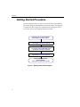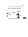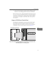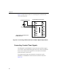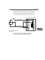
1
UM-17471-G DT9800 Series Getting Started Manual Seventh Edition March, 2002 Copyright © 1999, 2000, 2002 by Data Translation, Inc. All rights reserved. No part of this publication may be reproduced, stored in a retrieval system, or transmitted, in any form by any means, electronic, mechanical, by photocopying, recording, or otherwise, without the prior written permission of Data Translation, Inc. Information furnished by Data Translation, Inc. is believed to be accurate and reliable; however, no responsibility is assumed by Data Translation, Inc. for its use; nor for any infringements of patents or other rights of third parties which may result from its use. No license is granted by implication or otherwise under any patent rights of Data Translation, Inc. Use, duplication, or disclosure by the United States Government is subject to restrictions as set forth in subparagraph (c)(1)(ii) of the Rights in Technical Data and Computer software clause at 48 C.F.R, 252.227-7013, or in subparagraph (c)(2) of the Commercial computer Software Registered Rights clause at 48 C.F.R., 52-227-19 as applicable. Data Translation, Inc., 100 Locke Drive, Marlboro, MA 01752 Data Translation, Inc. 100 Locke Drive Marlboro, MA 01752-1192 (508) 481-3700 www.datatranslation.com Fax: (508) 481-8620 E-mail: [email protected] Data Translation® is a registered trademark of Data Translation, Inc. DT-Open LayersTM, DataAcq SDKTM , DataAcq OMNI CDTM, DT-LV LinkTM, DTx-EZTM , and DT VPITM are trademarks of Data Translation, Inc. All other brand and product names are trademarks or registered trademarks of their respective companies. Table of Contents About this Manual . . . . . . . . . . . . . . . . . . . . . . . . . . . . . . . . . vii Intended Audience. . . . . . . . . . . . . . . . . . . . . . . . . . . . . . . . . . . . . . vii How this Manual is Organized . . . . . . . . . . . . . . . . . . . . . . . . . . . vii Conventions Used in this Manual . . . . . . . . . . . . . . . . . . . . . . . . viii Related Information . . . . . . . . . . . . . . . . . . . . . . . . . . . . . . . . . . . . viii Where To Get Help. . . . . . . . . . . . . . . . . . . . . . . . . . . . . . . . . . . . . . . x Chapter 1: Overview . . . . . . . . . . . . . . . . . . . . . . . . . . . . . . . . 1 DT9800 Series Key Hardware Features. . . . . . . . . . . . . . . . . . . . . . 2 DT9800 Series Software . . . . . . . . . . . . . . . . . . . . . . . . . . . . . . . . . . . 5 Getting Started Procedure . . . . . . . . . . . . . . . . . . . . . . . . . . . . . . . . . 6 Chapter 2: Preparing to Use a Function Module . . . . . . . . . 7 Unpacking . . . . . . . . . . . . . . . . . . . . . . . . . . . . . . . . . . . . . . . . . . . . . . 9 Checking the System Requirements . . . . . . . . . . . . . . . . . . . . . . . 10 Installing the Software. . . . . . . . . . . . . . . . . . . . . . . . . . . . . . . . . . . 11 Installing the Software in Windows 98, Windows Me, Windows 2000, or Windows XP . . . . . . . . . 11 Installing the Software on the Macintosh . . . . . . . . . . . . . . . 13 Viewing the DT9800 Series Documentation Online . . . . . . . . . . 14 Chapter 3: Installing a Function Module . . . . . . . . . . . . . . . 15 Attaching the Module to the Computer . . . . . . . . . . . . . . . . . . . . 17 Connecting Directly to the Host Computer . . . . . . . . . . . . . 17 Connecting to a Self-Powered USB Hub . . . . . . . . . . . . . . . . 19 Attaching Backplanes/Panels to the DT9800-EC or DT9800-EC-I Series. . . . . . . . . . . . . . . . . . . . . . . . . . . . . . . . . . . . . 23 Attaching a 5B or 7B Series Backplane . . . . . . . . . . . . . . . . . . 25 Attaching an AC1324 Screw Terminal Panel. . . . . . . . . . . . . 26 iii Contents Attaching a PB16H Opto-22 Backplane . . . . . . . . . . . . . . . . . 27 Attaching an STP-EZ Screw Terminal Panel . . . . . . . . . . . . . 27 Chapter 4: Configuring the Module and/or Device Driver . 29 Configuring the DT9800 Series Device Driver . . . . . . . . . . . . . . . 31 Configuring the DT9800-EC andDT9800-EC-I Series Function Modules. . . . . . . . . . . . . . . . . . . . . . . . . . . . . . . . . . . . . . 33 Chapter 5: Wiring Signals . . . . . . . . . . . . . . . . . . . . . . . . . . . 35 Wiring Signals to the DT9800 Standard or DT9800-MAC Series 37 Connecting Analog Input Signals. . . . . . . . . . . . . . . . . . . . . . 40 Connecting Single-Ended Voltage Inputs . . . . . . . . . . . 41 Connecting Pseudo-Differential Voltage Inputs . . . . . . 42 Connecting Differential Voltage Inputs . . . . . . . . . . . . . 43 Connecting Current Loop Inputs . . . . . . . . . . . . . . . . . . 46 Connecting Thermocouple Inputs . . . . . . . . . . . . . . . . . 47 Connecting Analog Output Signals . . . . . . . . . . . . . . . . . . . . 49 Connecting Digital I/O Signals. . . . . . . . . . . . . . . . . . . . . . . . 49 Connecting Counter/Timer Signals . . . . . . . . . . . . . . . . . . . . 51 Connecting Event Counting Signals . . . . . . . . . . . . . . . 51 Connecting Frequency Measurement Signals . . . . . . . . 54 Connecting Pulse Output Signals . . . . . . . . . . . . . . . . . . 56 Wiring Signals to the DT9800-EC or DT9800-EC-I Series. . . . . . 59 Connecting Analog Input Signals. . . . . . . . . . . . . . . . . . . . . . 64 Using 5B or 7B Series Signal Conditioning Modules . . 64 Using an AC1324 Screw Terminal Panel . . . . . . . . . . . . 65 Connecting Single-Ended Voltage Inputs . . . . . . . . 68 Connecting Pseudo-Differential Voltage Inputs. . . 69 Connecting Differential Voltage Inputs . . . . . . . . . . 70 Connecting Current Loop Inputs . . . . . . . . . . . . . . . 73 Connecting Analog Output Signals . . . . . . . . . . . . . . . . . . . . 74 iv Contents Connecting Digital I/O Signals. . . . . . . . . . . . . . . . . . . . . . . . 76 Connecting Counter/Timer Signals . . . . . . . . . . . . . . . . . . . . 80 Connecting Event Counting Signals . . . . . . . . . . . . . . . 82 Connecting Frequency Measurement Signals . . . . . . . . 84 Connecting Pulse Output Signals . . . . . . . . . . . . . . . . . . 86 Chapter 6: Verifying the Operation of a Function Module . 89 Using Windows 98, Windows Me, Windows 2000, or Windows XP . . . . . . . . . . . . . . . . . . . . . . . . . . . . . . . . . . . . . . . . . . 91 Installing the Quick Data Acq Application . . . . . . . . . . . . . . 91 Running the Quick Data Acq Application . . . . . . . . . . . . . . 93 Performing a Single-Value Analog Input Operation . . 94 Performing a Single-Value Analog Output Operation 95 Performing a Continuous Analog Input Operation . . . 96 Performing a Single-Value Digital Input Operation . . 97 Performing a Single-Value Digital Output Operation . 98 Performing a Frequency Measurement Operation . . . 99 Performing a Pulse Output Operation . . . . . . . . . . . . . 100 Using the Macintosh . . . . . . . . . . . . . . . . . . . . . . . . . . . . . . . . . . . 102 Installing the Quick Data Acq Application . . . . . . . . . . . . . 102 Running the Quick Data Acq Application . . . . . . . . . . . . . 103 Performing a Single-Value Analog Input Operation . 104 Performing a Single-Value Analog Output Operation . . . . . . . . . . . . . . . . . . . . . . . . . . . . . . . . . . . . 105 Performing a Continuous Analog Input Operation . . 106 Performing a Single-Value Digital Input Operation . 108 Performing a Single-Value Digital Output Operation 108 Performing a Frequency Measurement Operation . . 109 Performing an Event Counting Operation . . . . . . . . . 110 Performing a Pulse Output Operation . . . . . . . . . . . . . 111 Index . . . . . . . . . . . . . . . . . . . . . . . . . . . . . . . . . . . . . . . . . . . . 113 v Contents vi About this Manual This manual describes how to install and set up your DT9800 Series function module and device driver, and verify that your module is working properly. Intended Audience This document is intended for engineers, scientists, technicians, or others responsible for installing and setting up DT9800 Series function modules to perform data acquisition operations. It is assumed that you are familiar with the requirements of your application. It is also assumed that you are familiar with the Microsoft Windows 98, Windows Me (Millennium Edition), Windows 2000, Windows XP, or the Macintosh operating system. How this Manual is Organized This manual is organized as follows: • Chapter 1, “Overview,” describes the key features of the DT9800 Series hardware and the DT9800 Series software, and provides an overview of the DT9800 Series getting started procedure. • Chapter 2, “Preparing to Use a Function Module,” describes how to unpack the DT9800 Series package, check the system requirements, install the DT9800 Series software using Windows 98, Windows Me, Windows 2000, Windows XP, or MAC OS 9.0, and view the DT9800 Series documentation online. • Chapter 3, “Installing a Function Module,” describes how to install the DT9800 Series function module. • Chapter 4, “Configuring the Module and/or Device Driver,” describes how to configure the device driver and the function module. vii About this Manual • Chapter 5, “Wiring Signals,” describes how to wire signals to a DT9800 Series function module. • Chapter 6, “Verifying the Operation of a Function Module,” describes how to verify the operation of the function module with the Quick Data Acq application. An index completes this manual. Conventions Used in this Manual The following conventions are used in this manual: • Notes provide useful information that requires special emphasis, cautions provide information to help you avoid losing data or damaging your equipment, and warnings provide information to help you avoid catastrophic damage to yourself or your equipment. • Items that you select or type are shown in bold. • Courier font is used to represent source code. Related Information Refer to the following documents for more information on using the DT9800 Series module: • Benefits of the Universal Serial Bus for Data Acquisition. This white paper describes why USB is an attractive alternative for data acquisition. It is available on the Data Translation® web site (www.datatranslation.com). • DT9800 Series User’s Manual (UM-17473), included on the Data Acqusition OMNI CDTM provided with the DT9800 Series function module. This manual describes the features of the DT9800 Series function modules and the DT9800 Series Device Driver in detail. viii About this Manual • DT Measure Foundry Getting Started Manual (UM-19298) and online help. These documents describe how to use DT Measure Foundry™ to build drag-and-drop test and measurement applications for Data Translation® data acquisition devices without programming. • DataAcq SDK User’s Manual (UM-18326). For programmers who are developing their own application programs using the Microsoft C compiler, this manual describes how to use the DT-Open LayersTM DataAcq SDKTM in Windows 98, Windows Me, Windows 2000, or Windows XP to access the capabilities of Data Translation data acquisition devices. This manual is included on the Data Acquisition OMNI CD. • DTx-EZ Getting Started Manual (UM-15428). This manual describes how to use the ActiveX controls provided in DTx-EZTM to access the capabilities of Data Translation data acquisition devices in Microsoft Visual Basic® or Visual C++®. • DT VPI User Manual (UM-16150). This manual describes how to use DT VPITM and the Agilent® VEETM visual programming language to access the capabilities of Data Translation data acquisition devices. • DT-LV Link Getting Started Manual (UM-15790). This manual describes how to use DT-LV LinkTM with the LabVIEW® graphical programming language to access the capabilities of Data Translation data acquisition devices. • Microsoft Windows 98, Windows Me, Windows 2000, Windows XP, or Macintosh documentation. • USB web site (http://www.usb.org). ix About this Manual Where To Get Help Should you run into problems installing or using a DT9800 Series function module, our Technical Support Department is available to provide technical assistance. Refer to the DT9800 Series User’s Manual for information on how to contact the Technical Support Department (refer to page 14 for information on viewing this manual). If you are outside the U.S. or Canada, call your local distributor, whose number is listed in your Data Translation product handbook. x 1 Overview DT9800 Series Key Hardware Features. . . . . . . . . . . . . . . . . . . . . . 2 DT9800 Series Software . . . . . . . . . . . . . . . . . . . . . . . . . . . . . . . . . . . 5 Getting Started Procedure . . . . . . . . . . . . . . . . . . . . . . . . . . . . . . . . . 6 1 Chapter 1 DT9800 Series Key Hardware Features The DT9800 Series includes the following subseries: DT9800 Standard, DT9800-MAC, DT9800-EC, and DT9800-EC-I Series. The DT9800-EC Series modules are not isolated; the DT9800 Standard Series, DT9800-MAC Series, and DT9800-EC-I Series modules are isolated. In addition, the DT9800-EC and DT9800-EC-I Series modules support the use of optional backplanes and screw terminal panels that provide signal conditioning and other features, and the DT9805 and DT9806 support thermocouple inputs. Table 1 lists the function modules in each series and the key features of each module. Table 1: Key Features Among the DT9800 Series Series DT9800 Standard Series 2 # of Analog Inputs Analog Input Sample Rate # of Analog Outputs # of Digital I/O Lines # of Counter /Timers Operating System Function Modules Windows DT9801a 16 SE/ 8 DI 100 kS/s 0 8 input, 8 output 2 DT9802a 16 SE/ 8 DI 100 kS/s 2 8 input, 8 output 2 DT9803b 16 SE/ 8 DI 100 kS/s 0 8 input, 8 output 2 DT9804b 16 SE/ 8 DI 100 kS/s 2 8 input, 8 output 2 DT9805c 16 SE/ 8 DI/ 7 thermocouples and 1 CJC 50 kS/s 0 8 input, 8 output 2 Overview Table 1: Key Features Among the DT9800 Series (cont.) # of Analog Outputs 16 SE/ 8 DI/ 7 thermocouples and 1 CJC 50 kS/s 2 DT9801MACa 16 SE/ 8 DI 100 kS/s 0 8 input, 8 output 2 DT9802MACa 16 SE/ 8 DI 100 kS/s 2 8 input, 8 output 2 DT9803MACb 16 SE/ 8 DI 100 kS/s 0 8 input, 8 output 2 DT9804MACb 16 SE/ 8 DI 100 kS/s 2 8 input, 8 output 2 DT9801ECa 16 SE/ 8 DI 100 kS/s 0 8 input, 8 output 2 DT9802ECa 16 SE/ 8 DI 100 kS/s 2 8 input, 8 output 2 DT9803ECb 16 SE/ 8 DI 100 kS/s 0 8 input, 8 output 2 DT9804ECb 16 SE/ 8 DI 100 kS/s 2 8 input, 8 output 2 Operating System Function Modules DT9800 Standard Series (cont.) Windows DT9806c DT9800MAC Series Macintosh Series DT9800EC Seriesd Windows # of Digital I/O Lines 1 Analog Input Sample Rate # of Analog Inputs 8 input, 8 output # of Counter /Timers 2 1 1 1 1 1 1 1 1 3 Chapter 1 Table 1: Key Features Among the DT9800 Series (cont.) Series DT9800EC-I Series Analog Input Sample Rate # of Analog Outputs # of Digital I/O Lines Operating System Function Modules # of Analog Inputs # of Counter /Timers Windows DT9801EC-Ia 16 SE/ 8 DI 100 kS/s 0 8 input, 8 output 2 DT9802EC-Ia 16 SE/ 8 DI 100 kS/s 2 8 input, 8 output 2 DT9803EC-Ib 16 SE/ 8 DI 100 kS/s 0 8 input, 8 output 2 DT9804EC-Ib 16 SE/ 8 DI 100 kS/s 2 8 input, 8 output 2 a. The resolution is 12 bits. b. The resolution is 16 bits. c. Supported analog input gains on the DT9805 and DT9806 are 1, 10, 100, and 500; all other modules provide analog input gains of 1, 2, 4, and 8. d. The DT9800-EC Series modules are not isolated; the DT9800-EC-I Series modules and all other modules are isolated. 4 Overview DT9800 Series Software The DT9800 Series software, which is shipped on the Data Acquisition OMNI CD, includes the following software components: 1 • DT9800 Series Device Driver − This software must be installed and loaded before you can use a DT9800 Series module with any of the supported software packages or utilities. 1 • The Quick Data Acq application − This application provides a quick way to get a DT9800 Series module up and running. Using the Quick Data Acq application, you can verify the features of the module, display data on the screen, and save data to disk. 1 • Calibration Utility − This software allows you to calibrate the analog I/O circuitry of the module. Note that this software is not provided for the Macintosh at this time. Refer to the DT9800 Series User’s Manual for information on using this utility. • DT9800 Series User’s Manual (in PDF format) − This describes the features of the DT9800 Series modules and how to use the DT9800 Series Device Driver with DT-Open Layers-compliant software to write an application program. • This manual (in PDF format). • Rev 4.0 of Adobe Acrobat Reader − Allows you to view and print the PDF files. 1 1 1 1 1 1 5 Chapter 1 Getting Started Procedure The flow diagram shown in Figure 1 illustrates the steps needed to get started using the DT9800 Series function modules. This diagram is repeated in each chapter; the shaded area in the diagram shows you where you are in the getting started procedure. Preparing to Use a Function Module (see Chapter 2 starting on page 7) Install the Function Module (see Chapter 3 starting on page 15) Configure the Module and/or Device Driver (not required for the DT9800-MAC Series; see Chapter 4 starting on page 29) Wire Signals (see Chapter 5 starting on page 35) Verify the Operation of the Function Module (see Chapter 6 starting on page 89) Figure 1: Getting Started Flow Diagram 6 2 Preparing to Use a Function Module Unpacking . . . . . . . . . . . . . . . . . . . . . . . . . . . . . . . . . . . . . . . . . . . . . . 9 Checking the System Requirements . . . . . . . . . . . . . . . . . . . . . . . 10 Installing the Software. . . . . . . . . . . . . . . . . . . . . . . . . . . . . . . . . . . 11 Viewing the DT9800 Series Documentation Online . . . . . . . . . . 14 7 Chapter 2 Prepare to Use a Function Module (this chapter) Install the Function Module (see Chapter 3 starting on page 15) Configure the Module and/or Device Driver (not required for the DT9800-MAC Series; see Chapter 4 starting on page 29) Wire Signals (see Chapter 5 starting on page 35) Verify the Operation of the Function Module (see Chapter 6 starting on page 89) 8 Preparing to Use a Function Module Unpacking Open the shipping box and verify that the following items are present: • DT9800 Series function module, • EP310 USB cable, • Color labels for the screw terminal blocks (for DT9800 Standard and DT9800-MAC Series modules only), and • For the Macintosh, the DT9800 Series Software and Documentation CD-ROM; for Windows 98, Windows Me, Windows 2000, or Windows XP, the Data Acquisition OMNI CD. If an item is missing or damaged, contact Data Translation. If you are in the United States, call the Customer Service Department at (508) 481-3700. An application engineer will guide you through the appropriate steps for replacing missing or damaged items. If you are located outside the United States, call your local distributor, listed in your Data Translation Product Handbook. Once you have unpacked your function module, check the system requirements, as described in the next section. 2 2 2 2 2 2 2 2 2 9 Chapter 2 Checking the System Requirements For reliable operation, your DT9800 Standard Series function modules require the items listed in Table 2. Table 2: Minimum System Requirements Function Module DT9800 Standard Series, DT9800-EC Series, and DT9800-EC-I Series DT9800-MAC Series Feature Minimum Requirements Operating System Windows 98, Windows Me, Windows 2000, or Windows XP Processor 80486, Pentium, or compatible USB Ports One or more RAM 16 MB or more CD-ROM Drives One or more Monitor VGA, or compatible, display (640 x 480 or higher, 256 colors recommended) Operating System MAC OS 9.0 Processor iMac, iBook, or Power Mac G4 USB Ports One or more RAM 32 MB or more CD-ROM Drives One or more Monitor VGA, or compatible, display (640 x 480 or higher, 256 colors recommended) Once you have verified that your system meets the system requirements, install the software as described in the next section. 10 Preparing to Use a Function Module Installing the Software If you are using Windows 98, Windows Me, Windows 2000, or Windows XP continue with the instructions in the next section. If you are using the Macintosh, continue with the instructions on page 13. 2 2 Installing the Software in Windows 98, Windows Me, Windows 2000, or Windows XP 2 CAUTION: This version of the software provides WDM-compliant device drivers and DLLs (version 5.0 or greater). Other Data Translation boards may not provide WDM-compliant files. You cannot use a DT9800 Series board at the same time as another Data Translation board unless both devices provide WDM-compliant files. To install the software, perform the following steps: 1. Insert the Data Acquisition OMNI CD into your CD-ROM drive. 2. Click Start from the Task Bar, then click Run. The Run dialog box appears. 3. In the Command Line edit box, enter D:\LAUNCH.EXE. If your CD-ROM is not in drive D:, enter the letter of the drive where your CD-ROM is located. 4. Click OK. The Data Acquisition Software setup program starts. 5. Click Install Products. A list of software products that you can install appears. 6. Click Device Drivers. The DT-Open Layers Data Acquisition software wizard appears. 2 2 2 2 2 2 11 Chapter 2 7. Click Next. You are prompted for the destination location. 8. Either change the directory path and/or name using Browse or accept the default directory, then click Next. You are prompted to select the software components to install. 9. Select DT9800 Series, then click Next. You are prompted for the program folder name. 10. Either change the program folder name or accept the default program folder name, then click Next. The files are copied to the destination directory. 11. Click Finish. The DT Data Acquisition Software setup program reappears. 12. Click Main Menu. 13. Click Exit. 12 Preparing to Use a Function Module Installing the Software on the Macintosh You can install the software on the Macintosh in one of the following ways: • If you have an Internet connection and OS 9, you can download the latest software (including drivers and the Quick Data Acq application) from the Data Translation web site. For more information, refer to “Connecting Directly to the Host Computer” on page 17 or “Connecting to a Self-Powered USB Hub” on page 19. 2 2 2 • If you want to install the software on the supplied CD-ROM, perform the following steps: 1. Insert the DT9800 Series CD-ROM into your CD-ROM drive. 2. Drag the contents of the DT9800 Drivers folder from the CD-ROM to the System folder on your hard disk. This folder contains the USB DT9800 Data Acq Driver and USB DT9800 Data Acq Loader files. 3. 2 2 Click OK to place the files in the Extensions folder. 2 2 2 2 13 Chapter 2 Viewing the DT9800 Series Documentation Online Once you have installed the DT9800 Series software, you can view the DT9800 Series documentation by clicking the manual title. For Windows 98, Windows Me, Windows 2000, and Windows XP, you can access the manuals from the Data Translation, Inc\DT9800 Series program group. For the Macintosh, you can access the manuals from the Quick Data Acq folder. To view the documentation, you need Adobe Acrobat Reader, version 4.0. For Windows 98, Windows Me, Windows 2000, and Windows XP, Adobe Acrobat Reader is included on the CD-ROM. For the Macintosh, you can download Adobe Acrobat Reader from the Adobe web site at www.adobe.com. Here are a few helpful hints about using Adobe Acrobat Reader: • To navigate to a specific section of the document, click a heading from the table of contents on the left side of the document. • Within the document, click the text shown in blue to jump to the appropriate reference (the pointer changes from a hand to an index finger). • To go back to the page from which the jump was made, click the right mouse button and Go Back, or from the main menu, click Document, then Go Back. • To print the document, from the main menu, click File, then Print. • To increase or decrease the size of the displayed document, from the main menu, click View, then Zoom. • By default, text and monochrome images are smoothed in Acrobat Reader, resulting in blurry images. If you wish, you can turn smoothing off by clicking File, then Preferences/General, and unchecking Smooth Text and Images. 14 3 Installing a Function Module Attaching the Module to the Computer . . . . . . . . . . . . . . . . . . . . 17 Attaching Backplanes/Panels to the DT9800-EC or DT9800-EC-I Series. . . . . . . . . . . . . . . . . . . . . . . . . . . . . . . . . . . . . 23 15 Chapter 3 Prepare to Use a Function Module (see Chapter 2 starting on page 7) Install the Function Module (this chapter) Configure the Device Driver and/or Module (see Chapter 4 starting on page 29) Wire Signals to the Module (see Chapter 5 starting on page 35) Verify the Operation of the Function Module (see Chapter 6 starting on page 89) Note: All DT9800 Series modules are factory-calibrated and require no further adjustment prior to installation. If you are using the DT9800 Standard, DT9800-EC, or DT9800-EC-I Series modules and decide later to recalibrate them, refer to the DT9800 Series User’s Manual for instructions (see page 14 for information on viewing this manual). DT9800-MAC Series modules currently do not support software calibration. 16 Installing a Function Module Attaching the Module to the Computer You can attach a DT9800 Series module to the host computer in one of two ways: 3 • Connect directly to a USB port of the host computer, described on this page. Use this method if one or two DT9800 Series function modules are sufficient for your application. 3 • Connect to one or more self-powered USB hubs, described on page 19. Use this method if your application requires more than two DT9800 Series function modules connected to the host computer. 3 Note: DT9800 Series modules are low-power devices (using less than 500 mA); therefore, they do not require external power supplies. 3 3 Connecting Directly to the Host Computer Generally, host computers have two USB ports. These ports are completely independent. To connect a DT9800 Series function module directly to a USB port of the computer, perform the following steps: 1. Attach one end of the EP310 cable, which is shipped with the DT9800 Series function module, to the USB port on the module. 2. Attach the other end of the EP310 cable to one of the USB ports on the host computer, as shown in Figure 2. The operating system automatically detects the USB device. 3 3 3 3 17 Chapter 3 USB Ports DT9800 Series Function Modules Host Computer EP310 Cables Figure 2: Attaching the DT9800 Series Function Module Directly to the Host Computer 3. If you previously installed the DT9800 Series Device Driver, ignore the remaining steps, and repeat steps 1 and 2 to attach another DT9800 Series function module to the host computer, if desired. If you are using Windows 98, Windows Me, Windows 2000, or Windows XP, and you have not yet installed the DT9800 Series Device Driver, the New Hardware Found wizard appears. Click Next to have the wizard search for the DT9800 Series Device Driver, then proceed to step 4. If you are using the Macintosh, you did not install the software from the CD-ROM, and you have an Internet connection and OS 9, you are prompted to install the latest software from the Data Translation web site. Follow the instructions on the screen for automatic software update. This allows you to download and install the DT9800 Series drivers, and optionally, the Quick Data Acq software and required files. Then, proceed to step 8. 18 4. Click the option to search for the driver, then click Next. 5. Click the option to specify the location, then enter x:\Products\Core\DT9800 as the path from which to copy files (where x is the letter of your CD-ROM drive), then click Next. 6. Click Next. Installing a Function Module 7. 8. Click Finish. A New Hardware Found dialog box appears indicating that Windows is installing the driver for the USB device. Repeat the steps 1 to 2 to attach another DT9800 Series function module to the host computer, if desired. Note: You can unplug a module, then plug it in again, if you wish, without causing damage. This process is called hot-swapping. Your application may take a few seconds to recognize a module once it is plugged back in. 3 3 3 3 Connecting to a Self-Powered USB Hub Self-powered USB hubs are USB hubs that are powered by their own external power supply. Theoretically, you can connect up to five self-powered USB hubs to a USB port on the host computer. However, the practical number of DT9800 Series function modules that you can connect to a single USB port depends on the throughput you want to achieve. Each of the hubs supports up to four DT9800 Series function modules. Note: The bandwidth of the USB bus is 12 Mbits/second. Each DT9800 Series function module running at full speed (100 kHz) requires 200 kB of this bandwidth. Therefore, if you want to achieve full throughput on each function module, you should connect no more than four DT9800 Series function modules to a single USB port. 3 3 3 3 3 19 Chapter 3 To connect a DT9800 Series function module to a self-powered USB hub, perform the following steps: 1. Attach one end of the EP310 cable to the DT9800 Series module and the other end of the EP310 cable to a self-powered USB hub. 2. Connect the power supply for the self-powered USB hub to an external power supply. 3. Connect the hub to the USB port on the host computer using another EP310 cable. The operating system automatically detects the USB device. 4. If you are using Windows 98, Windows Me, Windows 2000, Windows XP, or the Macintosh and previously installed the DT9800 Series Device Driver, ignore the remaining steps, and repeat steps 1 to 3 until you have attached the number of hubs (up to five) and function modules (up to four per hub) that you desire. If you are using Windows 98, Windows Me, Windows 2000, or Windows XP, and you have not installed the DT9800 Series Device Driver, the New Hardware Found wizard appears. Click Next to have the wizard search for the DT9800 Series Device Driver. Proceed to step 5. If you are using the Macintosh, you did not install the software from the CD-ROM, and you have an internet connection and OS 9, you are prompted to install the latest software from the Data Translation web site. Follow the instructions on the screen for automatic software update. This allows you to download and install the DT9800 Series drivers, and optionally, the Quick Data Acq software and required files. Then, proceed to step 10. 20 5. Click the option to search for the driver, then click Next. 6. Click the option to specify the location, then enter x:\Products\Core\DT9820 as the path from which to copy files (where x is the letter of your CD-ROM drive), then click Next. 7. Click Next. Installing a Function Module 8. 9. Click Finish. A New Hardware Found dialog box appears indicating that Windows is installing the driver for the USB device. Repeat steps 1 to 3 until you have attached the number of hubs (up to five) and function modules (up to four per hub) that you desire. Refer to Figure 3. The operating system automatically detects the USB devices as they are installed. 3 3 3 DT9800 Series Function Module EP310 Cables DT9800 Series Function Module 3 Host Computer EP310 Cable EP310 Cable 3 Self-Powered USB Hubs Power Supply for Hub 3 DT9800 Series Function Module DT9800 Series Function Module EP310 Cables Figure 3: Attaching DT9800 Series Function Modules to the Host Computer Using Self-Powered USB Hubs Note: You can unplug a module, then plug it in again, if you wish, without causing damage. This process is called hot-swapping. 3 3 3 21 Chapter 3 Your application may take a few seconds to recognize a module once it is plugged back in. If you are using a DT9800-EC or DT9800-EC-I Series module, continue with the next section. Otherwise, continue with the instructions on wiring in Chapter 4 starting on page 29. 22 Installing a Function Module Attaching Backplanes/Panels to the DT9800-EC or DT9800-EC-I Series Only the DT9800-EC and DT9800-EC-I Series function modules support Analog Devices 5B and 7B Series backplanes, the Opto-22 PB16H digital I/O backplane, and the Data Translation STP-EZ backplane and AC1324 screw terminal panel. The DT9800-EC and DT9800-EC-I Series function modules provide the following three connectors: • Connector J6 − Supports 5B and 7B Series backplanes or an AC1324 screw terminal panel for analog input connections. Specific 5B and 7B Series backplanes that are supported include the following: − 5B01 − a 16-channel backplane for 5B Series signal conditioning modules, − 5B08 − an 8-channel backplane for 5B Series signal conditioning modules, − 7BP16-1 − a 16-channel backplane for 7B Series signal conditioning modules, − 7BP08-1 − an 8-channel backplane for 7B Series signal conditioning modules, and − 7BP04-1 − a 4-channel backplane for 7B Series signal conditioning modules. • Connector J5 − Supports an AC1324 screw terminal panel for analog output, dynamic digital output, counter/timer, and power connections. • Connector J4 − Supports the STP-EZ and the PB16H digital I/O backplane. The PB16H supports eight digital inputs at locations 0 to 7, and eight digital outputs at locations 8 to 15. 3 3 3 3 3 3 3 3 3 23 Chapter 3 Figure 4 shows the location of these connectors on the DT9800-EC and DT9800-EC-I Series function modules. DT9800-EC or DT9800-EC-I Series Function Module J5 J6 J4 Figure 4: J6, J5, and J4 Connectors This section describes how to connect a 5B or 7B Series backplane, a AC1324 screw terminal panel, and/or a PB16H Opto-22 backplane to your DT9800-EC or DT9800-EC-I Series function module. 24 Installing a Function Module Attaching a 5B or 7B Series Backplane To connect a 5B01, 5B08, 7BP16-1, 7BP08-1, or 7BP04-1 signal conditioning backplane to a DT9800-EC or DT9800-EC-I Series function module, perform the following steps: 1. Plug one end of an AC1315 cable into the J6 connector of the DT9800-EC or DT9800-EC-I Series function module, as shown in Figure 5. 3 3 3 J6 Connector DT9800-EC/ DT9800-EC-I AC1315 Cable To Host Computer 3 Figure 5: Connecting the AC1315 Cable to the DT9800-EC or DT9800-EC-I Series Function Module 2. 3 If you are using a 5B Series backplane, plug the other end of the AC1315 cable into the 26-pin connector on the 5B Series backplane, as shown in Figure 6. 3 3 J6 Connector DT9800-EC/ DT9800-EC-I 5B Series Backplane AC1315 Cable Figure 6: Connecting the AC1315 Cable to the 5B Series Backplane To Host Computer 3 3 25 Chapter 3 If you are using a 7B Series backplane, plug the other end of the AC1315 cable into the 26-pin connector of the AC1393 adapter cable; then, attach the 25-pin connector of the AC1393 adapter cable to the 7B Series backplane, as shown in Figure 7. AC1393 Adapter Cable J6 Connector DT9800-EC/ DT9800-EC-I 7B Series Backplane To Host Computer AC1315 Cable Figure 7: Connecting the AC1315 Cable to the AC1393 Adapter Cable and to the 7B Series Backplane Attaching an AC1324 Screw Terminal Panel To connect an AC1324 screw terminal panel to a DT9800-EC or DT9800-EC-I Series function module, perform the following steps: 1. Plug one end of an AC1315 cable into the J6 or J5 connector of the DT9800-EC or DT9800-EC-I Series function module. 2. Plug the other end of the AC1315 cable into the 26-pin connector on the AC1324 screw terminal panel, as shown in Figure 8. J6 or J5 Connector DT9800-EC/ DT9800-EC-I AC1324 To Host Computer AC1315 Cable Figure 8: Connecting the AC1324 Screw Terminal Panel to the DT9800-EC or DT9800-EC-I Series Function Module 26 Installing a Function Module Attaching a PB16H Opto-22 Backplane To connect a PB16H Opto-22 backplane to a DT9800-EC or DT9800-EC-I Series function module, perform the following steps: 1. Plug one end of an EP035 cable into the J4 connector of the DT9800-EC or DT9800-EC-I Series function module. 2. Plug the other end of the EP035 cable into the 50-pin connector on the PB16H Opto-22 backplane, as shown in Figure 9. 3 3 3 J4 Connector DT9800-EC/ DT9800-EC-I PB16H Opto-22 Backplane EP035 50-Pin Ribbon Cable To Host Computer Figure 9: Connecting the PB16H Opto-22 Backplane to the DT9800-EC or DT9800-EC-I Series Function Module 3 3 3 Attaching an STP-EZ Screw Terminal Panel To connect an STP-EZ screw terminal panel to a DT9800-EC or DT9800-EC-I Series function module, perform the following steps: 1. 2. Attach one end of the 50-pin cable that is shipped with the STP-EZ screw terminal panel into connector J4 on the DT9800-EC or DT9800-EC-I board. 3 3 Attach the other end of the cable to the J1 connector on the STP-EZ screw terminal panel, as shown in Figure 10. 3 27 Chapter 3 J4 Connector DT9800-EC/ DT9800-EC-I STP-EZ J1 Connector 50-Pin Ribbon Cable To Host Computer Figure 10: Connecting the STP-EZ to the DT9800-EC or DT9800-EC-I Function Module 28 4 Configuring the Module and/or Device Driver Configuring the DT9800 Series Device Driver . . . . . . . . . . . . . . . 31 Configuring the DT9800-EC andDT9800-EC-I Series Function Modules. . . . . . . . . . . . . . . . . . . . . . . . . . . . . . . . . . . . . . 33 29 Chapter 4 Prepare to Use a Function Module (see Chapter 2 starting on page 7) Install the Function Module (see Chapter 3 starting on page 15) Configure the Module and/or Device Driver (not required for the DT9800-MAC Series; this chapter) Wire Signals (see Chapter 5 starting on page 35) Verify the Operation of the Function Module (see Chapter 6 starting on page 89) If you are using a DT9800 Standard Series, DT9800-EC Series, or DT9800-EC-I Series module, you must configure the device driver; refer to page 31 for information. In addition, if you are using a DT9800-EC or DT9800EC-I Series module, you must configure the module; refer to page 33 for information. If you are using a DT9800-MAC function module, it is not necessary to configure the DT9800 Series Device Driver or function module. Therefore, skip this chapter and continue with the instructions for wiring signals in Chapter 5 starting on page 35. 30 Configuring the Module and/or Device Driver Configuring the DT9800 Series Device Driver This section describes how to configure the device driver for a DT9800 Standard Series, DT9800-EC Series, or DT9800-EC-I Series function module to use or not use bias-return termination resistance. 4 4 To configure the device driver, perform the following steps: 1. If you have not already done so, power up the host computer and all peripherals. 2. From the Control Panel, double-click the Open Layers Data Acquisition Control Panel icon. The Open Layers dialog box appears. 3. Click the DT9800 Series function module that you want to configure, then click Advanced. The DT9800 Configuration dialog box appears. 4. If you are using differential analog input channels, it is recommended that you select the 10k Ohm Resistor Terminations checkbox for each analog input channel on the module. This ensures that 10 kΩ of bias return termination resistance is used for the analog input channels. (This is the default configuration.) Bias return termination resistance is particularly useful when your differential source is floating. If you are using single-ended analog input channels, clear the checkbox for each analog input channel so that bias return resistance is not used. 5. To continuously power the analog and/or digital outputs, select the Power Always On checkbox. The DT9800 Series module will remain on even when you exit from the applications that use the module. If you want to shut down power to the module, you must uncheck this checkbox and close the control panel. Once all 4 4 4 4 4 4 4 31 Chapter 4 applications that use this module are exited, the module will power down. The module will remain off until you either run an application that uses the module or click the Advanced button from the Open Layers Data Acquisition Control Panel. 6. Click OK. 7. If you want to rename the function module, click Edit Name; otherwise, go to step 9. 8. Enter a new name for the function module, then click OK. Note: This name is used to identify the module in all subsequent applications. 9. When you are finished configuring the function module, click Close. 10. Repeat steps 3 to 9 for the other function modules that you want to configure. 11. Close the Control Panel. If you are using a DT9800-EC or DT9800-EC-I function module, continue with the next section. Otherwise, continue with the instructions on wiring in Chapter 5 starting on page 35. 32 Configuring the Module and/or Device Driver Configuring the DT9800-EC and DT9800-EC-I Series Function Modules 4 This section describes how to configure a DT9800-EC or DT9800-EC-I function module for use with analog output modules on the 5B01 and 7BP16-1 signal conditioning backplanes. 4 Note: You cannot use analog output modules on the 5B08, 7BP04-1, or 7BP08-1 backplane. 4 By default, the 5B01 and 7BP16-1 backplanes map to single-ended analog input channels 0 to 15. However, you can use channels 14 and 15 on the 5B01 or 7BP16-1 backplane as analog output channels 0 and 1. 4 You can determine how channels 14 and 15 are used on the 5B01 and 7BP16-1 backplanes using DIP switch block SW1 on the DT9800-EC and DT9800-EC-I function modules. DIP switch SW1 contains switches 1 to 4. To use channels 14 and 15 on the 5B01 or 7BP16 backplane as analog inputs, slide all the switches of DIP switch SW1 on the DT9800-EC or DT9800-EC-I Series module to the OFF position. To use channel 14 on the 5B01 or 7BP16 backplane as analog output channel 0, set switches 1 and 3 of DIP switch SW1 on the DT9800-EC or DT9800-EC-I Series module to the ON position. 4 4 4 To use channel 15 on the 5B01 or 7BP16 backplane as analog output channel 1, set switches 2 and 4 of DIP switch SW1 on the DT9800-EC or DT9800-EC-I Series modules to the ON position. 4 Refer to Figure 11 for the location of DIP switch SW1. 4 33 Chapter 4 SW1 OFF 1 2 3 4 Function ON Switch Settings Channel 14 is an Analog Input Set switches 1 and 3 of SW1 OFF. Channel 15 is an Analog Input Set switches 2 and 4 of SW1 OFF. Channel 14 is an Analog Output Set switches 1 and 3 of SW1 ON. Channel 15 is an Analog Output Set switches 2 and 4 of SW1 ON. SW1 DT9800-EC or DT9800-EC-I Series Function Module J5 J6 J4 Figure 11: DIP Switch SW1 For example, assume that you are using a 5B01 with the DT9801-EC and that you want to use analog output channels 0 and 1. In this case, ensure that you wire DAC0 signals to channel 14 and DAC1 signals to channel 15 on the 5B01 backplane. Then, set all the switches of DIP switch SW1 on the DT9800-EC or DT9800-EC-I Series module to the ON position. 34 5 Wiring Signals Wiring Signals to the DT9800 Standard or DT9800-MAC Series 37 Wiring Signals to the DT9800-EC or DT9800-EC-I Series. . . . . . 59 35 Chapter 5 Prepare to Use a Function Module (see Chapter 2 starting on page 7) Install the Function Module (see Chapter 3 starting on page 15) Configure the Module and/or Device Driver (not required for the DT9800-MAC Series; see Chapter 4 starting on page 29) Wire Signals (this chapter) Verify the Operation of the Function Module (see Chapter 6 starting on page 89) 36 Wiring Signals Wiring Signals to the DT9800 Standard or DT9800-MAC Series Before wiring signals to a DT9800 Standard or DT9800-MAC Series function module, peel off the color labels provided in the shipping box and attach one to the outside of each screw terminal block. Ensure that you match the color of the peel-off label to the color on the label on top of the unit. This way, if you later remove the screw terminal blocks, you will know where to reattach them. 5 5 5 CAUTION: To avoid electrostatic sensitivity, it is recommended that you unplug your DT9800 Series module from the computer before wiring signals. 5 In addition, to ensure that your function module performs as expected, insert each screw terminal block into the location on the DT9800 Standard or DT9800-MAC Series function module with the matching color. 5 Keep the following recommendations in mind when wiring signals to the DT9800 Standard or DT9800-MAC Series function modules: • Use individually shielded twisted-pair wire (size 14 to 26 AWG) when using the DT9800 Standard or DT9800-MAC Series function module in highly noisy electrical environments. • Separate power and signal lines by using physically different wiring paths or conduits. • To avoid noise, do not locate the DT9800 Standard or DT9800-MAC Series function modules and cabling next to sources that produce high electromagnetic fields, such as large electric motors, power lines, solenoids, and electric arcs, unless the signals are enclosed in a mumetal shield. 5 5 5 5 37 Chapter 5 • Prevent electrostatic discharge to the I/O while the DT9800 Standard or DT9800-MAC Series function modules are operational. • Connect all unused analog input channels to analog ground. • When first installing the module, try wiring the signals as follows: − Wire a function generator or a known voltage source to analog input channel 0 using the differential configuration. − Wire an oscilloscope or voltage meter to analog output channel 0. − Wire a digital input to digital input line 0 of port A. − Wire a digital output to digital output line 0 of port B. − Wire an external clock or scope to counter/timer channel 0. − Then, run the Quick Data Acq application (described in Chapter 6 starting on page 89) to verify that the function module is operating properly. Once you have determined that the function module is operating properly, wire the signals according to your application’s requirements. Figure 12 shows the assignments of the screw terminals on the DT9800 Standard Series and DT9800-MAC Series function modules. The screw terminal blocks are removable for your convenience. 38 Wiring Signals User Clk Input 0 54 User Cntr Out 0 53 External Gate 0 52 1 2 3 Channel 00 Channel 08/00 Ret Channel 01 Isolated Dig Gnd 51 4 5 6 7 Channel 09/01 Ret Channel 02 Channel 10/02 Ret Channel 03 8 9 Channel 11/03 Ret Channel 04 10 11 12 Channel 12/04 Ret Channel 05 Channel 13/05 Ret User Clk Input 1 50 User Cntr Out 1 49 External Gate 1 48 Isolated Dig Gnd 47 Dynamic Dig Out 46 DT9800 Standard and DT9800-MAC Series Function Modules Digital Output 0 45 Digital Output 1 Digital Output 2 44 43 Digital Output 3 Digital Output 4 42 41 13 14 Channel 06 Channel 14/06 Ret Digital Output 5 Digital Output 6 40 39 15 16 Channel 07 Channel 15/07 Ret Digital Output 7 38 Isolated Dig Gnd 37 17 18 Isolated An Gnd Amp Low 22 23 24 25 26 21 19 20 Isolated +5 V Out Ext A/D Sample Clk Isolated Dig Gnd Analog Out 1+ Analog Out 0 Ret Analog Out 0+ 27 Digital Input 0 Analog Out 1 Ret 28 Digital Input 1 Isolated Dig Gnd 29 Digital Input 2 Ext A/D Trigger 30 Digital Input 4 Digital Input 3 31 32 Digital Input 7 Digital Input 5 33 34 35 Isolated Dig Gnd Digital Input 6 36 Figure 12: DT9800 Standard Series and DT9800-MAC Series Screw Terminal Assignments 5 5 5 5 5 5 5 5 Note: Screw terminals TB19 through TB22 are not used on DT9801, DT9801-MAC, DT9803, DT9803-MAC, and DT9805 function modules since these modules do not support analog output. 5 39 Chapter 5 Connecting Analog Input Signals The DT9800 Standard and DT9800-MAC Series function modules support both voltage and current loop inputs. You can connect analog input signals to a DT9800 Standard or DT9800-MAC Series function module in the following configurations: • Single-ended − Choose this configuration when you want to measure high-level signals, noise is not significant, the source of the input is close to the function module, and all the input signals are referred to the same common ground. When you choose the single-ended configuration, all 16 analog input channels are available on the DT9800 Standard and DT9800-MAC Series. • Pseudo-Differential − Choose this configuration when noise or common-mode voltage (the difference between the ground potentials of the signal source and the ground of the function module or between the grounds of other signals) exists and the differential configuration is not suitable for your application. This option provides less noise rejection than the differential configuration; however, all 16 analog input channels are available on the DT9800 Standard and DT9800-MAC Series. • Differential − Choose this configuration when you want to measure thermocouple or low-level signals (less than 1 V), you are using an A/D converter with high resolution (greater than 12 bits), noise is a significant part of the signal, or common-mode voltage exists. When you choose the differential configuration, eight analog input channels are available on the DT9800 Standard and DT9800-MAC Series. This section describes how to connect single-ended, pseudo-differential, and differential voltage inputs, as well as current loop and thermocouple inputs to the DT9800 Standard or DT9800-MAC Series function module. 40 Wiring Signals Connecting Single-Ended Voltage Inputs Figure 13 shows how to connect single-ended voltage inputs (channels 0, 1, and 8, in this case) to a DT9800 Standard or DT9800-MAC Series function module. 5 5 Note: If you are using single-ended inputs, set up the software so that bias return resistance is not used. For more information, refer to page 31 for the DT9800 Standard Series or page 104 for the DT9800-MAC Series. 5 5 Signal Source DT9800 Standard or DT9800-MAC Series Module + Vsource 0 - + Analog In 0 Analog In 8 5 TB1 TB2 TB3 Analog In 1 Vsource 8 - 5 + Vsource 1 5 Isolated Analog Ground* TB17 *Ensure that you connect Isolated Analog Ground to Amp Low. 5 TB18* Figure 13: Connecting Single-Ended Voltage Inputs (Shown for Channels 0, 1, and 8) 5 41 Chapter 5 Connecting Pseudo-Differential Voltage Inputs Figure 14 shows how to connect pseudo-differential voltage inputs (channels 0, 1, and 8, in this case) to a DT9800 Standard or DT9800-MAC Series function module. Signal Source DT9800 Standard or DT9800-MAC Series Module + - Analog In 0 Analog In 8 Vsource 0 - + Analog In 1 TB1 TB2 TB3 Vsource 8 * + Vsource 1 VCM Isolated Analog Ground Amp Low TB17 TB18 *Make this connection as close to VIN sources as possible to reduce ground loop errors. V cm is the common mode voltage for all 16 analog inputs. Figure 14: Connecting Pseudo-Differential Voltage Inputs (Shown for Channels 0, 1, and 8) 42 Wiring Signals Note: If you are using pseudo-differential inputs, set up the software so that bias return resistance is not used. For more information, refer to page 31 for the DT9800 Standard Series or page 104 for the DT9800-MAC Series. 5 5 Connecting Differential Voltage Inputs Figure 15A illustrates how to connect a floating signal source to a DT9800 Standard or DT9800-MAC Series function module using differential inputs. (A floating signal source is a voltage source that has no connection with earth ground.) 5 5 Note: For floating signal sources, it is recommended that you provide a bias return path for the differential channels by adding 10 kΩ of termination resistance from the low side of the channel to isolated analog ground. 5 For more information on configuring termination resistance, refer to page 31 for the DT9800 Standard Series or page 104 for the DT9800-MAC Series. 5 Figure 15B illustrates how to connect a nonfloating signal source to a DT9800 Series function module using differential inputs. In this case, the signal source itself provides the bias return path; therefore, you do not need to provide bias return resistance through software. Rs is the signal source resistance while Rv is the resistance required to balance the bridge. Note that the negative side of the bridge supply must be returned to analog ground. 5 5 5 43 Chapter 5 A) + Floating Signal Source TB1 TB2 Analog In 0 Rs Analog In 0 Return - Isolated Analog Ground B) . . . TB17 DT9800 Standard or DT9800-MAC Series Module Bridge TB1 Analog In 0 Rv It is recommended that you software-select 10 kΩ of resistance to connect the low side of channel 0 to analog ground (a physical resistor is not required). Refer to page 31 or page 104 for more information. TB2 Analog In 0 Return Rs - + DC Supply Isolated Analog Ground . . . TB17 Figure 15: Connecting Differential Voltage Inputs (Shown for Channel 0) 44 Wiring Signals Note that since they measure the difference between the signals at the high (+) and low (−) inputs, differential connections usually cancel any common-mode voltages, leaving only the signal. However, if you are using a grounded signal source and ground loop problems arise, connect the differential signals to the DT9800 Standard or DT9800-MAC Series function module as shown in Figure 16. In this case, make sure that the low side of the signal (−) is connected to ground at the signal source, not at the DT9800 Standard or DT9800-MAC Series function module, and do not tie the two grounds together. DT9800 Standard or DT9800-MAC Series Module + Grounded Signal Source TB1 TB2 Analog In 0 5 5 5 5 Es Analog In 0 Return 5 Signal Source Ground V g1 Isolated Analog Ground . . . TB17 It is recommended that you software-select 10 kΩ of resistance to connect the low side of channel 0 to analog ground (a physical resistor is not required). Refer to page 29 or page 104 for more information. Figure 16: Connecting Differential Voltage Inputs from a Grounded Signal Source (Shown for Channel 0) 5 5 5 5 45 Chapter 5 Connecting Current Loop Inputs Figure 17 shows how to connect a current loop input (channel 0, in this case) to a DT9800 Standard or DT9800-MAC Series function module. +VCC DT9800 Standard or DT9800-MAC Series Module 4 to 20 mA Analog Input 0 TB1 User-installed resistor TB2 Analog Input 0 Return Isolated Analog Ground . . . The user-installed resistor connects the high side of the channel to the low side of the corresponding channel, thereby acting as a shunt. If, for example, you add a 250 Ω resistor, then connect a 4 to 20 mA current loop input to channel 0, the input range is converted to 1 to 5V. TB17 It is recommended that you software-select 10 kΩ of termination resistance to connect the low side of channel 0 to analog ground (a physical resistor is not required). Refer to page 31 or page 104 for more information. Figure 17: Connecting Current Inputs (Shown for Channel 0) 46 Wiring Signals Note: If you are using current loop inputs, set up the software so that bias return resistance is used. For more information, refer to page 31 for the DT9800 Standard Series or page 104 for the DT9800-MAC Series. 5 5 Connecting Thermocouple Inputs The DT9805 and DT9806 function modules provide cold junction compensation (CJC) on channel 0 at 10 mV/ °C. You can attach up to seven thermocouples to the DT9805 or DT9806 module using channel 0 as a CJC. The accuracy of the CJC is ±1° from 5° to 45° C. Figure 18 shows how to connect a thermocouple input to channel 1 of a DT9805 or DT9806 function module. 5 5 5 5 5 5 5 47 Chapter 5 DT9805 or DT9806 Module No Connection to Channel 0 + High Low High TB1 TB2 TB3 10 kΩ∗ MUX Chan 0 10 MΩ +2.5 V Ref Chan 1 Low TB4 - 10 kΩ∗ The 10 kΩ resistor to the CJC, the CJC, the 10 MΩ resistor, and the +2.5 V reference are supplied on the DT9805 and DT9806 function module. Thermocouple Input on Channel 1 Isolated Analog Ground 10 kΩ CJC 10 mV/°C . . . TB17 Due to the 10 MΩ resistor to the +2.5 V reference, the output of the channel goes to full scale if an open circuit is detected at the input. *It is recommended that you software-select 10 kΩ of termination resistance to connect the low side of channels 0 and 1 to analog ground (a physical resistor is not required). Refer to page 31 for more information. Figure 18: Connecting Thermocouple Inputs (Shown for Channel 1) Note: You can connect voltages instead of thermocouples to the DT9805 and DT9806 modules. In this case, ensure that the signal you attach to channel 0 is capable of driving 10 kΩ, and that the signals you attach to channels 1, 2, 3, 4, 5, 6, and 7 are capable of driving 10 MΩ. 48 Wiring Signals Connecting Analog Output Signals Figure 19 shows how to connect an analog output voltage signal (channel 0, in this case) to a DT9802, DT9802-MAC, DT9804, DT9804-MAC, or DT9806 function module. 5 5 Analog Output 0 Load Analog Output 0 Return TB19 TB20 5 5 DT9802, DT9802-MAC, DT9804, DT9804-MAC, or DT9806 Function Module 5 Figure 19: Connecting Analog Output Voltages (Shown for Channel 0) Connecting Digital I/O Signals Figure 20 shows how to connect digital input signals (lines 0 and 1, Port A, in this case) to a DT9800 Standard or DT9800-MAC Series function module. 5 5 5 5 49 Chapter 5 DT9800 Standard or DT9800-MAC Series Module Digital Input Line 0 (Port A) TTL Inputs Digital Input Line 1 (Port A) Isolated Digital Ground TB28 TB29 TB36 Figure 20: Connecting Digital Inputs (Shown for Lines 0 and 1, Port A) Figure 21 shows how to connect a digital output (line 0, Port B, in this case) to a DT9800 Standard or DT9800-MAC Series function module. 0 Out = LED On 500 Ω DT9800 Standard or DT9800-MAC Series Module TB45 Digital Output Line 0 (Port B) + 5V - Isolated Digital Ground TB37 Figure 21: Connecting Digital Outputs (Shown for Line 0, Port B) 50 Wiring Signals Connecting Counter/Timer Signals DT9800 Standard and DT9800-MAC Series function modules provide two user counter/timer channels that you can use to perform the following operations: • Event counting, 5 5 • Frequency measurement, and • Pulse output (rate generation, one-shot, and repetitive one-shot). This section describes how to connect counter/timer signals to perform these operations. Refer to the DT9800 Series User’s Manual for more information on using the counter/timers (see page 14 for information on viewing this manual). 5 5 Connecting Event Counting Signals Figure 22 shows one example of connecting event counting signals to a DT9800 Standard or DT9800-MAC Series function module using user counter 0. In this example, rising clock edges are counted while the gate is active. 5 5 5 5 5 51 Chapter 5 User Clock Input 0 TB54 Gate 0 Signal Source External Gating Switch TB52 TB51 Isolated Digital Ground TB47 Isolated Digital Ground DT9800 Standard/ DT9800-MAC Series Function Module Figure 22: Connecting Event Counting Signals (Shown for Clock Input 0 and External Gate 0) Figure 23 shows another example of connecting event counting signals to a DT9800 Standard or DT9800-MAC Series function module using user counter 0. In this example, a software gate is used to start the event counting operation; however, this connection is not required. 52 Wiring Signals DT9800 Standard/ DT9800-MAC Series Function Module User Clock Input 0 Signal Source Isolated Digital Ground 5 TB54 5 TB51 5 Figure 23: Connecting Event Counting Signals without an External Gate Input (Shown for Clock Input 0) Figure 24 shows an example of how to cascade two counters externally to perform an event counting operation using user counters 0 and 1. Note that you can also internally cascade counters using software; if you internally cascade the counters, you do not need to make the external cascading connections. 5 5 5 5 5 5 53 Chapter 5 User Counter TB54 Output 0 User Clock Input 0 Signal Source TB53 Gate 0 External Gating Switch TB52 TB51 TB50 Isolated Digital Ground User Clock TB48 Input 1 TB47 Gate 1 Isolated Digital Ground DT9800 Standard/ DT9800-MAC Series Function Module Figure 24: Cascading Counters (Shown for Event Counting Using Counters 0 and 1 and External Gate 0) Connecting Frequency Measurement Signals This section describes two examples of how to connect frequency measurement signals to a DT9800 Standard or DT9800-MAC Series function module. The first configuration uses the same wiring as an event counting application that does not use an external gate signal (see Figure 23 on page 53); a system timer specifies the duration of the frequency measurement. In this configuration, the frequency of the clock input is the number of counts divided by the duration of the Windows timer. 54 Wiring Signals If you need more accuracy than the system timer provides, you can connect a pulse of a known duration (such as a one-shot output of another user counter) to the external gate input, as shown in Figure 25. In this configuration, the frequency of the clock input is the number of counts divided by the period of the external gate input. 5 5 DT9800 Standard/ DT9800-MAC Series Function Module User Clock Input 0 TB54 Gate 0 Signal Source 5 TB52 TB49 User Counter Output 1 5 TB47 Isolated Digital Ground 5 Figure 25: Connecting Frequency Measurement Signals (Shown for Clock Input 0 and External Gate 0) 5 5 5 5 55 Chapter 5 Connecting Pulse Output Signals Figure 26 shows one example of connecting pulse output signals to a DT9800 Standard or DT9800-MAC Series function module using user counter 0. User Clock Output 0 Heater controller External Gating Switch TB53 TB52 TB51 Gate 0 Isolated Digital Ground TB47 Isolated Digital Ground DT9800 Standard/ DT9800-MAC Series Function Module Figure 26: Connecting Pulse Output Signals (Shown for Counter Output 0 and Gate 0) Figure 27 shows an example of how to externally cascade two counters to perform a rate generation operation using user counters 0 and 1. Note that you can also cascade counters internally using software; if you internally cascade the counters, you do not need to make the external cascading connections. In this example, counter 1 gate is logic high. 56 Wiring Signals User Counter TB54 Output 0 User Clock Input 0 Signal Source Gate 0 External Gating Switch TB53 5 TB52 TB51 Isolated Digital Ground 5 TB50 User Clock Input 1 TB47 Isolated Digital Ground DT9800 Standard/ DT9800-MAC Series Function Module Figure 27: Cascading Counters (Shown for Rate Generation Using Counters 0 and 1 and External Gate 0) 5 5 5 Figure 28 shows an example of how to cascade two counters externally to perform a one-shot operation using user counters 0 and 1. Note that you can also internally cascade counters using software; if you internally cascade the counters, you do not need to make the external cascading connections. In this example, counter 0 gate is logic high. 5 5 5 5 57 Chapter 5 User Clock Input 0 TB54 User Counter Output 0 TB53 Signal Source Isolated Digital Ground Gate 1 One-Shot Trigger Isolated Digital Ground TB51 TB50 TB48 TB47 User Clock Input 1 DT9800 Standard/ DT9800-MAC Series Function Module Figure 28: Cascading Counters (Shown for One-Shot Using Counters 0 and 1 and External Gate 1) 58 Wiring Signals Wiring Signals to the DT9800-EC or DT9800-EC-I Series CAUTION: To avoid electrostatic sensitivity, it is recommended that you unplug your DT9800 Series module from the computer before wiring signals. When first installing the module, try wiring the signals as follows: • Wire a function generator or a known voltage source to analog input channel 0 using the differential configuration. • Wire an oscilloscope or voltage meter to analog output channel 0. 5 5 5 5 • Wire a digital input to digital input Port A. • Wire an external clock or scope to counter/timer channel 0. • When you finish wiring the signals, run the Quick Data Acq application (described in Chapter 6 starting on page 89) to verify that the function module is operating properly. Once you have determined that the function module is operating properly, wire the signals according to your application’s requirements. Table 3 lists the pin assignments for connector J6, Table 4 lists the pin assignments for connector J5, and Table 5 lists the pin assignments for connector J4 on the DT9800-EC and DT9800-EC-I Series function modules. 5 5 5 5 5 59 Chapter 5 Table 3: Connector J6 Pin Assignments 60 J6 Pin #a AC1324 Screw Terminala J6 Pin #a AC1324 Screw Terminala 1 TB1 Analog Input 0 2 TB2 Analog Input 0 Return/ Analog Input 8 3 TB3 Isolated Analog Groundb 4 TB4 Analog Input 1 Return/ Analog Input 9 5 TB5 Analog Input 1 6 TB6 Isolated Analog Groundb 7 TB7 Analog Input 2 8 TB8 Analog Input 2 Return/ Analog Input 10 9 TB9 Isolated Analog Groundb 10 TB10 Analog Input 3 Return/ Analog Input 11 11 TB11 Analog Input 3 12 TB12 Isolated Analog Groundb 13 TB13 Analog Input 4 14 TB14 Analog Input 4 Return/ Analog Input 12 15 TB15 Isolated Analog Groundb 16 TB16 Analog Input 5 Return/ Analog Input 13 17 TB17 Analog Input 5 18 TB18 Isolated Analog Groundb 19 TB19 Analog Input 6 20 TB20 Analog Input 6 Return/ Analog Input 14 21 TB21 Not Connected 22 TB22 Analog Input 7 Return/ Analog Input 15 Signal Name Signal Name Wiring Signals Table 3: Connector J6 Pin Assignments (cont.) J6 Pin #a AC1324 Screw Terminala 23 TB23 25 TB25 5 J6 Pin #a AC1324 Screw Terminala Analog Input 7 24 TB24 Isolated Analog Groundb Amp Low 26 TB26 External A/D Trigger Signal Name Signal Name a. Analog input signals 8 to 15 are not available on the 5B08 or 7BP08-1 backplane. Analog input signals 4 to 15 are not available on the 7BP04-1 backplane. b. This signal is not isolated on the DT9800-EC Series. AC1324 Screw Terminal J5 Pin # AC1324 Screw Terminal 1 TB1 Analog Output 0 2 TB2 Analog Output 0 Return 3 TB3 Analog Output 1 4 TB4 Analog Output 1 Return 5 TB5 Isolated Digital Grounda 6 TB6 External A/D Trigger 7 TB7 External A/D Sample Clock 8 TB8 Isolated Digital Grounda 9 TB9 Isolated +5 V Outputa,b 10 TB10 Not Connected 11 TB11 Not Connected 12 TB12 Dynamic Digital Output 13 TB13 Isolated Digital Grounda 14 TB14 User External Gate 1 Signal Name 5 5 Table 4: Connector J5 Pin Assignments J5 Pin # 5 Signal Name 5 5 5 5 5 61 Chapter 5 Table 4: Connector J5 Pin Assignments (cont.) J5 Pin # AC1324 Screw Terminal J5 Pin # AC1324 Screw Terminal 15 TB15 User Counter Output 1 16 TB16 User Clock Input 1 17 TB17 Isolated Digital Grounda 18 TB18 User External Gate 0 19 TB19 User Counter Output 0 20 TB20 User Clock Input 0 21 TB21 Not Connected 22 TB22 Not Connected 23 TB23 Not Connected 24 TB24 Not Connected 25 TB25 Not Connected 26 TB26 Not Connected Signal Name Signal Name a. This signal is not isolated on the DT9800-EC Series. b. +5 V output is available only when one of the subsystems is activated, which, in turn, activates power to the module. This signal can be used as an input to power the digital output latch so that the outputs retain their states during power down. Table 5: Connector J4 Pin Assignments 62 J4 Pin # STP-EZ Screw Terminal 1 TB1 Not Connected 2 TB2 Digital Ground 3 TB3 Not Connected 4 TB4 Digital Ground 5 TB5 Not Connected 6 TB6 Digital Ground 7 TB7 Not Connected 8 TB8 Digital Ground 9 TB9 Not Connected 10 TB10 Digital Ground 11 TB11 Not Connected 12 TB12 Digital Ground 13 TB13 Not Connected 14 TB14 Digital Ground Signal Name J4 Pin # STP-EZ Screw Terminal Signal Name Wiring Signals Table 5: Connector J4 Pin Assignments (cont.) STP-EZ Screw Terminal 15 TB15 Not Connected 16 TB16 Digital Ground 17 TB17 Digital Output 7 18 TB18 Digital Ground 19 TB19 Digital Output 6 20 TB20 Digital Ground 21 TB21 Digital Output 5 22 TB22 Digital Ground 23 TB23 Digital Output 4 24 TB24 Digital Ground 25 TB25 Digital Output 3 26 TB26 Digital Ground 27 TB27 Digital Output 2 28 TB28 Not Connected 29 TB29 Digital Output 1 30 TB30 Not Connected 31 TB31 Digital Output 0 32 TB32 Not Connected 33 TB33 Digital Input 7 34 TB34 Not Connected 35 TB35 Digital Input 6 36 TB36 Not Connected 37 TB37 Digital Input 5 38 TB38 Not Connected 39 TB39 Digital Input 4 40 TB40 Not Connected 41 TB41 Digital Input 3 42 TB42 Not Connected 43 TB43 Digital Input 2 44 TB44 Not Connected 45 TB45 Digital Input 1 46 TB46 Not Connected 47 TB47 Digital Input 0 48 TB48 Not Connected 49 TB49 Not Connected 50 TB50 Not Connected Signal Name J4 Pin # STP-EZ Screw Terminal 5 J4 Pin # Signal Name 5 5 5 5 5 5 5 5 63 Chapter 5 Connecting Analog Input Signals This section describes how to connect analog input signals to a DT9800-EC or DT9800-EC-I Series module using a 5B01, 5B08, 7BP16-1, 7BP08-1, or 7BP04-1 signal conditioning backplane, or an AC1324 screw terminal panel. Using 5B or 7B Series Signal Conditioning Modules When using DT9800-EC or DT9800-EC-I Series function modules with 5B and 7B Series signal conditioning backplanes and modules, keep the following considerations in mind: • The 7BP04-1 backplane maps to single-ended analog input channels 0 to 3. • The 5B08 and 7BP08-1 backplanes map to single-ended analog input channels 0 to 7. • By default, the 5B01 and 7BP16-1 backplanes map to single-ended analog input channels 0 to 15. However, you can use channels 14 and 15 on the 5B01 or 7BP16-1 backplane as analog output channels 0 and 1 by configuring DIP switch SW1 on the function module. Refer to page 33 for more information on configuring DIP switch SW1. • Install jumper W3 on the 5B Series backplane to connect Amp Low to Analog Ground on the backplane. • 5B and 7B Series thermocouple modules provide their own CJC and return a voltage that already compensates for CJC. Therefore, when using 5B or 7B Series modules, you do not have to compensate for offsets. • The output of many 5B modules is ±5 V. The output of many 7B modules is 0 to 10 V. Ensure that you select an input range that matches the output of the 5B or 7B modules that you are using. For example, if you are using 5B modules that have an output of ±5 V, use a bipolar input range and a gain of 2 on the DT9800-EC Series function module. 64 Wiring Signals • Connect all unused inputs to analog common. Reading an open channel can cause settling problems on the next valid channel. Refer to the 5B Series User’s Manual and 5B Series data sheets or the 7B Series User’s Manual for detailed information on using the backplanes and modules, including how to configure jumpers on the backplane, install modules, wire signals to the modules, and connect power to the backplanes. Using an AC1324 Screw Terminal Panel The DT9800-EC and DT9800-EC-I Series function modules support both voltage and current loop inputs through connector J6. You attach the AC1324 screw terminal to connector J6 on the DT9800-EC or DT9800-EC-I Series function module as shown in Figure 29. AC1324 Screw Terminal Panel TB1 TB3 TB5 TB7 TB9 TB11 TB13 TB15 TB17 TB19 TB21 TB23 TB25 5 5 5 5 TB2 TB4 TB6 TB8 TB10 TB12 TB14 TB16 TB18 TB20 TB22 TB24 TB26 5 DT9800-EC or DT9800-EC-I Series Function Module J5 J6 5 5 J4 Figure 29: Attaching the AC1324 Screw Terminal Panel to Connector J6 of the DT9800-EC/EC-I for Analog Inputs 5 5 65 Chapter 5 You can connect analog input voltage signals to an AC1324 screw terminal panel in the following configurations: • Single-ended − Choose this configuration when you want to measure high-level signals, noise is not significant, the source of the input is close to the DT9800-EC or DT9800-EC-I Series function module, and all the input signals are referred to the same common ground. When you choose the single-ended configuration, all 16 analog input channels are available. • Pseudo-Differential − Choose this configuration when noise or common-mode voltage (the difference between the ground potentials of the signal source and the ground of the DT9800-EC or DT9800-EC-I Series function module or between the grounds of other signals) exists and the differential configuration is not suitable for your application. This option provides less noise rejection than the differential configuration; however, all 16 analog input channels are available. • Differential − Choose this configuration when you want to measure low-level signals (less than 1 V), you are using an A/D converter with high resolution (greater than 12 bits), noise is a significant part of the signal, or common-mode voltage exists. When you choose the differential configuration, eight analog input channels are available. Note: It is recommended that you connect all unused analog input channels to analog ground. 66 Wiring Signals Keep the following recommendations in mind when wiring analog input signals to the AC1324 screw terminal panel: • Use individually shielded twisted-pair wire (size 14 to 26 AWG) when using the DT9800-EC or DT9800-EC-I Series function module and AC1324 in highly noisy electrical environments. • Separate power and signal lines by using physically different wiring paths or conduits. • To avoid noise, do not locate the DT9800-EC or DT9800-EC-I Series function module, AC1324, and cabling next to sources that produce high electromagnetic fields, such as large electric motors, power lines, solenoids, and electric arcs, unless the signals are enclosed in a mumetal shield. • Prevent electrostatic discharge to the I/O while the DT9800-EC or DT9800-EC-I Series function module is operational. This section describes how to connect single-ended, pseudo-differential, and differential voltage inputs, as well as current loop inputs to the AC1324 screw terminal panel. For a description of the screw terminal blocks on the AC1324 screw terminal panel, refer to Table 3 on page 60. 5 5 5 5 5 5 5 5 5 67 Chapter 5 Connecting Single-Ended Voltage Inputs Figure 30 shows how to connect single-ended voltage inputs (channels 0, 1, and 2, in this case) to the AC1324 screw terminal panel. Signal Source AC1324 Screw Terminal Panel + Vsource 0 - + Analog In 0 Analog In 1 Vsource 1 - + Vsource 2 Analog In 2 Isolated Analog Ground *Ensure that you connect Isolated Analog Ground to Amp Low. Note that this signal is not isolated on the DT9800-EC Series. TB1 TB3 TB5 TB7 TB9 TB11 TB13 TB15 TB17 TB19 TB21 TB23 TB25* TB2 TB4 TB6 TB8 TB10 TB12 TB14 TB16 TB18 TB20 TB22 TB24 TB26 Figure 30: Connecting Single-Ended Voltage Inputs (Shown for Channels 0, 1, and 2) Note: If you are using single-ended inputs, set up the software so that bias return resistance is not used. For more information, refer to page 31. 68 Wiring Signals Connecting Pseudo-Differential Voltage Inputs Figure 31 shows how to connect pseudo-differential voltage inputs (channels 0, 1, and 2, in this case) to the AC1324 screw terminal panel. 5 Signal Source AC1324 Screw Terminal Panel + Vsource 0 - + Analog In 0 Analog In 1 Vsource 1 * 5 + Vsource 2 Analog In 2 VCM Amp Low TB1 TB3 TB5 TB7 TB9 TB11 TB13 TB15 TB17 TB19 TB21 TB23 TB25 TB2 TB4 TB6 TB8 TB10 TB12 TB14 TB16 TB18 TB20 TB22 TB24 TB26 5 5 5 Isolated Analog Ground** *Make this connection as close to VIN sources as possible to reduce ground loop errors. Vcm is the common mode voltage for all 16 analog inputs. **This signal is not isolated on the DT9800-EC Series. 5 5 Figure 31: Connecting Pseudo-Differential Voltage Inputs (Shown for Channels 0, 1, and 2) 5 5 69 Chapter 5 Note: If you are using pseudo-differential inputs, set up the software so that bias return resistance is not used. For more information, refer to page 31. Connecting Differential Voltage Inputs Figure 32A illustrates how to connect a floating signal source to a DT9800-EC or DT9800-EC-I Series function module using differential inputs. (A floating signal source is a voltage source that has no connection with earth ground.) For floating signal sources, it is recommended that you provide a bias return path for the differential channels by adding 10 kΩ of termination resistance from the low side of the channel to isolated analog ground. For more information on configuring the bias return resistance, refer to page 31. Note: Analog ground is not isolated on the DT9800-EC Series. Figure 32B illustrates how to connect a nonfloating signal source to a DT9800-EC or DT9800-EC-I Series function module using differential inputs. In this case, the signal source itself provides the bias return path; therefore, you do not need to provide bias return resistance through software. Rs is the signal source resistance while Rv is the resistance required to balance the bridge. Note that the negative side of the bridge supply must be returned to analog ground. 70 Wiring Signals AC1324 Screw Terminal Panel A) + Floating Signal Source TB1 TB3 TB5 Analog In 0 Rs TB7 TB9 TB11 TB13 TB15 TB17 TB19 TB21 TB23 TB25 Analog In 0 Return - TB2 TB4 TB6 TB8 TB10 TB12 TB14 TB16 TB18 TB20 TB22 TB24 TB26 When configuring the DT9800 Series Device Driver, it is recommended that you software-select 10 kΩ of resistance to connect the low side of channel 0 to analog ground (a physical resistor is not required). For more information, refer to page 31. B) Bridge Analog In 0 Return Rs DC Supply 5 5 5 5 AC1324 Screw Terminal Panel Analog In 0 Rv + 5 Isolated Analog Ground* TB1 TB3 TB5 TB7 TB9 TB11 TB13 TB15 TB17 TB19 TB21 TB23 TB25 TB2 TB4 TB6 TB8 TB10 TB12 TB14 TB16 TB18 TB20 TB22 TB24 TB26 *This signal is not isolated on the DT9800-EC Series. Figure 32: Connecting Differential Voltage Inputs (Shown for Channel 0) 5 5 5 5 71 Chapter 5 Note that since they measure the difference between the signals at the high (+) and low (−) inputs, differential connections usually cancel any common-mode voltages, leaving only the signal. However, if you are using a grounded signal source and ground loop problems arise, connect the differential signals to the AC1324 screw terminal panel as shown in Figure 33. In this case, make sure that the low side of the signal (−) is connected to ground at the signal source, not at the AC1324 screw terminal panel, and do not tie the two grounds together. Grounded Signal Source + AC1324 Screw Terminal Panel TB1 TB3 TB5 Analog In 0 Es Analog In 0 Return Signal Source Ground V g1 Isolated Analog Ground* TB7 TB9 TB11 TB13 TB15 TB17 TB19 TB21 TB23 TB25 TB2 TB4 TB6 TB8 TB10 TB12 TB14 TB16 TB18 TB20 TB22 TB24 TB26 *This signal is not isolated on the DT9800-EC Series. When configuring the DT9800 Series Device Driver, it is recommended that you software-select 10 kΩ of resistance to connect the low side of channel 0 to analog ground (a physical resistor is not required). For more information, refer to page 31. Figure 33: Connecting Differential Voltage Inputs from a Grounded Signal Source (Shown for Channel 0) 72 Wiring Signals Connecting Current Loop Inputs Figure 34 shows how to connect a current loop input (channel 0, in this case) to an AC1324 screw terminal panel. +VCC User-installed resistor 4 to 20 mA Analog Input 0 TB1 TB3 TB5 Analog Input 0 Return Isolated Analog Ground* TB7 TB9 TB11 TB13 TB15 TB17 TB19 TB21 TB23 TB25 TB2 TB4 TB6 TB8 TB10 TB12 TB14 TB16 TB18 TB20 TB22 TB24 TB26 AC1324 Screw Terminal Panel *This signal is not isolated on the DT9800-EC Series. The user-installed resistor connects the high side of the channel to the low side of the corresponding channel, thereby acting as a shunt. If, for example, you add a 250 Ω resistor, then connect a 4 to 20 mA current loop input to channel 0, the input range is converted to 1 to 5 V. When configuring the DT9800 Series Device Driver, it is recommended that you software-select 10 k Ω of termination resistance to connect the low side of channel 0 to analog ground (a physical resistor is not required). For more information, refer to page 31 . 5 5 5 5 5 5 5 5 5 Figure 34: Connecting Current Inputs (Shown for Channel 0) 73 Chapter 5 Note: If you are using current loop inputs, set up the software so that bias return resistance is used. For more information, refer to page 31. Connecting Analog Output Signals The DT9800-EC and DT9800-EC-I Series function modules support analog outputs through connector J5. This section shows how to wire analog output signals to an AC1324 screw terminal panel attached to connector J5. You attach the AC1324 screw terminal to connector J5 on the DT9800-EC or DT9800-EC-I Series function module as shown in Figure 35. AC1324 Screw Terminal Panel TB1 TB3 TB5 TB7 TB9 TB11 TB13 TB15 TB17 TB19 TB21 TB23 TB25 TB2 TB4 TB6 TB8 TB10 TB12 TB14 TB16 TB18 TB20 TB22 TB24 TB26 DT9800-EC or DT9800-EC-I Series Function Module J5 J6 J4 Figure 35: Attaching the AC1324 Screw Terminal Panel to Connector J5 of the DT9800-EC/EC-I Series for Analog Outputs 74 Wiring Signals Figure 36 shows how to connect an analog output voltage signal (channel 0, in this case) to an AC1324 screw terminal. For a description of the screw terminal blocks, refer to Table 4 on page 61. AC1324 Screw Terminal Panel 5 5 Analog Output 0 Load Analog Output 0 Return TB1 TB3 TB5 TB7 TB9 TB11 TB13 TB15 TB17 TB19 TB21 TB23 TB25 TB2 TB4 TB6 TB8 TB10 TB12 TB14 TB16 TB18 TB20 TB22 TB24 TB26 Figure 36: Connecting Analog Output Voltages Using an External +10 V Reference (Shown for Channel 0) 5 5 5 5 5 5 5 75 Chapter 5 Connecting Digital I/O Signals The DT9800-EC and DT9800-EC-I Series function modules support digital I/O signals through connector J4. This section shows how to wire digital I/I signals to an STP-EZ screw terminal panel attached to connector J4. You attach the STP-EZ screw terminal to connector J4 on the DT9800-EC or DT9800-EC-I Series function module as shown in Figure 37. J1 TB27 TB39 TB1 TB17 W W W4 W5 DT9800-EC or DT9800-EC-I Series Function Module J5 TB38 TB50 TB16 TB26 J2 J6 J4 Figure 37: Attaching the STP-EZ Screw Terminal Panel to Connector J4 of the DT9800-EC/EC-I Series for Digital I/O Figure 38 shows how to connect digital input signals (lines 0 and 1 of Port A, in this case) to an STP-EZ screw terminal. For a description of the screw terminal blocks, refer to Table 5 on page 62. 76 Wiring Signals TB39 TB40 TB41 Digital Input Line 1 (Port A) TTL Inputs Digital Input Line 0 (Port A) TB17 TB18 TB19 Isolated Digital Ground* *This signal is not isolated on the DT9800-EC Series. TB42 TB43 TB44 TB45 TB46 TB47 TB48 TB49 TB50 TB20 TB21 TB22 TB23 TB24 TB25 TB26 5 5 5 5 5 STP-EZ Screw Terminal Panel Figure 38: Connecting Digital Inputs (Shown for Lines 0 and 1, Port A) Figure 39 shows how to connect a digital output (line 0 of Port B, in this case) to an STP-EZ screw terminal panel. 5 5 5 5 77 Chapter 5 TB27 TB28 TB29 0 Out = LED On 500 + Ω Digital Output Line 0 (Port B) 5V Isolated Digital Ground* TB17 TB18 TB19 *This signal is not isolated on the DT9800-EC Series. TB30 TB31 TB32 TB33 TB34 TB35 TB36 TB37 TB38 TB20 TB21 TB22 TB23 TB24 TB25 TB26 STP-EZ Screw Terminal Panel Figure 39: Connecting Digital Outputs (Shown for Line 0, Port B) If you want the digital outputs to retain their values during power down, you must connect +5 V external power to the +5 V isolated power signal of connector J5 on the function module and activate one of the subsystems on the module, which, in turn, activates power to the module. Figure 40 shows how to connect the AC1324 screw terminal to connector J5 on the DT9800-EC or DT9800-EC-I Series function module. 78 Wiring Signals 5 AC1324 Screw Terminal Panel TB1 TB3 TB5 TB7 TB9 TB11 TB13 TB15 TB17 TB19 TB21 TB23 TB25 TB2 TB4 TB6 TB8 TB10 TB12 TB14 TB16 TB18 TB20 TB22 TB24 TB26 DT9800-EC or DT9800-EC-I Series Function Module 5 J5 J6 5 J4 Figure 40: Attaching the AC1324 Screw Terminal Panel to Connector J5 of the DT9800-EC/EC-I Series for +5 V Power 5 5 5 5 5 5 79 Chapter 5 Figure 41 shows how to wire +5 V external power to the AC1315 screw terminal panel. Isolated Digital Ground* AC1324 Screw Terminal Panel TB1 TB3 TB5 +5 V External Power *This signal is not isolated on the DT9800-EC Series. TB7 TB9 TB11 TB13 TB15 TB17 TB19 TB21 TB23 TB25 TB2 TB4 TB6 TB8 TB10 TB12 TB14 TB16 TB18 TB20 TB22 TB24 TB26 Figure 41: Connecting +5V External Power to Retain Digital Output States Connecting Counter/Timer Signals The DT9800-EC and DT9800-EC-I Series function modules support two counter/timer channels through connector J5. This section shows how to wire counter/timer signals to an AC1324 screw terminal panel attached to connector J5. You attach the AC1324 screw terminal to connector J5 on the DT9800-EC or DT9800-EC-I Series function module as shown in Figure 42. 80 Wiring Signals 5 AC1324 Screw Terminal Panel TB1 TB3 TB5 TB7 TB9 TB11 TB13 TB15 TB17 TB19 TB21 TB23 TB25 TB2 TB4 TB6 TB8 TB10 TB12 TB14 TB16 TB18 TB20 TB22 TB24 TB26 DT9800-EC or DT9800-EC-I Series Function Module 5 J5 J6 5 J4 5 Figure 42: Attaching the AC1324 Screw Terminal Panel to Connector J5 of the DT9800-EC/EC-I Series for Counter/Timer Signals 5 You can perform the following operations using these counter/timer channels: • Event counting, 5 • Frequency measurement, and • Pulse output (rate generation, one-shot, and repetitive one-shot). The following sections describe how to wire counter/timer signals to an AC1324 screw terminal panel to perform these operations. For a description of the screw terminal blocks, refer to Table 4 on page 61. 5 5 5 81 Chapter 5 Connecting Event Counting Signals Figure 43 shows one example of connecting event counting signals to user counter 0 using an AC1324 screw terminal panel attached to connector J5. In this example, rising clock edges are counted while the gate is active. AC1324 Screw Terminal Panel TB1 TB3 TB5 TB7 TB9 TB11 TB13 TB15 TB17 TB19 TB21 TB23 TB25 User Clock Input 0 Gate 0 Signal Source External Gating Switch Isolated Digital Ground TB2 TB4 TB6 TB8 TB10 TB12 TB14 TB16 TB18 TB20 TB22 TB24 TB26 Isolated Digital Ground* *This signal is not isolated on the DT9800-EC Series. Figure 43: Connecting Event Counting Signals (Shown for Clock Input 0 and External Gate 0) Figure 44 shows another example of connecting event counting signals to user counter 0 using an AC1324 screw terminal panel attached to connector J5. In this example, a software gate is used to start the event counting operation; however, this connection is not required. 82 Wiring Signals AC1324 Screw Terminal Panel User Clock Input 0 Signal Source Isolated Digital Ground* *This signal is not isolated on the DT9800-EC Series. TB1 TB3 TB5 TB7 TB9 TB11 TB13 TB15 TB17 TB19 TB21 TB23 TB25 TB2 TB4 TB6 TB8 TB10 TB12 TB14 TB16 TB18 TB20 TB22 TB24 TB26 Figure 44: Connecting Event Counting Signals without an External Gate Input (Shown for Clock Input 0) Figure 45 shows an example of how to cascade counters 0 and 1 externally to perform an event counting operation using an AC1324 screw terminal panel attached to connector J5. Note that you can also internally cascade counters using software; if you internally cascade the counters, you do not need to make the external cascading connections. 5 5 5 5 5 5 5 5 5 83 Chapter 5 AC1324 Screw Terminal Panel User Clock Input 0 Signal Source Gates 0 and 1 External Gating Switch Isolated Digital Ground* User Clock Output 0 TB1 TB3 TB5 TB7 TB9 TB11 TB13 TB15 TB17 TB19 TB21 TB23 TB25 TB2 TB4 TB6 TB8 TB10 TB12 TB14 TB16 TB18 TB20 TB22 TB24 TB26 User Clock Input 1 *This signal is not isolated on the DT9800-EC Series. Figure 45: Cascading Counters (Shown for Event Counting Using Counters 0 and 1 and External Gate 0) Connecting Frequency Measurement Signals This section describes two examples of how to connect frequency measurement signals to an AC1324 screw terminal panel attached to connector J5. The first configuration uses the same wiring as an event counting application that does not use an external gate signal (see Figure 44 on page 83); the software uses the Windows timer to specify the duration of the frequency measurement. In this configuration, the frequency of the clock input is the number of counts divided by the duration of the Windows timer. 84 Wiring Signals If you need more accuracy than the Windows timer provides, you can connect a pulse of a known duration (such as a one-shot output of another user counter) to the external gate input, as shown in Figure 46. In this configuration, the frequency of the clock input is the number of counts divided by the period of the external gate input. 5 5 AC1324 Screw Terminal Panel User Clock Input 0 Gate 0 Signal Source Isolated Digital Ground* User Clock Output 0 TB1 TB3 TB5 TB7 TB9 TB11 TB13 TB15 TB17 TB19 TB21 TB23 TB25 TB2 TB4 TB6 TB8 TB10 TB12 TB14 TB16 TB18 TB20 TB22 TB24 TB26 5 5 5 *This signal is not isolated on the DT9800-EC Series. Figure 46: Connecting Frequency Measurement Signals (Shown for Clock Input 0 and External Gate 0) 5 5 5 5 85 Chapter 5 Connecting Pulse Output Signals Figure 47 shows one example of connecting pulse output signals to user counter 0 using an AC1324 screw terminal panel attached to connector J5. AC1324 Screw Terminal Panel User Clock Output 0 Heater Controller External Gating Switch Isolated Digital Ground* *This signal is not isolated on the DT9800-EC Series. Gate 0 TB1 TB3 TB5 TB7 TB9 TB11 TB13 TB15 TB17 TB19 TB21 TB23 TB25 TB2 TB4 TB6 TB8 TB10 TB12 TB14 TB16 TB18 TB20 TB22 TB24 TB26 Figure 47: Connecting Pulse Output Signals (Shown for Counter Output 0 and Gate 0) Figure 48 shows an example of how to externally cascade user counters 0 and 1 to perform a rate generation operation using an AC1324 screw terminal panel attached to connector J5. Note that you can also cascade counters internally using software; if you internally cascade the counters, you do not need to make the external cascading connections. In this example, counter 1 gate is logic high. 86 Wiring Signals AC1324 Screw Terminal Panel User Clock Input 0 Gate 0 Signal Source External Gating Switch Isolated Digital Ground* User Clock Output 0 TB1 TB3 TB5 TB7 TB9 TB11 TB13 TB15 TB17 TB19 TB21 TB23 TB25 TB2 TB4 TB6 TB8 TB10 TB12 TB14 TB16 TB18 TB20 TB22 TB24 TB26 5 5 5 5 User Clock Input 1 *This signal is not isolated on the DT9800-EC Series. 5 Figure 48: Cascading Counters (Shown for Rate Generation Using Counters 0 and 1 and External Gate 0) 5 Figure 49 shows an example of how to cascade user counters 0 and 1 externally to perform a one-shot operation using an AC1324 screw terminal panel attached to connector J5. Note that you can also internally cascade counters using software; if you internally cascade the counters, you do not need to make the external cascading connections. In this example, counter 0 gate is logic high. 5 5 5 87 Chapter 5 AC1324 Screw Terminal Panel User Clock Input 0 Signal Source Isolated Digital Ground* Gate 1 One-Shot Trigger Isolated Digital Ground* *This signal is not isolated on the DT9800-EC Series. User Clock Output 0 TB1 TB3 TB5 TB7 TB9 TB11 TB13 TB15 TB17 TB19 TB21 TB23 TB25 User Clock Input 1 Figure 49: Cascading Counters (Shown for One-Shot Using Counters 0 and 1 and External Gate 1) 88 TB2 TB4 TB6 TB8 TB10 TB12 TB14 TB16 TB18 TB20 TB22 TB24 TB26 6 Verifying the Operation of a Function Module Using Windows 98, Windows Me, Windows 2000, or Windows XP . . . . . . . . . . . . . . . . . . . . . . . . . . . . . . . . . . . . . . . . . . 91 Using the Macintosh . . . . . . . . . . . . . . . . . . . . . . . . . . . . . . . . . . . 102 89 Chapter 6 Prepare to Use a Function Module (see Chapter 2 starting on page 7) Install the Function Module (see Chapter 3 starting on page 15) Configure the Module and/or Device Driver (not required for the DT9800-MAC Series; see Chapter 4 starting on page 29) Wire Signals (see Chapter 5 starting on page 35) Verify the Operation of the Function Module (this chapter) You can verify the operation of a DT9800 Series function module using the Quick Data Acq application. If you are using Windows 98, Windows Me, Windows 2000, or Windows XP, refer to page 91. If you are using the Macintosh, refer to page 102. 90 Verifying the Operation of a Function Module Using Windows 98, Windows Me, Windows 2000, or Windows XP If you are using Windows 98, Windows Me, Windows 2000, or Windows XP, Quick Data Acq allows you to perform the following operations: 6 6 • Acquire data from a single analog input channel or digital input port; • Acquire data continuously from one or more analog input channels using an oscilloscope, strip chart, or Fast Fourier Transform (FFT) view; • Measure the frequency of events; • Output data from a single analog output channel or digital output port; • Output pulses either continuously or as a one-shot; and • Save the input data to disk. Installing the Quick Data Acq Application To install the Quick Data Acq application, perform the following steps: 1. Insert the Data Acquisition OMNI CD into your CD-ROM drive. 2. Click Start from the Task Bar, then click Run. The Run dialog box appears. 3. In the Command Line edit box, enter D:\LAUNCH.EXE. If your CD-ROM is not in drive D:, enter the letter of the drive where your CD-ROM is located. 4. Click OK. The Data Acquisition Software setup program starts. 5. Click Install Products. A list of software products that you can install appears. 6 6 6 6 6 6 6 91 Chapter 6 6. Click Quick Data Acq. The Quick Data Acq setup wizard appears. 7. Click Next. You are prompted for the destination location. 8. Either change the directory path and/or name using Browse or accept the default directory, then click Next. You are prompted to select the software components to install. 9. Click Typical, then click Next. You are prompted for the program folder name. 10. Either change the program folder name or accept the default program folder name, then click Next. The files are copied to the destination directory. 11. Select Launch DT MiniApp if you want to view the Quick Data Acq application when the setup program is finished; otherwise, leave this selection unchecked. 12. Click Finish. The DT Data Acquisition Software setup program reappears. 13. Click Main Menu. 14. Click Exit. 92 Verifying the Operation of a Function Module Running the Quick Data Acq Application To run the Quick Data Acq application, perform the following steps: 1. If you have not already done so, power up your computer and any attached peripherals. 2. Ensure that you installed the Quick Data Acq application software from the Data Acquisition OMNI CD using the instructions starting on page 11. 3. Select Quick Data Acq from the Data Translation, Inc\Quick Data Acq program group. Note: The Quick Data Acq application allows you to verify basic operations on the module; however, it may not support all of the module’s features. For information on each of the features provided, use the online help for the Quick Data Acq application by pressing F1 from any view or selecting the Help menu. For detailed information on the supported features of the module, refer to the DT9800 Series User’s Manual (see page 14 for information on viewing this manual). 6 6 6 6 6 6 6 6 6 93 Chapter 6 Performing a Single-Value Analog Input Operation To verify that the module can read a single analog input value, perform the following steps: 94 1. Connect a voltage source, such as a function generator, to analog input channel 0 (differential mode) on the DT9800 Series function module. Refer to page 44 (for the DT9800 Standard Series) or page 71 (for the DT9800-EC Series) for an example of how to connect a differential analog input. 2. Click the Acquisition menu. 3. Click Single Analog Input. 4. Select the appropriate DT9800 Series function module from the Board list box. 5. Once you select the function module, the LED on the module turns red. 6. In the Channel list box, select analog input channel 0. 7. In the Range list box, select the range for the channel. The default is ±10 V. 8. Select Differential. 9. Click Get to acquire a single value from analog input channel 0. The value is displayed on the screen in both text and graphical form. Verifying the Operation of a Function Module Performing a Single-Value Analog Output Operation To verify that the module can output a single analog output value, perform the following steps: 1. Connect an oscilloscope or voltmeter to DAC0 on the function module. Refer to page 49 (for the DT9802, DT9804, or DT9806) or page 75 (for the DT9802-EC, DT9802-EC-I, DT9804-EC, or DT9804-EC-I) for an example of how to connect analog output signals. 2. Click the Control menu. 3. Click Single Analog Output. 4. Select the appropriate DT9800 Series function module from the Board list box. Note: Once you select the function module, the LED on the module turns red. 5. In the Channel list box, select analog output channel 0. 6. In the Range list box, select the output range of DAC0. The default is ±10 V. 7. Enter an output value, or use the slider to select a value to output from DAC0. 8. Click Send to output a single value from DAC0. The value that is output is displayed on the screen in both text and graphical form. 6 6 6 6 6 6 6 6 6 95 Chapter 6 Performing a Continuous Analog Input Operation To verify that the module can perform a continuous analog input operation, perform the following steps: 1. Connect known voltage sources, such as the outputs of a function generator, to analog input channels 0 and 1 on the DT9800 Series function module (using the differential configuration). Refer to page 44 (for the DT9800 Standard Series) or page 71 (for the DT9800-EC or DT9800-EC-I Series) for an example of how to connect a differential analog input. 2. Click the Acquisition menu. 3. For this example, click Scope. 4. Select the appropriate DT9800 Series function module from the Board list box. Note: Once you select the function module, the LED on the module turns red. 96 5. In the Sec/Div list box, select the number of seconds per division (.1 to .00001) for the display. 6. In the Channels list box, select analog input channel 1, then click Add to add the channel to the channel list. Note that, by default, channel 0 is included in the channel list. 7. Click Config from the Toolbar. 8. From the Config menu, select ChannelType, then select Differential. 9. From the Config menu, select Range, then select Bipolar or Unipolar depending on the configuration of your module. The default is Bipolar. Verifying the Operation of a Function Module 10. From the Scope view, double-click the input range of the channel to change the input range of the module (±10 V, ±5 V, ±2.5 V, ±1.25 V for bipolar ranges or 0 to 10 V, 0 to 5 V, 0 to 2.5 V or 0 to 1.25 V for unipolar ranges). The default is ±10 V. The display changes to reflect the selected range for all the analog input channels on the module. 11. In the Trigger box, select Auto to acquire data continuously from the specified channels or Manual to acquire a burst of data from the specified channels. 12. Click Start from the Toolbar to start the continuous analog input operation. The values acquired from each channel are displayed in a unique color on the oscilloscope view. Note: When the module is performing a continuous Scope or FFT operation, the LED on the module turns green (the resulting color may appear yellow). 6 6 6 6 6 13. Click Stop from the Toolbar to stop the operation. Performing a Single-Value Digital Input Operation To verify that the module can read a single digital input value, perform the following steps: 1. Connect a digital input to digital input line 0 of port A on the DT9800 Series function module. Refer to page 50 (for the DT9800 Standard Series) or page 77 (for the DT9800-EC or DT9800-EC-I Series) for an example of how to connect a digital input. 2. Click the Acquisition menu. 3. Click Digital Input. 4. Select the appropriate DT9800 Series function module from the Board list box. 6 6 6 6 97 Chapter 6 Note: Once you select the function module, the LED on the module turns red. 5. Select digital input port A by clicking Port A. 6. Click Get. The value of each digital input line in port A is displayed on the screen in both text and graphical form. Performing a Single-Value Digital Output Operation To verify that the module can output a single digital output value, perform the following steps: 1. Connect a digital output to digital output line 0 of port B on the DT9800 Series function module. Refer to page 50 (for the DT9800 Standard Series) or page 78 (for the DT9800-EC or DT9800-EC-I Series) for an example of how to connect a digital output. 2. Click the Control menu. 3. Click Digital Output. 4. Select the appropriate DT9800 Series function module from the Board list box. Note: Once you select the function module, the LED on the module turns red. 98 5. Select digital output port B by clicking Port B. 6. Click the appropriate bits to select the type of signal to write from the digital output lines. If the bit is selected, a high-level signal is output from the digital output line; if the bit is not selected, a low-level signal is output from the digital output line. Optionally, you can enter an output value in the Hex text box. Verifying the Operation of a Function Module 7. Click Send. The value of each digital output line of digital port B is output and displayed on the screen in both text and graphical form. Performing a Frequency Measurement Operation To verify that the module can perform a frequency measurement operation, perform the following steps: 1. Wire an external clock source to counter/timer 0 on the DT9800 Series function module. Refer to page 55 (for the DT9800 Standard Series) or page 85 (for the DT9800-EC or DT9800-EC-I Series) for an example of how to connect an external clock. Note: The Quick Data Acq application works only with counter/timer 0. 6 6 6 6 6 2. Click the Acquisition menu. 3. Click Frequency Counter. 4. Select the appropriate DT9800 Series function module from the Board list box. 6 Note: Once you select the function module, the LED on the module turns red. 6 5. In the Count Duration text box, enter the number of seconds during which events will be counted. 6. Click Start to start the frequency measurement operation. The operation automatically stops after the number of seconds you specified has elapsed, and the frequency is displayed on the screen. 6 6 99 Chapter 6 If you want to stop the frequency measurement operation when it is in progress, click Stop. Performing a Pulse Output Operation To verify that the module can perform a pulse output operation, perform the following steps: 1. Connect a scope to counter/timer 0 on the DT9800 Series function module. Refer to page 56 (for the DT9800 Standard Series) or page 86 (for the DT9800-EC or DT9800-EC-I Series) for an example of how to connect a scope (a pulse output) to counter/timer 0. Note: The Quick Data Acq application works only with counter/timer 0. 2. Click the Control menu. 3. Click Pulse Generator. 4. Select the appropriate DT9800 Series function module from the Board list box. Note: Once you select the function module, the LED on the module turns red. 100 5. Select either Continuous to output a continuous pulse stream or One Shot to output one pulse. 6. Select either Low-to-high to output a rising-edge pulse (the high portion of the total pulse output period is the active portion of the signal) or High-to-low to output a falling-edge pulse (the low portion of the total pulse output period is the active portion of the signal). Verifying the Operation of a Function Module 7. Enter a percentage or use the slider to select a percentage for the pulse width. The percentage determines the duty cycle of the pulse. 8. Click Start to generate the pulse(s). The results are displayed both in text and graphical form. 9. Click Stop to stop a continuous pulse output operation. One-shot pulse output operations stop automatically. 6 6 6 6 6 6 6 6 6 101 Chapter 6 Using the Macintosh If you are using the Macintosh, Quick Data Acq allows you to perform the following operations: • Acquire data from a single analog input channel or digital input port; • Acquire data continuously from one or more analog input channels using an oscilloscope or strip chart view; • Output a single data point to an analog output channel and digital output line; • Measure the frequency of events on counter/timer 0; • Read events on counters 0 and/or 1; • Output pulses on counter/timer 0 and/or 1; and • Save the analog input data to disk. Installing the Quick Data Acq Application To install the Quick Data Acq application on the Macintosh, perform the following steps: 102 1. Insert the DT9800 Series CD-ROM into your CD-ROM drive. 2. Copy the Quick Data Acq folder from the CD-ROM to your hard drive. This folder contains the Quick Data Acq application and the product documentation. 3. Copy the Quick Data Acq Help folder to the Help folder inside your System folder. This folder contains the USB DT9800 Data Acq Driver and USB DT9800 Data Acq Loader files. Verifying the Operation of a Function Module Running the Quick Data Acq Application To run the Quick Data Acq application on the Macintosh, perform the following steps: 1. If you have not already done so, power up your computer and any attached peripherals. 2. Ensure that you installed the Quick Data Acq software using the instructions starting on page 13. 3. Double-click the Quick Data Acq file, which is located in the Quick Data Acq folder on your hard disk. Note: The Quick Data Acq application allows you to verify basic operations on the module; however, it may not support all of the module’s features. For information on each of the features provided, use the online help for the Quick Data Acq application by selecting the Help menu or by double-clicking the Quick Data Acq Help file, located in the Quick Data Acq Help older on your hard disk. For detailed information on the supported features of the module, refer to the DT9800 Series User’s Manual (see page 14 for information on viewing this manual). 6 6 6 6 6 6 6 6 6 103 Chapter 6 Performing a Single-Value Analog Input Operation To verify that the module can read a single analog input value, perform the following steps: 1. Connect a voltage source, such as a function generator, to analog input channel 0 (differential mode) on the DT9800 Series function module. Refer to page 44 for an example of how to connect a differential analog input. 2. Click the Acquisition menu. 3. Click Single Value Analog In. 4. Select the appropriate DT9800 Series function module from the Board list box. Note: Once you select the function module, the LED on the module turns red. 5. In the Channel list box, select analog input channel 0. 6. In the Range list box, select the range for the channel. The default is ±10 V. 7. Check the box next to Differential. 8. Ensure that the bias return resistors are set by selecting the Edit menu, then selecting Preferences. All the differential channels should have a checkmark next to them for the selected DT9800 Series module. Note: If later you change the channel configuration to single-ended or pseudo-differential, ensure that the bias return resistors are not used (not checked) for each of the analog input channels. 104 Verifying the Operation of a Function Module 9. Click Get to acquire a single value from analog input channel 0. The value is displayed on the screen in both text and graphical form. 10. When you are finished with this view, click the top left corner of the window to close the view. Performing a Single-Value Analog Output Operation To verify that the module can output a single analog output value, perform the following steps: 1. Connect an oscilloscope or voltmeter to DAC0 on the function module. Refer to page 49 for an example of how to wire analog output signals. 2. Click the Control menu. 3. Click Single Value Analog Out. 4. Select the appropriate DT9800 Series function module from the Board list box. Note: Once you select the function module, the LED on the module turns red. 5. In the Channel list box, select analog output channel 0. 6. In the Range list box, select the output range of DAC0. The default is ±10 V. 7. Enter the output value, or use the slider to select the value to output from DAC0. 8. Click Send to output a single value from DAC0. The value that is output is displayed on the screen in both text and graphical form. 9. When you are finished with this view, click the top left corner of the window to close the view. 6 6 6 6 6 6 6 6 6 105 Chapter 6 Performing a Continuous Analog Input Operation To verify that the module can perform a continuous analog input operation, perform the following steps: 1. Connect known voltage sources, such as the outputs of a function generator, to analog input channels 0 and 1 on the DT9800 Series function module (using the differential configuration). Refer to page 44 for an example of how to connect differential signals. 2. Click the Acquisition menu. 3. For this example, click Scope. 4. Select the appropriate DT9800 Series function module from the Board list box. Note: Once you select the function module, the LED on the module turns red. 106 5. In the Sec/Div list box, select the number of seconds per division (.1 to .00001) for the display. 6. In the Channels list box, select analog input channel 1, then click Add to add the channel to the channel list. Note that, by default, channel 0 is included in the channel list. 7. Click Config from the top of the window. 8. From the Config menu, select Channel Type, then select Differential. 9. Ensure that the bias return resistors are set by selecting the Edit menu, then selecting Preferences. All the differential channels should have a checkmark next to them for the selected DT9800 Series module. Verifying the Operation of a Function Module Note: If later you change the channel configuration to single-ended or pseudo-differential, ensure that the bias return resistors are not used (not checked) for each of the analog input channels. 6 6 10. From the Config menu, select Range, then select Bipolar or Unipolar depending on the configuration of your module. The default is Bipolar. 11. From the Scope view, double-click the input range of the channel to change the input range of the module (±10 V, ±5 V, ±2.5 V, ±1.25 V for bipolar ranges or 0 to 10 V, 0 to 5 V, 0 to 2.5 V or 0 to 1.25 V for unipolar ranges). The default is ±10 V. The display changes to reflect the selected range for all the analog input channels on the module. 12. In the Trigger box, select Auto to acquire data continuously from the specified channels or Manual to acquire a burst of data from the specified channels. 13. Click Start from the top of the window to start the continuous analog input operation. The values acquired from each channel are displayed in a unique color on the oscilloscope view. Note: When the module is performing a continuous Scope or FFT operation, the LED on the module turns green (the resulting color may appear yellow). 14. For Auto trigger operations, click Stop from the top of the window to stop the operation. For Manual operations, the operation stops automatically. 6 6 6 6 6 6 6 107 Chapter 6 Performing a Single-Value Digital Input Operation To verify that the module can read a single digital input value, perform the following steps: 1. Connect a digital input to digital input line 0 of port A on the DT9800 Series function module. Refer to page 50 for an example of how to connect a digital input. 2. Click the Acquisition menu. 3. Click Single Value Digital In. 4. Select the appropriate DT9800 Series function module from the Board list box. Note: Once you select the function module, the LED on the module turns red. 5. Select the digital input port by clicking A. 6. Click Get. The value of each digital input line is displayed on the screen in both text and graphical form. Performing a Single-Value Digital Output Operation To verify that the module can output a single digital output value, perform the following steps: 108 1. Connect a digital output to digital output line 0 of Port B on the DT9800 Series function module. Refer to page 50 for an example of how to connect a digital output. 2. Click the Control menu. 3. Click Single Value Digital Out. 4. Select the appropriate DT9800 Series function module from the Board list box. Verifying the Operation of a Function Module Note: Once you select the function module, the LED on the module turns red. 6 5. Select the digital output port by clicking B. 6. Click the appropriate bits to select the type of signal to output from the digital output lines. If the bit is selected, a high-level signal is output from the digital output line; if the bit is not selected, a low-level signal is output from the digital output line. Optionally, you can enter an output value in the Hex text box. 6 7. Click Send. The value of each digital output line is output and displayed on the screen in both text and graphical form. 6 6 Performing a Frequency Measurement Operation To verify that the module can perform a frequency measurement operation, perform the following steps: 1. Wire an external clock source to counter/timer 0 on the DT9800-MAC Series function module. Refer to page 55 for an example of how to connect an external clock. 2. Click the Acquisition menu. 3. Click Measure Frequency. 4. Select the appropriate DT9800 Series function module from the Board list box. Note: Once you select the function module, the LED on the module turns red. 5. In the Duration text box, enter the number of seconds during which events will be counted. 6 6 6 6 6 109 Chapter 6 6. Click Get to start the frequency measurement operation. The operation automatically stops after the number of seconds you specified has elapsed, and the frequency (in Hertz) is displayed on the screen. Performing an Event Counting Operation To verify that the module can perform an event counting operation, perform the following steps: 1. Wire an external clock source to counter/timer 0 on the DT9800-MAC Series function module. Refer to page 52 for an example of how to connect an external clock. 2. Click the Acquisition menu. 3. Click Count/Read Events. 4. Select the appropriate DT9800 Series function module from the Board list box. Note: Once you select the function module, the LED on the module turns red. 110 5. For this example, click the box to enable counter 0. 6. Click Start to start the event counting operation. 7. To read the number of events, click Read; to stop the event counting operation, click Stop. Verifying the Operation of a Function Module Performing a Pulse Output Operation To verify that the module can perform a pulse output operation, perform the following steps: 1. Connect a scope to counter/timer 0 on the DT9800-MAC Series function module. Refer to page 56 for an example of how to connect a scope (a pulse output) to counter/timer 0. 2. Click the Control menu. 3. Click Pulse/Counter 0 Out. 4. Select the appropriate DT9800 Series function module from the Board list box. Note: Once you select the function module, the LED on the module turns red. 5. Select either Continuous to output a continuous pulse stream or One Shot to output one pulse. 6. Select either Low-to-high to output a rising-edge pulse (the high portion of the total pulse output period is the active portion of the signal) or High-to-low to output a falling-edge pulse (the low portion of the total pulse output period is the active portion of the signal). 7. Use the slider to select the frequency (in Hz) of the pulse output signal. 8. Use the slider to select a percentage for the pulse width. The pulse width determines the duty cycle of the pulse. 9. Click Start to generate the pulse(s). 10. Click Stop to stop a continuous pulse output operation. One-shot pulse output operations stop automatically. 6 6 6 6 6 6 6 6 6 111 Chapter 6 112 Index Numerics 50-pin cable 27 5B01 23 attaching 25 considerations when connecting signals 64 5B08 23 attaching 25 considerations when connecting signals 64 7BP04-1 23 attaching 25 considerations when connecting signals 64 7BP08-1 23 attaching 25 considerations when connecting signals 64 7BP16-1 23 attaching 25 considerations when connecting signals 64 A AC1315 cable 25, 26 AC1324 screw terminal panel 23 attaching 26 AC1393 adapter cable 26 analog inputs 94, 96, 104, 106 current loops 46, 73 differential configuration 40, 43, 66, 70 pseudo-differential configuration 40, 42, 66, 69 single-ended configuration 40, 41, 66, 68 thermocouple 47 analog outputs 49, 74, 95, 105 application wiring analog outputs 49, 74 current loop analog inputs 46, 73 differential analog inputs 43, 70 digital inputs and outputs 49, 76 event counting applications 51, 52, 82 externally cascaded counter/timers 53, 56, 57, 83, 86, 87 frequency measurement applications 54, 84 pseudo-differential analog inputs 42, 69 pulse output applications 56, 86 single-ended analog inputs 41, 68 thermocouple analog inputs 47 attaching backplanes 23 attaching the module to the computer 17 B bias return resistance 31, 43, 70 113 Index C cables 50-pin to STP-EZ 27 AC1315 25, 26 AC1393 adapter 26 EP035 27 EP310 17, 20 calibration utility 5 cascading counters, externally 53, 56, 57, 83, 86, 87 CJC on 5B Series modules 64 on the DT9805 and DT9806 48 configuring the device driver 31 configuring the DT9800-EC and DT9800-EC-I modules 33 connecting signals analog outputs 49, 74 current loop analog inputs 46, 73 differential analog inputs 43, 70 digital inputs and outputs 49, 76 event counting applications 51, 52, 82 externally cascaded counter/timers 53, 56, 57, 83 , 86, 87 frequency measurement applications 54, 84 pseudo-differential analog inputs 42, 69 pulse output applications 56, 86 single-ended analog inputs 41, 68 thermocouple analog inputs 47 connecting to the host computer directly 17 using a self-powered USB hub 19 114 connectors J4 23 J5 23 J6 23 conventions used viii counter/timers cascading externally 53, 56, 57, 83, 86, 87 connecting event counting signals 51, 52, 82 connecting frequency measurement signals 54, 84 connecting pulse output signals 56, 86 current loop inputs 46, 73 D device driver 5 differential inputs 40, 66 digital I/O 49, 76 digital inputs 97, 108 digital outputs 98, 108 DIP switch SW1 33 DT9800 Series Device Driver 5, 31 E EP035 cable 27 EP310 cable 17 , 20 event counting 51, 82, 110 F frequency measurement 54, 84, 99, 109 Index H O help, online 93, 103 hot-swapping 19, 21 online help 93, 103 Opto-22 backplane 23 attaching 27 output pulses 56, 86, 100, 111 I input configuration differential analog 40, 66 pseudo-differential analog 40, 66 single-ended analog 40, 66 installing the DT9800 Series software in Windows 2000 11 in Windows 98 11 in Windows Me 11 in Windows XP 11 on the Macintosh 13 installing the Quick Data Acq application on the Macintosh 102 using Windows 98 or Windows 2000 91 J J4 connector 23 J5 connector 23 J6 connector 23 jumper W3 64 M Macintosh installing the software 13 using Quick Data Acq 102 manuals 5 P PB16H Opto-22 backplane 23 attaching 27 pseudo-differential inputs 40, 66 pulse outputs 56, 86, 100, 111 Q Quick Data Acq 5 in Windows 2000 91 in Windows 98 91 in Windows Me 91 in Windows XP 91 installing on the Macintosh 102 installing using Windows 98 or Windows 2000 91 on the Macintosh 102 running on the Macintosh 103 running using Windows 98 or Windows 2000 93 R related documents viii requirements 10 running the Quick Data Acq application on the Macintosh 103 using Windows 98 or Windows 2000 93 115 Index S single-ended inputs 40, 66 software supported 5 STP-EZ screw terminal panel 23 attaching 27 SW1 33 system requirements 10 T thermocouple inputs 47 U unpacking 9 USB cable 17, 20 W W3 jumper 64 Windows 2000 installing the software 11 using Quick Data Acq 91 Windows 98 installing the software 11 using Quick Data Acq 91 Windows Me installing the software 11 using Quick Data Acq 91 Windows XP installing the software 11 using Quick Data Acq 91 wiring signals analog outputs 49, 74 current loop analog inputs 46, 73 differential analog inputs 43, 70 digital inputs and outputs 49, 76 116 event counting applications 51, 52, 82 externally cascading counter/timers 53, 56, 57, 83, 86, 87 frequency measurement applications 54, 84 pseudo-differential analog inputs 42, 69 pulse output applications 56, 86 single-ended analog inputs 41, 68 thermocouple analog inputs 47