1
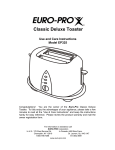
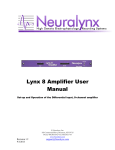
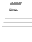
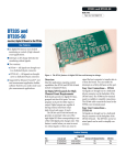
Using Signal Conditioning
Accessories with
Data Translation Boards
1
Chapter
Overview
You can use 5B and 7B signal conditioning accessories with the
following devices from Data Translation:
• DT9800-EC and DT9800-EC-I Series; refer to page 3.
• DT300 Series; refer to page 11.
• DT3000 Series; refer to page 19.
• DT3010-268 and DT3010/32-268; refer to page 27.
You can use Opto-22 signal conditioning accessories with these
boards from Data Translation:
• DT9800-EC and DT9800-EC-I Series; refer to page 3.
• DT3010-268 and DT3010/32-268; refer to page 27.
• DT335-50; refer to page 36.
This document describes how to connect signal conditioning
accessories to these boards.
2
Using Signal Conditioning Accessories with Data Translation Boards
Connecting Signal Conditioning
Accessories to the DT9800-EC and
DT9800-EC-I Series
You can use the following 5B Series, 7B Series, or Opto-22 signal
conditioning accessories with the DT9800-EC and DT9800-EC-I Series
USB modules:
• 5B01 or 5B08 backplane and 5B Series modules − The 5B01 is a
16-channel backplane; the 5B08 is an 8-channel backplane. Both
backplanes accept 5B modules for signal conditioning
applications, including measuring thermocouples, RTDs, voltage
input, current input, strain gage input, and frequency input.
To use the 5B series backplanes and modules with the DT9800-EC
or DT9800-EC-I Series, you need the following additional
accessories available from Data Translation:
− AC1315 cable −A 2-foot cable with a 26-pin connector on each
end that connects a 5B Series signal conditioning backplane to
the DT9800-EC or DT9800-EC-I Series module.
− PWR-977 power supply −A 5 V, 3 A power supply for
powering the 5B Series backplanes.
• 7BP16-1, 7BP08-1, or 7BP04-1 backplane and 7B Series
modules − The 7BP16-1 is a 16-channel backplane, the 7BP08-1 is
an 8-channel backplane, and the 7BP04-1 is a 4-channel
backplane. All three backplanes accept 7B modules for signal
conditioning applications, including measuring thermocouples,
RTDs, voltage input, current input, strain gage input, and
frequency input.
3
Chapter
To use the 7B series backplanes and modules with the DT9800-EC
or DT9800-EC-I Series, you need the following additional
accessories available from Data Translation:
− AC1315 − a 2-foot, 26-pin female to 26-pin female cable that
connects a 7B Series backplane to the AC1393 cable.
− AC1393 − a 6-inch, 26-pin male to 25-pin female adapter cable
that connects a 7B Series backplane to the AC1315 cable; the
AC1315 cable then connects to the DT9800-EC or DT9800-EC-I
Series module.
− HES14-21 power supply −A linear ac/dc power supply that
provides +24 Vdc for powering 7B Series backplanes.
• Opto-22 PB16H −The PB16H is a digital backplane that connects
to aDT9800-EC or DT9800-EC-I Series module to access the
digital I/O signals.
You need the 2.4-meter, 50-pin EP035 ribbon cable to connect the
PB16H backplane to a DT9800-EC or DT9800-EC-I Series module.
This section describes how to attach and configure these accessories
for use with a DT9800-EC or DT9800-EC-I Series module.
Note: If you also want to access the analog output, dynamic digital
output, counter/timer, and power signals on the DT9800-EC or
DT9800-EC-I Series modules, you can connect an optional AC1324
screw terminal panel, available from Data Translation, to connector
J5 on the module using an AC1315 cable. Refer to the DT9800 Series
Getting Started Manual for connection information.
4
Using Signal Conditioning Accessories with Data Translation Boards
Attaching a 5B Series Backplane
To connect a 5B Series signal conditioning backplane to a DT9800-EC
or DT9800-EC-I Series module, perform the following steps and refer
to Figure 1:
J6 Connector
USB Cable to
Host Computer
DT9800-EC/
DT9800-EC-I
5B Series Backplane
AC1315
Cable
PWR-977
Power Supply
To wall outlet
Figure 1: Connecting a 5B Series Backplane to the DT9800-EC or
DT9800-EC-I Series Modules
1.
Plug one end of an AC1315 cable into the J6 connector of the
DT9800-EC or DT9800-EC-I Series module.
2.
Plug the other end of the AC1315 cable into the 26-pin connector
on the 5B Series backplane.
3.
Connect power supply PWR-977 to the +5 V and power ground
screw terminals on the 5B Series backplane and to the wall outlet.
5
Chapter
Attaching a 7B Series Backplane
To connect a 7B Series signal conditioning backplane to a DT9800-EC
or DT9800-EC-I Series module, perform the following steps and refer
to Figure 2:
USB Cable to
Host Computer
J6 Connector
AC1393
Adapter Cable
DT9800-EC/
DT9800-EC-I
7B Series Backplane
AC1315
Cable
HES14-21
Power Supply
To wall outlet
Figure 2: Connecting a 7B Series Backplane to the DT9800-EC or
DT9800-EC-I Series Modules
6
1.
Plug one end of an AC1315 cable into the J6 connector of the
DT9800-EC or DT9800-EC-I Series module.
2.
Plug the other end of the AC1315 cable into the 26-pin connector
of the AC1393 adapter cable; then, attach the 25-pin connector of
the AC1393 adapter cable to the 7B Series backplane.
3.
Connect power supply HES14-21 to the V+A and COM screw
terminals on the 7B Series backplane and to the wall outlet.
Using Signal Conditioning Accessories with Data Translation Boards
Attaching a PB16H Opto-22 Backplane
To connect a PB16H Opto-22 backplane to a DT9800-EC or
DT9800-EC-I Series module, perform the following steps and refer to
Figure 3:
USB Cable
to Host
Computer
J4 Connector
DT9800-EC/
DT9800-EC-I
PB16H Opto-22 Backplane
EP035 50-Pin
Ribbon Cable
Figure 3: Connecting the PB16H Opto-22 Backplane to the
DT9800-EC or DT9800-EC-I Series Function Module
1.
Plug one end of an EP035 cable into the J4 connector of the
DT9800-EC or DT9800-EC-I Series module.
2.
Plug the other end of the EP035 cable into the 50-pin connector on
the PB16H Opto-22 backplane.
7
Chapter
Configuring the System
When using 5B or 7B Series signal conditioning accessories with a
DT9800-EC or DT9800-EC-I Series module, keep the following
considerations in mind:
• Configure your USB module to use single-ended mode. If you are
using a 5B Series backplane, you must also install jumper W3 on
the 5B Series backplane to connect Amp Low to Analog Ground.
• The 5B01 and 7BP16-1 map to single-ended analog input
channels 0 to 15, the 5B08 and 7BP08-1 map to single-ended
analog input channels 0 to 7, and the 7BP04-1 maps to
single-ended analog input channels 0 to 3. Therefore, if you are
using a 7BP04-1 backplane, for example, wire analog input
channels 0 to 3 to the 7BP04-1 backplane; in this configuration,
the remaining analog input channels are not accessible.
• You can determine how channels 14 and 15 are used on the 5B01
and 7BP16-1 backplanes using DIP switch block SW1 on the
DT9800-EC and DT9800-EC-I function modules. DIP switch SW1
contains switches 1 to 4.
To use channels 14 and 15 on the 5B01 or 7BP16 as analog inputs,
slide all the switches of DIP switch SW1 on the DT9800-EC or
DT9800-EC-I Series module to the OFF position. To use channel
14 on the 5B01 or 7BP16 as analog output channel 0, set switches
1 and 3 of DIP switch SW1 on the DT9800-EC or DT9800-EC-I
Series module to the ON position.
To use channel 15 on the 5B01 or 7BP16 as analog output channel
1, set switches 2 and 4 of DIP switch SW1 on the DT9800-EC or
DT9800-EC-I Series modules to the ON position.
Refer to Figure 4 for the location of DIP switch SW1.
8
Using Signal Conditioning Accessories with Data Translation Boards
SW1
OFF
1
2
3
4
Function
ON
Switch Settings
Channel 14 is an
Analog Input
Set switches 1 and
3 of SW1 OFF.
Channel 15 is an
Analog Input
Set switches 2 and
4 of SW1 OFF.
Channel 14 is an
Analog Output
Set switches 1 and
3 of SW1 ON.
Channel 15 is an
Analog Output
Set switches 2 and
4 of SW1 ON.
SW1
DT9800-EC or DT9800-EC-I
Series Function Module
J5
J6
J4
Figure 4: DIP Switch SW1
• 5B and 7B thermocouple modules provide their own CJC and
return a voltage that already compensates for CJC. Therefore,
when using 5B and 7B Series thermocouple modules, you do not
have to compensate for offsets.
• The output of many 5B modules is ±5 V. The output of many 7B
modules is 0 to 10 V. Ensure that you select an input range that
matches the output of the 5B or 7B modules that you are using.
For example, if you are using 5B modules that have an output of
±5 V, use a bipolar input range and a gain of 2 on the DT9800-EC
and DT9800-EC-I Series modules.
9
Chapter
• Connect all unused inputs to analog common. Reading an open
channel can cause settling problems on the next valid channel.
Refer to the DT9800 Series Getting Started Manual and DT9800 Series
User’s Manual, and to the user’s manuals and data sheets for the 5B
Series, 7B Series, and Opto-22 accessories for more information.
10
Using Signal Conditioning Accessories with Data Translation Boards
Connecting Signal Conditioning
Accessories to the DT300 Series
If you want to use 5B or 7B Series signal conditioning modules with
the DT300 Series, you need the following accessories, available from
Data Translation:
• STP300 screw terminal panel −Screw terminal panel with two
connectors. Connector J1 accommodates the analog and digital
I/O signals from the DT300 Series board, and connector J2 allows
you to connect 5B and 7B Series signal conditioning backplanes.
• EP305 cable −A 2-meter, twisted-pair, shielded cable that
connects the 68-pin connector (J1) on the DT300 Series board to
the J1 connector on the STP300 screw terminal panel.
• 5B01 or 5B08 backplane and 5B Series modules − The 5B01 is a
16-channel backplane; the 5B08 is an 8-channel backplane. Both
backplanes accept 5B modules for signal conditioning
applications, including measuring thermocouples, RTDs, voltage
input, current input, strain gage input, and frequency input.
To use the 5B series backplanes and modules with the STP300,
you need the following additional accessories available from
Data Translation:
− AC1315 cable −A 2-foot cable with a 26-pin connector on each
end that connects a 5B Series signal conditioning backplane to
connector J2 on the STP300 screw terminal panel.
− PWR-977 power supply −A 5 V, 3 A power supply for
powering the 5B Series backplanes.
• 7BP16-1, 7BP08-1, or 7BP04-1 backplane and 7B Series
modules − The 7BP16-1 is a 16-channel backplane, the 7BP08-1 is
an 8-channel backplane, and the 7BP04-1 is a 4-channel
backplane. All three backplanes accept 7B modules for signal
conditioning applications, including measuring thermocouples,
RTDs, voltage input, current input, strain gage input, and
frequency input.
11
Chapter
To use the 7B series backplanes and modules with the STP300,
you need the following additional accessories available from
Data Translation:
− AC1315 − a 2-foot, 26-pin female to 26-pin female cable that
connects a 7B Series backplane to the AC1393 cable.
− AC1393 − a 6-inch, 26-pin male to 25-pin female adapter cable
that connects a 7B Series backplane to the AC1315 cable; the
AC1315 cable then connects to the STP300 screw terminal
panel.
− HES14-21 power supply −A linear ac/dc power supply that
provides +24 Vdc for powering 7B Series backplanes.
This section describes how to attach and configure these accessories
for use with a DT300 Series board.
12
Using Signal Conditioning Accessories with Data Translation Boards
Attaching an STP300 Screw Terminal Panel
To attach an STP300 screw terminal panel to a DT300 Series board,
perform the following steps and refer to Figure 5:
Connector (J1)
DT300 Series
Board
EP305 Cable
J1
STP300 Screw
Terminal Panel
Figure 5: Attaching the STP300 Screw Terminal Panel to a
DT300 Series Board
1.
Plug one end of the EP305 cable into the connector J1 of the
DT300 Series board.
2.
Plug the other end of the EP305 cable into connector J1 of the
STP300 screw terminal panel.
13
Chapter
Attaching a 5B Series Backplane
To attach a 5B Series backplane to the STP300 screw terminal panel,
perform the following steps and refer to Figure 6:
J2 Connector
STP300
To DT300 Series
board
5B01 or 5B08
AC1315
Cable
PWR-977
Power Supply
To wall outlet
Figure 6: Connecting the 5B Series Backplane to the STP300
14
1.
Plug one end of the AC1315 cable into the J2 connector of the
STP300 screw terminal panel.
2.
Plug the other end of the AC1315 cable into the 26-pin connector
on the 5B Series backplane.
3.
Connect power supply PWR-977 to the +5 V and power ground
screw terminals on the 5B Series backplane and to the wall outlet.
Using Signal Conditioning Accessories with Data Translation Boards
Attaching a 7B Series Backplane
To connect a 7B Series signal conditioning backplane to the STP300,
perform the following steps and refer to Figure 2:
J2 Connector
AC1393
Adapter Cable
7BP16-1, 7BP08-1,
7BP04-1
STP300
To DT300 Series
board
AC1315
Cable
HES14-21
Power Supply
To wall outlet
Figure 7: Connecting the 7B Series Backplane to the STP300
1.
Plug one end of the AC1315 cable into the J2 connector of the
STP300 screw terminal panel.
2.
Plug the other end of the AC1315 cable into the 26-pin connector
of the AC1393 adapter cable; then, attach the 25-pin connector of
the AC1393 adapter cable to the 7B Series backplane.
3.
Connect power supply HES14-21 to the V+A and COM screw
terminals on the 7B Series backplane and to the wall outlet.
15
Chapter
Configuring the System
When using the STP300 screw terminal panel with 5B or 7B Series
signal conditioning accessories, keep the following considerations in
mind:
• Configure your DT300 Series board to use single-ended mode
(pseudo-differential inputs). You must remove jumper W1 on the
STP300. If you are using a 5B Series backplane, you must also
install jumper W3 on the 5B Series backplane o connect Amp Low
to Analog Ground.
• The 5B08 and 7BP08-1 map to single-ended analog input
channels 0 to 7, and the 7BP04-1 maps to single-ended analog
input channels 0 to 3. If you are using a signal conditioning
module for an analog input channel, ensure that you connect the
analog input signal to the module on the signal conditioning
backplane. For channels that do not use signal conditioning,
connect the analog input signals to the STP300 screw terminal
panel.
Consider the following example. Assume that you are using a
5B08 with the STP300 and that you are using 5B modules to
condition signals on analog input channels 0 to 3. In this example,
wire analog inputs to the screw terminals corresponding to
modules 0 to 3 on the 5B08 backplane. Connect the remaining
analog input signals to the appropriate screw terminals on the
STP300 screw terminal panel.
Note: You cannot use analog output modules on the 5B08,
7BP08-1, or 7BP04-1 backplane.
• By default, the 5B01 and 7BP16-1 backplanes map to
single-ended analog input channels 0 to 15. However, you can
use channels 14 and 15 on the 5B01 or 7BP16-1 backplane as
analog output channels 0 and 1.
16
Using Signal Conditioning Accessories with Data Translation Boards
When jumpers W4 to W7 are not installed on the STP300, the
5B01/7BP16-1 maps to single-ended analog input channels 0 to
15.
With jumpers W4 and W5 installed on the STP300, the
5B01/7BP16-1 maps to single-ended analog input channels 0 to
13, DAC0 at channel 14, and analog input channel 15.
With jumpers W6 and W7 installed on the STP300, the
5B01/7BP16-1 maps to single-ended analog input channels 0 to
14 and DAC1 at channel 15.
If you are using a signal conditioning module for an analog input
channel, ensure that you connect the analog input signal to the
module on the signal conditioning backplane. For channels that
do not use signal conditioning, connect the analog input signals
to the STP300 screw terminal panel.
Consider the following example. Assume that you are using a
5B01 with the STP300 and that you are using 7B modules to
condition signals on analog input channels 0 to 5 and analog
output channel 1. In this example, wire analog inputs to the
screw terminals corresponding to analog input channels 0 to 5 on
the 5B01 backplane. Wire analog output signals to channel 15 on
the 5B01 backplane, ensuring that jumpers W6 and W7 are
installed on the STP300 screw terminal panel. Connect the
remaining analog I/O signals to the appropriate terminals on the
STP300 screw terminal panel.
• 5B and 7B thermocouple modules provide their own CJC and
return a voltage that already compensates for CJC. Therefore,
when using 5B and 7B Series thermocouple modules, you do not
have to compensate for offsets.
• The output of many 5B modules is ±5 V. The output of many 7B
modules is 0 to 10 V. Ensure that you select an input range that
matches the output of the 5B or 7B modules that you are using.
For example, if you are using 5B modules that have an output of
±5 V, use a bipolar input range and a gain of 2 on the DT300
Series board.
17
Chapter
• Connect all unused inputs to analog common. Reading an open
channel can cause settling problems on the next valid channel.
Refer to the DT300 Series Getting Started Manual and DT300 Series
User’s Manual, and to the user’s manuals and data sheets for the 5B
and 7B Series for more information.
18
Using Signal Conditioning Accessories with Data Translation Boards
Connecting Signal Conditioning
Accessories to the DT3000 Series
If you want to use 5B or 7B Series signal conditioning modules with
the DT3000 Series, you need the following accessories, available from
Data Translation:
• DT730 or DT730-T screw terminal panel −General-purpose
screw terminal panel providing analog, digital, counter/timer,
external trigger, and external clock connections. The DT730-T is
the same as the DT730, but also provides cold-junction
compensation for thermocouple connections. Connector J1
accommodates the analog and digital I/O signals from the
DT3000 Series board; connector J2 allows you to connect 5B and
7B signal conditioning backplanes.
• EP291 cable −A 0.95 m (3.2-foot) cable with two 100-pin
connectors that connects the J1 connector on a DT3000 Series
board to the J1 connector on the DT730 or DT730-T screw
terminal panel.
• 5B01 or 5B08 backplane and 5B Series modules − The 5B01 is a
16-channel backplane; the 5B08 is an 8-channel backplane. Both
backplanes accept 5B modules for signal conditioning
applications, including measuring thermocouples, RTDs, voltage
input, current input, strain gage input, and frequency input.
To use the 5B series backplanes and modules with the DT730 or
DT730-T screw terminal panel, you need the following additional
accessories available from Data Translation:
− AC1315 cable −A 2-foot cable with a 26-pin connector on each
end that connects a 5B Series signal conditioning backplane to
the DT730 or DT730-T screw terminal panel.
− PWR-977 power supply −A 5 V, 3 A power supply for
powering the 5B Series backplanes.
19
Chapter
• 7BP16-1, 7BP08-1, or 7BP04-1 backplane and 7B Series
modules − The 7BP16-1 is a 16-channel backplane, the 7BP08-1 is
an 8-channel backplane, and the 7BP04-1 is a 4-channel
backplane. All three backplanes accept 7B modules for signal
conditioning applications, including measuring thermocouples,
RTDs, voltage input, current input, strain gage input, and
frequency input.
To use the 7B series backplanes and modules with the DT730 or
DT730-T, you need the following additional accessories available
from Data Translation:
− AC1315 − a 2-foot, 26-pin female to 26-pin female cable that
connects a 7B Series backplane to the AC1393 cable.
− AC1393 − a 6-inch, 26-pin male to 25-pin female adapter cable
that connects a 7B Series backplane to the AC1315 cable; the
AC1315 cable then connects to the DT730 or DT730-T screw
terminal panel.
− HES14-21 power supply −A linear ac/dc power supply that
provides +24 Vdc for powering 7B Series backplanes.
This section describes how to attach and configure these accessories
for use with a DT3000 Series board.
20
Using Signal Conditioning Accessories with Data Translation Boards
Attaching a DT730 or DT730-T Screw Terminal
Panel
To connect the DT730 or DT730-T screw terminal panel to a DT3000
Series board, perform the following steps and refer to Figure 8:
DT3000 Series Board
Rear Panel Connector
J1 Connector
Ferrite Clamp
Computer
(Side View)
EP291 Cable
DT730 or
DT730-T
Figure 8: Connecting the DT730 or DT730-T to the DT3000 Series Board
1.
Plug one end of the EP291 flat ribbon cable into the connector at
the rear of the DT3000 Series board and the other end into the
DT730 or DT730-T.
2.
To reduce EMI emissions, place the ferrite clamp, shipped with
the DT3000 Series board, no more than six inches from the
DT3000 Series board connector. The ferrite clamp attaches to the
cable with an integral latch and grips the cable to prevent sliding.
21
Chapter
Attaching a 5B Series Backplane
To connect a 5B Series signal conditioning backplane to the DT730 or
DT730-T screw terminal panel, perform the following steps and refer
to Figure 9:
J2 Connector
DT730 or
DT730-T
To DT3000
Series board
5B01 or 5B08
AC1315
Cable
PWR-977
Power Supply
To wall outlet
Figure 9: Connecting the 5B Series Backplane to the
DT730 or DT730-T Screw Terminal Panel
22
1.
Plug one end of the AC1315 cable into the J2 connector of the
DT730 or DT730-T screw terminal panel.
2.
Plug the other end of the AC1315 cable into the 26-pin connector
on the 5B Series backplane.
3.
Connect power supply PWR-977 to the +5 V and power ground
screw terminals on the 5B Series backplane and to the wall outlet.
Using Signal Conditioning Accessories with Data Translation Boards
Attaching a 7B Series Backplane
To connect a 7B Series signal conditioning backplane to the DT730 or
DT730-T screw terminal panel, perform the following steps and refer
to Figure 10:
J2 Connector
AC1393
Adapter Cable
DT730 or
DT730-T
To DT3000
Series board
7BP16-1, 7BP08-1,
7BP04-1
AC1315
Cable
HES14-21
Power Supply
To wall outlet
Figure 10: Connecting the 7B Series Backplane to the DT730 or DT730-T
Screw Terminal Panel
1.
Plug one end of the AC1315 cable into the J2 connector of the
DT730 or DT730-T screw terminal panel.
2.
Plug the other end of the AC1315 cable into the 26-pin connector
of the AC1393 adapter cable; then, attach the 25-pin connector of
the AC1393 adapter cable to the 7B Series backplane.
3.
Connect power supply HES14-21 to the V+A and COM screw
terminals on the 7B Series backplane and to the wall outlet.
23
Chapter
Configuring the System
When using the DT730 or DT730-T screw terminal panel with 5B or
7B Series signal conditioning accessories, keep the following
considerations in mind:
• Configure your DT3000 Series board to use single-ended mode
(pseudo-differential inputs). You must remove jumper W1 on the
DT730 or DT730-T. If you are using a 5B Series backplane, you
must also install jumper W3 on the 5B Series backplane to
connect Amp Low to Analog Ground.
• The 5B08 and 7BP08-1 map to single-ended analog input
channels 0 to 7, and the 7BP04-1 maps to single-ended analog
input channels 0 to 3. If you are using a signal conditioning
module for an analog input channel, ensure that you connect the
analog input signal to the module on the signal conditioning
backplane. For channels that do not use signal conditioning,
connect the analog input signals to the DT730 or DT730-T screw
terminal panel.
Consider the following example. Assume that you are using a
5B08 with the DT730 and that you are using 5B modules to
condition signals on analog input channels 0 to 3. In this example,
wire analog inputs to the screw terminals corresponding to
channels 0 to 3 on the 5B08 backplane. Connect the remaining
analog input signals to the appropriate screw terminals on the
DT730 screw terminal panel.
Note: You cannot use analog output modules on the 5B08,
7BP08-1, or 7BP04-1 backplane.
• By default, the 5B01 and 7BP16-1 backplanes map to
single-ended analog input channels 0 to 15. However, you can
use channels 14 and 15 on the 5B01 or 7BP16-1 backplane as
analog output channels 0 and 1.
24
Using Signal Conditioning Accessories with Data Translation Boards
When jumpers W4 to W7 are not installed on the
DT730/DT730-T screw terminal panel, the 5B01/7BP16-1 maps
to single-ended analog input channels 0 to 15.
With jumpers W4 and W5 installed on the DT730/DT730-T, the
5B01/7BP16-1 maps to single-ended analog input channels 0 to
13, DAC0 at channel 14, and analog input channel 15.
With jumpers W6 and W7 installed on the DT730/DT730-T, the
5B01/7BP16-1 maps to single-ended analog input channels 0 to
14 and DAC1 at channel 15.
If you are using a signal conditioning module for an analog input
channel, ensure that you connect the analog input signal to the
module on the signal conditioning backplane. For channels that
do not use signal conditioning, connect the analog input signals
to the DT730 or DT730-T screw terminal panel.
Consider the following example. Assume that you are using a
5B01 with the DT730 and that you are using 7B modules to
condition signals on analog input channels 0 to 5 and analog
output channel 1. In this example, wire analog inputs to the
screw terminals corresponding to analog input channels 0 to 5 on
the 5B01 backplane. Wire analog output signals to channel 15 on
the 5B01 backplane, ensuring that jumpers W6 and W7 are
installed on the DT730 screw terminal panel. Connect the
remaining analog I/O signals to the appropriate terminals on the
DT730 screw terminal panel.
• The DT730-T screw terminal panel is provided for thermocouple
connections and includes a CJC circuit for measuring
temperature at the connector blocks on the screw terminal panel.
To measure thermocouples with the DT730-T directly, you must
scale the voltage for the gain and thermocouple type, and add
this voltage to the thermocouple voltage to remove the offset
created by the temperature of the screw terminal panel.
25
Chapter
If you use 5B/7B thermocouple module, the 5B/7B module
returns a voltage that already compensates for the CJC.
Therefore, if you are using the DT730-T with 5B modules, you do
not have to compensate for offsets as you do when measuring
thermocouples on the DT730-T directly.
• The output of many 5B modules is ±5 V. The output of many 7B
modules is 0 to 10 V. Ensure that you select an input range that
matches the output of the 5B or 7B modules that you are using.
For example, if you are using 5B modules that have an output of
±5 V, use a bipolar input range and a gain of 2 on the DT3000
Series board.
• Connect all unused inputs to analog common. Reading an open
channel can cause settling problems on the next valid channel.
Refer to the DT3000 Series Getting Started Manual and DT3000 Series
User’s Manual, and to the user’s manuals and data sheets for the 5B
and 7B Series for more information.
26
Using Signal Conditioning Accessories with Data Translation Boards
Connecting Signal Conditioning
Accessories to a DT3010-268 or
DT3010/32-268 Board
If you want to use 5B Series, 7B Series, or Opto-22 signal conditioning
accessories with the DT3010-268 or DT3010/32-268 board, you need
the following accessories, available from Data Translation:
• STP268-EC screw terminal panel −Screw terminal panel with
two 26-pin connectors for attaching to 5B or 7B Series signal
conditioning backplanes, one 50-pin connector for attaching to an
Opto-22 PB16H backplane, and one 68-pin connector for
attaching to the DT3010-268 or DT3010/32-268 board.
• EP324 cable −A 1 1/2-inch ribbon cable that connects to the
68-pin digital I/O connector (J2) on the DT3010-268 or
DT3010/32-268 board; the other end of this cable provides a
68-pin connector and face plate for connection to an EP325 cable.
This cable is shipped with each DT3010-268 or DT3010/32-268
board.
• EP325 cable −A, 6-foot, SCSI-3 cable that connects the STP268 or
STP268-EC screw terminal panel to connector J1 on the
DT3010-268 board.
• 5B01 or 5B08 backplane and 5B Series modules − The 5B01 is a
16-channel backplane; the 5B08 is an 8-channel backplane. Both
backplanes accept 5B modules for signal conditioning
applications, including measuring thermocouples, RTDs, voltage
input, current input, strain gage input, and frequency input.
To use the 5B series backplanes and modules with the
STP268-EC, you need the following additional accessories
available from Data Translation:
− AC1315 cable −A 2-foot cable with a 26-pin connector on each
end that connects a 5B Series signal conditioning backplane to
connector J2 on the STP268-EC screw terminal panel.
27
Chapter
− PWR-977 power supply −A 5 V, 3 A power supply for
powering the 5B Series backplanes.
• 7BP16-1, 7BP08-1, or 7BP04-1 backplane and 7B Series
modules − The 7BP16-1 is a 16-channel backplane, the 7BP08-1 is
an 8-channel backplane, and the 7BP04-1 is a 4-channel
backplane. All three backplanes accept 7B modules for signal
conditioning applications, including measuring thermocouples,
RTDs, voltage input, current input, strain gage input, and
frequency input.
To use the 7B series backplanes and modules with the
STP268-EC, you need the following additional accessories
available from Data Translation:
− AC1315 − a 2-foot, 26-pin female to 26-pin female cable that
connects a 7B Series backplane to the AC1393 cable.
− AC1393 − a 6-inch, 26-pin male to 25-pin female adapter cable
that connects a 7B Series backplane to the AC1315 cable; the
AC1315 cable then connects to a STP268-EC screw terminal
panel.
− HES14-21 power supply −A linear ac/dc power supply that
provides +24 Vdc for powering 7B Series backplanes.
• Opto-22 PB16H −The PB16H is a digital backplane that connects
to the STP268-EC screw terminal panel to access the digital I/O
signals.
You need the 2.4-meter, 50-pin EP035 ribbon cable to connect the
PB16H backplane to the STP268-EC screw terminal panel.
This section describes how to attach and configure these accessories
for use with a DT3010-268 and DT3010/32-268 boards.
28
Using Signal Conditioning Accessories with Data Translation Boards
Attaching the STP268-EC Screw Terminal Panel
To connect the STP268-EC screw terminal panel to a DT3010-268 or
DT3010/32-268 board, perform the following steps and refer to
Figure 11:
Connector J1
EP325 Cable
DT3010-268 or
DT3010/32-268
Board
J1
STP268-EC
Screw Terminal
Panel
Figure 11: Attaching an STP268-EC Screw Terminal Panel to the
DT3010-268 or DT3010/32-268 Board
1.
Plug one end of the EP325 cable into the connector at the rear of
the DT3010-268 or DT3010/32-268 board.
2.
Connect the other end of the EP325 cable into connector J1 of the
STP268-EC screw terminal panel.
29
Chapter
Attaching a 5B Series Backplane
To connect a 5B Series signal conditioning backplane to the
STP268-EC screw terminal panel, perform the following steps and
refer to Figure 12:
DT3010-268 or
DT3010/32-268
Board
J1 Connector
J3 or J4 Connector
5B01 or 5B08
STP268-EC
EP325
Cable
AC1315
Cable
PWR-977
Power Supply
To wall outlet
Figure 12: Connecting the 5B Series Backplane to the
STP268-EC Screw Terminal Panel
30
1.
Plug one end of an AC1315 cable into the J3 or J4 connector of the
STP268-EC screw terminal panel.
2.
Plug the other end of the AC1315 cable into the 26-pin connector
on the 5B Series backplane.
3.
Connect power supply PWR-977 to the +5 V and power ground
screw terminals on the 5B Series backplane and to the wall outlet.
Using Signal Conditioning Accessories with Data Translation Boards
Attaching a 7B Series Backplane
To connect a 7B Series signal conditioning backplane to the
STP268-EC screw terminal panel, perform the following steps while
referring to Figure 13:
DT3010-268 or
DT3010/32-268
Board
J3 or J4 Connector
J1 Connector
AC1393
Adapter Cable
7B Series
Backplane
STP268-EC
EP325
Cable
AC1315
Cable
Figure 13: Connecting the 7B Series Backplane to the STP268-EC
Screw Terminal Panel
1.
Plug one end of an AC1315 cable into the J3 or J4 connector of the
STP268-EC screw terminal panel.
2.
Plug the other end of the AC1315 cable into the 26-pin connector
of the AC1393 adapter cable; then, attach the 25-pin connector of
the AC1393 adapter cable to the 7B Series backplane.
3.
Connect power supply HES14-21 to the V+A and COM screw
terminals on the 7B Series backplane and to the wall outlet.
31
Chapter
Attaching a PB16H Opto-22 Backplane
To connect a PB16H Opto-22 backplane to a STP268-EC screw
terminal panel, perform the following steps while referring to Figure
14:
DT3010-268 or
DT3010/32-268
Board
J1 Connector
J2 Connector
PB16H Opto-22
Backplane
STP268-EC
EP325
Cable
EP035 50-Pin
Ribbon Cable
Figure 14: Connecting the PB16H Opto-22 Backplane to the
DT9800-EC or DT9800-EC-I Series Function Module
32
1.
Plug one end of an EP035 cable into the J2 connector of the
STP268-EC screw terminal panel.
2.
Plug the other end of the EP035 cable into the 50-pin connector on
the PB16H Opto-22 backplane.
Using Signal Conditioning Accessories with Data Translation Boards
Configuring the System
When using the STP268-EC screw terminal panel with 5B or 7B Series
signal conditioning accessories, keep the following considerations in
mind:
• Configure your DT3010-268 or DT3010/32-268 board to use
single-ended mode. If you are using a 5B Series backplane, you
must install jumper W3 on the 5B Series backplane to connect
Amp Low to Analog Ground.
• The 5B08 and 7BP08-1 backplanes map to single-ended analog
input channels 0 to 7, and the 7BP04-1 backplane maps to
single-ended analog input channels 0 to 3. If you are using a
signal conditioning module for an analog input channel, ensure
that you connect the analog input signal to the module on the
signal conditioning backplane. For channels that do not use
signal conditioning, connect the analog input signals to the
STP268-EC screw terminal panel.
Consider the following example. Assume that you are using a
5B08 with the ST268-EC and that you are using 5B modules to
condition signals on analog input channels 0 to 3. In this example,
wire analog inputs to the screw terminals corresponding to
channels 0 to 3 on the 5B08 backplane. Connect the remaining
analog input signals to the appropriate screw terminals on the
STP268-EC screw terminal panel.
Note: You cannot use analog output modules on the 5B08,
7BP08-1, or 7BP04-1 backplane.
• By default, the 5B01 and 7BP16-1 backplanes map to
single-ended analog input channels 0 to 15. However, you can
use channels 14 and 15 on the 5B01 or 7BP16-1 backplane as
analog output channels 0 and 1.
33
Chapter
When jumpers W1 to W4 are not installed on the STP268-EC
screw terminal panel, the 5B01/7BP16-1 maps to single-ended
analog input channels 0 to 15.
With jumpers W1 and W2 installed on the STP268-EC, the
5B01/7BP16-1 maps to single-ended analog input channels 0 to
13, DAC0 at channel 14, and analog input channel 15.
With jumpers W3 and W4 installed on the STP268-EC, the
5B01/7BP16-1 maps to single-ended analog input channels 0 to
14 and DAC1 at channel 15.
If you are using a signal conditioning module for an analog input
channel, ensure that you connect the analog input signal to the
module on the signal conditioning backplane. For channels that
do not use signal conditioning, connect the analog input signals
to the STP268-EC screw terminal panel.
Consider the following example. Assume that you are using a
5B01 with the STP268-EC and that you are using 5B modules to
condition signals on analog input channels 0 to 5 and analog
output channel 1. In this example, wire analog inputs to the
screw terminals corresponding to analog input channels 0 to 5 on
the 5B01 backplane. Wire analog output signals to channel 15 on
the 5B01 backplane, ensuring that jumpers W6 and W7 are
installed on the STP268-EC screw terminal panel. Connect the
remaining analog I/O signals to the appropriate terminals on the
STP268-EC screw terminal panel.
• 5B and 7B thermocouple modules provide their own CJC and
return a voltage that already compensates for CJC. Therefore,
when using 5B or 7B thermocouple modules, you do not have to
compensate for offsets.
• The output of many 5B modules is ±5 V. The output of many 7B
modules is 0 to 10 V. Ensure that you select an input range that
matches the output of the 5B or 7B modules that you are using.
For example, if you are using 5B modules that have an output of
±5 V, use a bipolar input range and a gain of 2 on the DT3010-268
or DT3010/32-268 board.
34
Using Signal Conditioning Accessories with Data Translation Boards
• Connect all unused inputs to analog common. Reading an open
channel can cause settling problems on the next valid channel.
Refer to the DT3010 Getting Started Manual, DT3010 Series User’s
Manual, and to the user’s manuals and data sheets for the 5B Series,
7B Series, and Opto-22 accessories for more information.
35
Chapter
Connecting Signal Conditioning
Accessories to the DT335-50 Board
If you want to use signal conditioning accessories with the DT335-50
board, you need the following accessories, available from Data
Translation:
• EP195 paddle board– A board with three 50-pin connectors used
to attach an DT335-50 board to two Opto-22 PB16A backplanes.
This paddle board requires an EP035 cable and two EP036 cables.
• EP035 −A 2.4-meter, 50-pin, flat ribbon cable that connects the
50-pin connector (J1) on DT335-50 board to the 50-pin J1
connector on the EP195 paddle board.
• Opto-22 PB16A −The PB16A is a digital backplane that connects
to the EP195 paddle board to access the digital I/O signals.
You need the 2.4-meter, 50-pin, EP036 ribbon cable to connect the
50-pin J2 or J3 connector of the EP195 to the 50-pin edge
connector on the Opto-22 PB16A backplane. To connect two
Opto 22 PB16A backplanes to the EP195 paddle board, two EP036
cables are required.
This section describes how to attach and configure these accessories
for use with a DT3335-50 board.
36
Using Signal Conditioning Accessories with Data Translation Boards
Attaching the EP195 Paddle Board
To connect the EP195 paddle board to an DT335-50 board, perform
the following steps while referring to Figure 15:
J2
DT335-50 Board
J1
EP035 Cable
J1
J3
EP195 Paddle
Board
Figure 15: Attaching an EP195 Paddle Board to the EP335-50 Board
1.
Plug one end of the EP035 cable into connector J1 of the DT335-50
board.
2.
Connect the other end of the EP035 cable into connector J1 of the
EP195 paddle board.
37
Chapter
Attaching a PB16A Opto-22 Backplane
To connect up to two PB16A Opto-22 backplanes to the EP195 paddle
board, perform the following steps while referring to Figure 3:
Ports A and B
DT335-50 Board
J1
EP035 Cable
J2
EP036 Cable
Opto -22 PB16A
Backplane
J3
EP036 Cable
Opto-22 PB16A
Backplane
J1
EP195 Paddle
Board
Ports C and D
Figure 16: Connecting the PB16H Opto-22 Backplane to the
EP195 Paddle Board
1.
Plug one end of an EP036 cable into the J2 connector of the
EP195 paddle board.
2.
Plug the other end of the EP036 cable into the 50-pin connector of
a PB16A Opto-22 backplane.
3.
If you want to attach another Opto-22 PB16A backplane, use
another EP036 cable and plug one end of this cable into the J3
connector of the EP195 paddle board and the other end into the
50-pin connector of the second PB16A Opto-22 backplane.
Note: Connector J2 on the EP195 brings out digital I/O ports A and
B of the DT335-50 board. Connector J3 on the EP195 brings out
digital I/O ports C and D of the DT335-50 board.
38