1
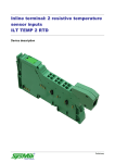
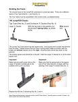
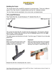
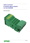
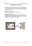
Inline Terminal: ILT DALI/MM Device Description Preliminary Disclaimer / Imprint This manual is intended to provide support for installation and usage of the device. The information is believed to be accurate and reliable. However, SysMik GmbH Dresden assumes no responsibility for possible mistakes and deviations in the technical specifications. SysMik GmbH Dresden reserves the right to make modifications in the interest of technical progress to improve our modules and software or to correct mistakes. We are grateful to you for criticism and suggestions. Further information (device description, available software) can be found on our homepage www.sysmik.de. Please ask for latest information. SysMik disclaims all warranties in case of improper use or disassembly and software modifications not described in this document or when using improper or faulty tools. Commissioning and operation of the device by qualified personnel only. All applicable regulations have to be observed. SysMik® and the SysMik logo are registered trademarks of SysMik GmbH Dresden. IPOCS™ is trademark © of SysMik GmbH Dresden. "Networking Together!" is subject to copyright of SysMik GmbH Dresden. All other trademarks mentioned in this document are registered properties of their owners. These and further trademarks are used in this document but not marked for better readability. No part of this document may be reproduced or modified in any form without prior written agreement with SysMik GmbH Dresden. Copyright © 2014 by SysMik GmbH Dresden SysMik GmbH Dresden Tel + 49 (0) 351 – 4 33 58 – _0 Bertolt-Brecht-Allee 24 Fax + 49 (0) 351 – 4 33 58 – 29 01309 Dresden E-Mail (Sales) E-Mail (Support) Germany 2 Homepage sysmik.de [email protected] [email protected] www.sysmik.de ILT DALI/MM Content Content ILT-DALI/MM Device Description 1 Content 3 1 Overview 4 2 Order Information 4 3 Connections 5 3.1 Wiring Guidelines 6 3.2 Wiring Example 7 3.3 Typical Terminal Arrangement 8 4 Communication 9 4.1 Programming Data / Configuration Data 9 4.2 4.2.1 4.2.2 4.2.3 4.2.4 Process Data Structure Basic Commands DALI Commands Transferring DALI Packets from the Terminal to the Interbus Master Example Control 9 12 13 15 15 5 Technical Data 16 6 Literature 18 sysmik.de 3 Overview / Order Information 1 Overview The terminal ILT DALI/MM is a multi-master capable DALI master for the modular Inline I/O system of Phoenix Contact. It is used to control lamps via DALI ballasts according to IEC 62386 (replacing IEC 60929). In addition, the terminal supports multi master operation for communication with Tridonic’s MSensors. The integrated DALI bus supply requires a 24 V DC supply, which is automatically provided by the potential routing contact UM, or alternatively via connector 1. Features: DALI master with integrated DALI bus supply sending and receiving of 2- and 3-byte DALI commands DALI supply switchable designed for both multi master and single master operation safe isolation of the DALI bus DALI bus protected against mistakenly connecting mains (up to 250 V AC) communication on local bus via process data indicators for diagnostics, transmission and reception Note: The terminal ILT DALI/MM cannot be used to supply DALI extension terminals ILT DALI (part no. 1225-100252-05-3). This description is only valid in association with the user manual IL SYS INST UM E of Phoenix Contact (see [1]). 2 Order Information Device Part number ILT DALI/MM 1225-100361-04-5 Table 2.1: Order information 4 sysmik.de ILT DALI/MM Connections 3 Connections D RxD TxD DALI / MM 1 2 3 1.1 2.1 1.2 2.2 1.3 2.3 1.4 2.4 4 Fig. 3.1: Terminal connections Indicator Color Description D RxD TxD bus diagnostics terminal is receiving data from DALI bus terminal is sending data to DALI bus green yellow yellow Table 3.1: Local diagnostic and status indicators Terminal Signal Assignment Point Connector 1 T a1.1, 2.1 b l e1.2, 2.2 US UM GND 31.3, 2.3 . 1.4, 2.4 FE 2Connector 2 : +24 V segment supply, internally connected to potential routing contact US +24 V main supply, internally connected to potential routing contact UM, 1) supply of the terminal 1) ground of 24 V supply functional earth, internally connected to potential routing contact FE unused TConnector 3 e 1.2, 2.2 DA+ DALI-Bus (positive) r 1.3, 2.3 DADALI-Bus (negative) m i Connector 4 n unused a l 1) If there is no 24 V segment on the left side of the terminal, the terminal can be supplied at this terminal points Table 3.2: Terminal point assignment Note: Terminal points not defined in table 3.2 must not be used. ILT-DALI/MM sysmik.de 5 Connections Local bus Local bus OPC UL+ UANA UL- UL+ UANA UL- 7,5V µC 5V Rx Tx UDALI 24V +24 V (US) DA+ +24 V (UM) DA- OPC µC +24 V (US) +24 V (UM) UDALI Protocol chip 24V DC/DC converter with electrical insulation Microcontroller Optocoupler Indicator LED DALI driver DC/DC converter Double / reinforced insulation 7,5V 5V Fig. 3.2: Functional overview 3.1 Wiring Guidelines The voltage drop between transmitter and receiver on the DALI bus must not exceed 2 V at 250 mA. Table 3.1.1 shows wiring recommendations. The maximum lead length between two connected DALI devices should not exceed 300 m. Lead length Minimum cross section < 100 m 100 m to 150 m > 150 m to 300 m 0.5 mm² (AWG 20) 0.75 mm² (AWG 18) 1.5 mm² (AWG 15) Table 3.1.1: Recommended cross sections of DALI bus wiring Special bus cables (twisted or shielded) are not needed. Linear, star shaped and mixed structures are applicable. Ring shaped structures should be avoided. DALI interface insulation of the electronic ballasts fulfills the requirements of base insulation only. Therefore, SELV (Safety Extra Low Voltage) is not granted on the DALI bus. Note: It is possible to use an external DALI supply. In this case, the built-in supply must not be switched on in order to keep the maximum short circuit current below 250 mA. Otherwise, connected DALI devices are overloaded and might be damaged. 6 sysmik.de ILT DALI/MM Connections 3.2 Wiring Example 1 2 3 4 D RxD TxD DALI/MM US UM GND FE 1.1 2.1 1.1 2.1 1.2 2.2 1.2 2.2 1.3 2.3 1.3 2.3 1.4 2.4 1.4 2.4 DA+ DA- DALI-Bus Fig. 3.2.1: Wiring example As long as the terminal is connected to a previous 24 V segment, it gets its supply from UM. Otherwise, there is the opportunity to supply the terminal at connectors on the first segment 1.2 / UM und 1.3 / GND (see table 3.2). ILT-DALI/MM sysmik.de 7 Connections 3.3 Typical Terminal Arrangement 1 2 1 D 2 DI2 3 D RxD 4 D RxD 5 D D RxD TxD TxD TxD DALI/MM DALI/MM DALI/MM AI/TEMP 4 RTD 1.1 2.1 1.1 2.1 1.1 2.1 1.1 2.1 1.1 2.1 1.1 2.1 1.1 2.1 1.1 2.1 1.2 2.2 1.2 2.2 1.2 2.2 1.2 2.2 1.2 2.2 1.2 2.2 1.2 2.2 1.2 2.2 1.3 2.3 1.3 2.3 1.3 2.3 1.3 2.3 1.3 2.3 1.3 2.3 1.3 2.3 1.3 2.3 1.4 2.4 1.4 2.4 1.4 2.4 1.4 2.4 1.4 2.4 1.4 2.4 1.4 2.4 1.4 2.4 1.5 2.5 1.6 2.6 Fig. 3.3.1: Typical Inline station with several DALI terminals The terminal ILT DAL/MM does not interrupt any Inline supply circuit (UM, US, UANA, UL and FE) and it provides an intermediate, not touch-proof voltage segment (grey terminal area). The 24 V – segment on the left side continues seamlessly behind the terminal. Thus, sections 1 and 5 (see fig. 3.3.1) are in the same segment. The DALI terminals should be placed preferably at the end of an Inline station but still before analog terminals in order to keep the current from UM and US through the terminals and the resulting power dissipation as small as possible. 8 sysmik.de ILT DALI/MM Communication 4 Communication 4.1 Programming Data / Configuration Data Attribute Value ID code Length code Input address area Output address area Parameter channel (PCP) Register length (Bus) BFhex (191dez) 04hex 8 Byte (4 words) 8 Byte (4 words) 0 8 Byte (4 words) Table 4.1.1: INTERBUS programming data / configuration data 4.2 Process Data Structure The terminal is unconfigured after reset and reports this to the Interbus master (bit CF = 0). The power supply is off in unconfigured state. The master has to configure the DALI mode of the terminal first. The command set is divided in basic commands (0 ≤ CMD ≤ 7) and DALI commands (8 ≤ CMD ≤ 15). Input process data IN1 contains 4 bits (CTA, CF, PWR, TYP), which have always the same meaning, regardless of the mode. All other bits have a different meaning for basic and DALI commands. Bit TYP indicates the type of input process data. The terminal accepts new commands only when the output process data word OUT1 has changed. So, every new command should change the toggle bit CT. This bit is mirrored by the terminal in bit CTA of IN1 and acknowledges the reception of this command. All reserved and unused bits have to be set to 0. 9 sysmik.de ILT DALI/MM Communication Output process data word OUT1 Bit 15 Name CT 14:12 11:10 PAR 9:6 4:0 CMD Description command toggle – toggle bit to mark new commands; has to be set to 1 for the first command (because the terminal first delivers 0) and has then to be changed for every new command reserved parameter – depending on CMD for CMD = 2 (configure terminal) 0 DALI mode 1-3 reserved reserved command basic commands 0 no command 1 read configuration 2 set configuration 3 read firmware version 4 switch bus supply on 5 switch bus supply off 6, 7 reserved DALI commands (only in DALI mode) 8 no command (just reading) 9 send DALI packet 10 force end of INITIALISE state 11 clear receive buffer 12 clear transmit buffer 13-15 reserved 16-31 reserved Table 4.2.1: Structure of output process data word OUT1 Output process data word OUT1 15 CT 14 13 0 12 11 10 PAR 9 8 7 0 6 5 4 3 2 1 CMD 0 Table 4.2.2: Structure of output process data word OUT1 – bit overview 10 sysmik.de ILT DALI/MM Communication Input process data word IN1 Bit Name Description Commonly valid bits 15 CTA 14 13 12 CF PWR TYP command toggle acknowledge – toggle bit for acknowledging commands; 0 after reset configured –terminal is configured; 0 after reset power on – bus supply ok type of input process data 0 – answer to basic commands 1 – DALI packet TYP = 0: Specific bits for basic commands 11:10 9:5 4:0 PARA CMDA output parameter reserved mirroring of command TYP = 1: Specific bits for DALI mode 11 TF 10 RF 9 INI 8 FD 7:6 RL 5 4:2 SS RP 1:0 AW transmit buffer full – starting a transmission when this bit is set might discard the previous sending command (but not necessarily so) Note: the current state should only be evaluated when the previous DALI command has been received by the terminal (that is CTA == CT), otherwise it may still be 0 receive buffer full – no further transmissions to the DALI bus are allowed when this bit is set initialised – terminal is in the INITIALISED state and cannot send DALI packets for a period of15 minutes; all transmit buffers are cleared and new transmissions are discarded frame dropped – previous to this packet one or more incoming packets were dropped (buffer overrun or after reset) length – length of DALI packet: 0 – no packet 1 – frame error (no length associated) 2 – 2-byte packet 3 – 3-byte packet self-sent – packet has been sent by this terminal receive priority – priority of received packet 0 – priority 0: 12 ms (>11,5 ms to 12,5 ms) 1 – priority 1: 13 ms (>12,5 ms to 13,5 ms) 2 – priority 2: 14 ms (>13,5 ms to 14,5 ms) 3 – priority 3: 15 ms (>14,5 ms to 15,5 ms) 4 – priority 4: 16 ms (>15,5 ms) 7 – invalid priority (≤11,5 ms) answer – answer belonging to packet 0 – no answer 1 – valid answer 2 – invalid answer 3 – only answer, without query ("orphaned"), RL = 1 Table 4.2.3: Structure of input process data word IN1 ILT-DALI/MM sysmik.de 11 Communication Input process data word IN1 15 14 13 12 CTA CF PWR 0 11 10 9 8 PARA 7 6 5 4 3 0 2 1 0 CMDA Table 4.2.4: Structure of input process data word IN1 – bit overview for basic commands Input process data word IN1 15 14 13 12 11 10 9 8 CTA CF PWR 1 TF RF INI FD 7 6 RL 5 SS 4 3 2 RP 1 0 AW Table 4.2.5: Structure of input process data word IN1 – bit overview for DALI commands 4.2.1 Basic Commands The basic commands comprise CMD = 0 - 7 and are mirrored in CMDA in IN1. Additionally, the status bits CF and PWR are merged Reading the configuration delivers the current mode in PARA, using the same encoding as PAR when writing the configuration. Reading configuration is only valid, when the terminal is already configured (CF = 1). All other basic commands deliver PARA = 0. The output process data words OUT2, OUT3 and OUT4 are not used for basic commands and have to be set to zero. The input process data words IN2, IN3 and IN4 are set to zero for all basic commands, except for reading the firmware version, which is delivered in IN2. 12 sysmik.de ILT DALI/MM Communication 4.2.2 DALI Commands Usage of process data words OUT2-OUT4 in DALI mode (TYP = 1) CMD Command no command (just receive) OUT2 9 send DALI packet 10 11 12 quit INITIALISE state clear all receive buffers clear all transmit buffers RX packet acknowledge 8 OUT3 OUT4 0 0 data bytes 1, 2 0 0 0 data byte 3, control 0 0 0 Table 4.2.2.1: Usage of output process data words OUT2-OUT4 for DALI commands Output process data word OUT2 15 14 13 12 11 10 9 8 7 6 timestamp of packet in ms 5 4 3 2 1 0 index Table 4.2.2.2: Structure of output process data word OUT2 in DALI mode Output process data word OUT3 15 14 13 12 11 10 data byte 2 (TD2) 9 8 7 6 5 4 3 2 data byte 1 (TD1) 1 0 6 5 4 3 2 1 when L = 1: data byte 3 (TD3) when L = 0: 0 0 Table 4.2.2.3: Structure of output process data word OUT3 for CMD = 9 Output process data word OUT4 15 14 13 D B L 12 11 0 10 9 8 priority TP 7 Table 4.2.2.4: Structure of output process data word OUT4 for CMD = 9 Typical use of fields in OUT4 DALI system Single master Multi master normal operation management normal operation management Field D 0 X 0 X B 0 0 0 X L 0 0 X X TP 0 0 X X TD3 0 0 X X Table 4.2.2.5: Typical use of OUT4 fields (0: set to zero, X: in use) ILT-DALI/MM sysmik.de 13 Communication When bit D (duplicate) is set, the DALI packet is sent twice by the terminal. The first packet is sent with priority TP, while the second packet is sent with priority 0 (highest priority). Bit B (buffer) is used in DALI multi master systems, to send two packets as an uninterruptible sequence, normally B = 0. Some DALI command sequences have to be sent without being interrupted by other DALI masters. To ensure this, the first packet is sent with B = 1. The terminal does not send this packet to the DALI bus; instead it is buffered in the terminal. The second packet of the sequence is sent as usual with B = 0 to the terminal. The second packet gets always the highest priority, field TP is ignored. As soon as the terminal has received the second packet, it begins to send the previously buffered packet to the DALI bus followed by the second, just received packet. When a new packet with B = 0 is sent to the terminal, before the first packet could be sent to the DALI bus, both buffered packets on the terminal are discarded and overwritten by the new packet. Possibly, the first packet is still sent (in case the transmission was already started). Several packets with B = 1 will overwrite themselves. The transmission on the DALI bus starts only, when the terminal gets a packet with B = 0. Bit L (length) defines the length of the packet to send: 0 – 2 byte DALI packet, 1 – 3 byte DALI packet. Field TP (transmit priority) defines the priority of the DALI packet. DALI single master systems do not need this field, it can always be set to zero there. Valid values are 0 (highest priority) to 4 (lowest priority). The priority defines the minimal bus idle time, after which the packet is allowed to be sent to the DALI bus (see field RP in table 4.2.3). Part 1 of the Nema standard [5] specifies how to use the different priorities. When other DALI masters cause a lot of traffic on the DALI bus, the terminal might not be able to send DALI packets. According to the DALI access rules, this affects especially packets with low priority. In this case, the terminal discards the packet automatically after 200 ms; the Interbus master does not need to clear this explicitly. The output process data word OUT2 is used as mirror to IN2 to acknowledge packets received on the DALI bus. The next chapter describes this mechanism. When the input buffer is explicitly cleared, OUT2 has to retain the most recent acknowledge value. Input process data word IN2 15 14 13 12 11 10 9 8 7 6 timestamp of packet in ms 5 4 3 2 1 0 index Table 4.2.2.6: Structure of input process data word IN2 in DALI mode Input process data word IN3 15 14 13 12 11 10 9 DALI data byte 2 (RD2) 8 7 6 5 4 3 2 1 DALI data byte 1 (RD1) 0 Table 4.2.2.7: Structure of input process data word IN3 in DALI mode Input process data word IN4 15 14 13 12 11 10 9 if AW = 1: DALI answer (RDA) else 0 8 7 6 5 4 3 2 1 0 if LEN = 3: DALI data byte 3 (RD3) else 0 Table 4.2.2.8: Structure of input process data word IN4 in DALI mode Process data word IN2 is used to transfer DALI packets from the terminal to the Interbus master. After reset, the terminal uses index = 1 for the first packet. The Interbus master sends 0 in OUT2 after reset, which avoids wrong acknowledges. The packets received on the DALI bus are transferred in process data words IN3 and possibly IN4 (if AW = 1 or LEN = 3) to the Interbus master. 14 sysmik.de ILT DALI/MM Communication 4.2.3 Transferring DALI Packets from the Terminal to the Interbus Master The terminal receives all packets on the DALI bus (including self-sent ones) and transfers them to the Interbus master. No explicit read command is required. Typically, the Interbus master just needs the send command and the toggle bit to control a DALI network. There is no mirroring of the Interbus command (besides bit CTA); the acknowledge for sent DALI packets has to use the incoming DALI packets. Bit SS in IN1 indicates self-sent DALI packets. Process data words OUT2 and IN2 control the transfer of incoming DALI packets (from terminal to Interbus master). The terminal assigns a timestamp and an increasing index (0 to 3) to every packet. The timestamp refers to the packet start. According to the resolution of 1 ms, the timebase is running over after about 16 s and starts again with 0. A change in IN2 indicates a new packet. The terminal sends consecutively all received DALI packets with increasing index to the Interbus master, without waiting for immediate acknowledge. To this end, the packets are stored in a separate four stage ring buffer. A packet that is acknowledged by the Interbus master is deleted from this buffer, when it is the oldest packet. When the terminal detects that an acknowledge got lost (that is, the terminal receives an acknowledge for a packet that is not the oldest one), it ignores this acknowledge and starts to send the packets again, beginning with the oldest packet. When no new packets are available (that is, all packets have been successfully acknowledged), the terminal continues to send the last acknowledged packet in IN2. The Interbus master has to acknowledge incoming DALI packets by mirroring IN2 in OUT2. This acknowledge mechanism runs in DALI mode (TYP = 1) completely independent of the other output process data words. For instance, a change of OUT2 does not cause a remaining send command pattern in OUT1 to be processed again by the terminal. So, for incoming DALI packets the Interbus master has to: a) b) acknowledge all incoming packets (for the terminal) drop duplicated packets (for the Interbus master application) Task a) is simply done by copying IN2 to OUT2. Task b) is done by dropping all packets, that do not have an increasing index (0-3, then 0 again). Only packets with index + 1 are accepted exactly once as new packets. 4.2.4 Example Control Initial state OUT1 – OUT4 = 0 Activate DALI mode OUT1 = 0x8002 Switch on DALI bus supply OUT1 = 0x0004 Send first DALI packet OUT1 = 0x8009, OUT3 DALI packet Wait for packet read back IN3 == OUT3? or timeout Send next DALI packet OUT1 = 0x0009, OUT3 DALI packet (Acknowledgement and de-duplicating not explicitly shown) ILT-DALI/MM sysmik.de 15 Communication 5 Technical Data General data Housing dimensions (width x height x depth) Weight with connectors Operating mode operation Permissible temperature storage / transport 48,8 mm x 120 mm x 71,5 mm 180 g process data operation with 4 words -25 °C to +55 °C -25 °C to +85 °C 75 % on average, 85 % occasionally (non-condensing) 80 kPa to 106 kPa (up to 2000 m / 6562 ft. above sea level) 70 kPa to 106 kPa (up to 3000 m / 9843 ft. above sea level) IP20 according to IEC 60529 Permissible humidity Permissible air pressure operation storage / transport Degree of protection Inline connector Connection type spring-clamp 0,2 mm² to 1,5 mm² (strand or multicore), AWG 24 – 16 8 mm Rated cross section Insulation stripping length Interfaces Local bus Connection Transmission speed DALI Bus supply Output current in short circuit Max. bus load Data rate Protection through data routing 500 kBit/s typ. 15 V ≤ 250 mA 220 mA 1200 Bit/s bus protected up to 250 V AC Power consumption Communications power UL Current consumption at UL, maximum Main power UM Current consumption at UM, maximum Current consumption at UANA 7,5 V DC 75 mA 24 V DC 230 mA 0 Power dissipation PEL = 3,5 W The amount of the power dissipation depends significantly from the bus activity, which can be influenced by the terminal itself only limited. The maximum power dissipation occurs if other nodes occupy the bus with minimum idle periods and the terminal itself doesn't transmit and the DALI current is used to its full capacity. 16 sysmik.de ILT DALI/MM Communication Protective equipment Overvoltage protection on DALI bus Short circuit on DALI bus varistor 275 V electronic fuse, no time limit Electrical Isolation / Isolation of the voltage areas Common potentials The 24 V main voltage UM, and GND have the same potential. FE is a separate potential area. Separate potentials in the terminal ILT DALI/PWR Test distance Test voltage 7.5 V supply (bus logic) vs. 24 V supply (peripherals) and FE 500 V AC, 50 Hz, 1 min 7.5 V supply (bus logic) vs. DALI bus 2500 V AC, 50 Hz, 1 min routine test 1200 V AC, 50 Hz, 1 min 24 V supply (peripherals) and FE vs. DALI bus 2500 V AC, 50 Hz, 1 min routine test 1200 V AC, 50 Hz, 1 min Error messages to higher-level control system no peripheral error; DALI specific errors on application level Table 5.1: Technical data ILT-DALI/MM sysmik.de 17 Literature 6 18 Literature [1] User manual IL SYS INST UM E: "Automation Terminals of the Inline Product Range" [2] User manual IL SYS PRO UM: "Configuring and Installing the INTERBUS Inline Product Range" [3] IEC 62386 [4] IEC 60929, annex E.4 [5] NEMA 243-2004 [6] DALI Manual, DALI AG, www.dali-ag.org [7] www.phoenixcontact.com [8] www.sysmik.com sysmik.de ILT DALI/MM