1
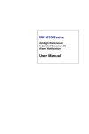
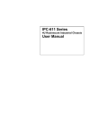
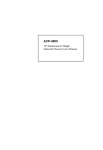
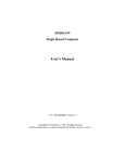
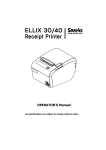
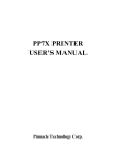
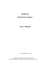
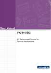
Troubleshooting
CHAPTER 5
Troubleshooting
This chapter provides you a few useful tips to quickly get your ROBO-679
running with no failure. As basic hardware installation has been addressed in
Chapter 3, this chapter will basically focus on system integration issues, in terms
of backplane setup, BIOS setting, and OS diagnostics.
5-1 Backplane Setup
Backplane
ROBO-679 is a full-sized SBC, and therefore is able to run on any PICMG
backplane, active or passive.
ATX power
ROBO-679 is designed to support ATX powering. Please refer to the following
instruction to apply ATX power on your ROBO-679 and backplane.
Demonstration model: Backplane - PBP-14P4 / ROBO-679
Step1: Remove the jumper on pin3 and pin4 of CN4 ATX P/S CONTROL
CONNECTOR, 4-pin) connector (see the Figure below). CN4 connector
is on the lower-left side of the CN7 (ATX POWER CONNECTOR) on the
backplane.
ROBO-679 User’s Manual
5-1
Troubleshooting
Step2: Connect 20-pin power cable of the ATX POWER with the CN7 (ATX
POWER CONNECTOR, 20-pin) connector on the backplane. The CN7 is
located on the upper-right side of the backplane with white color.
Step3: Use a 4-pin power cable to connect the CN4 (ATX P/S CONTROL
CONNECTOR,4-pin) connector on the backplane.
ROBO-679 User’s Manual
5-2
Troubleshooting
Step4: Please find the J5 4-pin header on the center part of ROBO-679 in white
color. You will also see a mark with “J5” at the right top corner of J5
header. Connect the 4-pin power control cable with this J5 header.
Step5: Connect TOGGLE SWITCH with J6 connector on ROBO-679. J6 connector
(2-pin) is located just on the right side of JP3 jumper of ROBO-679.
ROBO-679 User’s Manual
5-3
Troubleshooting
Step6: The figure below is the TOGGLE SWITCH, which is used to switch the
ATX Power on/off for SBC. Usually the TOGGLE SWITCH is located on
the chassis front panel. By pressing the switch button once, the power
will be on, and press again to turn it off.
Q : In addition to the above description, is there anything to do to finish up
an ATX system ??
A : Yes. ROBO-679 needs to be configured to support ATX function for the
above cabling. Please move jumper JP3 to 3-5 short and 4-6 short (support ATX
function).
Q : How can I build up an AT system using ATX power supply
A : Do not forget to move JP3 of ROBO-679 back to 1-3 short and 2-4 short
(support AT function).
If the ATX power supply has a switch, such as ORION-300ATX, leave the
jumper of backplane connector (CN4) in step 1 and use the power supply switch
as the system power on switch.
In all cases, users may apply a 2-pin AT (on/off) switch over pin-3 and pin-4 of
the backplane connector (CN4) in step 1. However, power supply switch needs
to be moved to “on”, if there is one.
ROBO-679 User’s Manual
5-4
Troubleshooting
5-2 Onboard Hardware Installation
Q: How do I connect my keyboard and mouse ??
A: Users may always adopt PS/2 keyboard and mouse over the PS/2 interface
(through Y-cable), J18, on ROBO-679.
However, it is also fine to adopt a standard keyboard over the standard
keyboard connector on backplane, if provided. In this way, users need to adopt
a 5-pin keyboard connection cable to line-up, external keyboard interface, J22 on
ROBO-679 with the 5-pin keyboard connector on backplane.
Q: OK. I have finished up hardware installation, but I got nothing when I
power on the system. Why ??
A: There are thousands of different reasons to produce this power on failure.
1.
2.
3.
Check ROBO-679 jumper JP3. For AT power supply or ATX power supply
used for AT system, JP3 needs to be at 1-3 and 2-4. Otherwise, it needs to be
at 3-5 and 4-6. Incorrect power setting will not allow you to power on the
system.
Double check if every connector is attached with the correct cable.
If you have changed processor with different system clock, please move JP2
(CMOS clear Jumper) to 2-3, power on the system to clear CMOS, power off
the system, move JP2 back to 1-2, and power on again.
Q: I power on the system, but the CPU speed is not correct. Why ??
A: This applies to Engineering Sample processor ONLY. If you have ever
loaded the BIOS optimal default, thank you for doing so. However, this will
force the BIOS to pick up the default CPU core/bus ratio as well. It needs to be
emphasized again that ROBO-679 does not have switch or jumper to configure
CPU core/bus ratio. This is done through BIOS setting. Please check in the
“Frequency/Voltage Control” section of Chapter 4 (4-11) to adjust this core/bus
ratio.
Q : I connect two IDE devices over one IDE flat cable, but the system either
does not start or hangs from time to time. Why ??
A : Make sure that you have configured the two IDE devices as master and slave,
respectively.
ROBO-679 User’s Manual
5-5
Troubleshooting
Q : I am using an ATA-66 hard drive, how can I know that ATA-66 function is
started ??
A : You need to use the 80-pin ATA-66 IDE flat cable to have this function ready.
During POST, you can see ATA-66 message while hard drive is being detected.
5-3 BIOS Setting
It is assumed that users have correctly adopted modules and connected all the
device cables required before turning on AT power. CPU, CPU fan, CPU fan
power cable, 168-pin SDRAM, keyboard, mouse, floppy drive, IDE hard disk,
printer, VGA connector, device power cables, ATX accessories or P8/P9 power
cable are good examples that deserve attention. With no assurance of properly
and correctly accommodating these modules and devices, it is very possible to
encounter system failures that result in malfunction of any device.
To make sure that you have a successful start with ROBO-679, it is
recommended, when going with the boot-up sequence, to hit “DEL” key and
enter the BIOS setup menu to tune up a stable BIOS configuration so that you
can wake up your system far well.
Loading the default optimal setting
When prompted with the main setup menu, please scroll down to “Load
Optimal Defaults”, press “Enter” and “Y” to load in default optimal BIOS
setup. This will force your BIOS setting back to the initial factory configuration.
It is recommended to do this so that you can be sure that system is running with
the BIOS setting that Portwell has highly endorsed. As a matter of fact, users
can load in the default BIOS setting any time system appears to be unstable in
boot up sequence.
Auto Detect Hard Disks
In the BIOS => Standard CMOS setup menu, pick up any
Primary/Secondary Master/Slave IDE ports, and by press “Enter”.
said IDE port and its access mode to “Auto”. This will force
automatically pick up the IDE devices that are being connected
system is booted.
one from
Setup the
system to
each time
Improper disable operation
There are too many occasions where users disable, in BIOS setup, a certain
device/feature in one application, but do not enable it before manipulating with
another application where the disabled device is needed. Certainly, users fail to
detect this device/feature and end up with system failure.
ROBO-679 User’s Manual
5-6
Troubleshooting
Please check in the BIOS setting that the devices or ports that you need are not
disabled. These include the floppy drive, COM1/COM2 ports, parallel port,
USB ports, external cache, on-board VGA and Ethernet.
It is also very common that users would like to disable a certain device/port to
release IRQ resource. A few good examples are
disable COM1 serial port to release IRQ #4
disable COM2 serial port to release IRQ #3
disable parallel port to release IRQ #7
disable PS/2 mouse to release IRQ #12,
…, etc.
A quick review of the basic IRQ mapping is given below for your reference.
IRQ#
IRQ #0
IRQ #1
IRQ #2
IRQ #3
IRQ #4
IRQ #5
IRQ #6
IRQ #7
IRQ #8
IRQ #9
IRQ #10
IRQ #11
IRQ #12
IRQ #13
IRQ #14
IRQ #15
Description
System Counter
Keyboard
Programmed Controller
COM2
COM1
Nothing
Floppy Disk Controller
Printer Port (Parallel Port)
CMOS Clock
Nothing
USB interface
Nothing
PS/2 mouse
Data Processor
Primary IDE Controller
Secondary IDE Controller
It is then very easy to find out which IRQ resource is ready for additional
peripherals. If IRQ resource is not enough, please disable some devices listed
above to release more.
5-4 OS Diagnostics
What will be presented here is a brief guide to properly house-in the driver for
any Microsoft Windows-95/98/NT device. For other operating systems, please
refer to OS manual/guidebook.
ROBO-679 User’s Manual
5-7
Troubleshooting
Booting
Users may find quite a lot that Windows-95/98 hangs in loading sequence.
Windows logo stays with no progress, or simply no display is given. Please
restart your system and hit “F5” when loading the Windows system and enter
“Safe mode”. Users will always be allowed to enter “Safe mode” with success to
remove devices that are not properly running or installed. Please proceed to do
so and restart your Windows. Removed devices will be automatically detected
again and drivers will be loaded in if drivers have been copied in the system
database, or you will be asked to provide driver source for installation.
For Windows-NT 4.0 users, it is always not recommended to change your
hardware configuration after your first installation. However, if such a change
is needed, please note that sometimes Windows-NT 4.0 will stop loading and
prompt you with a whole page of error messages. Please note that reinstallation
of this NT hard disk is inevitable. You have to backup your data stored in this
hard disk because it is almost impossible to switch back this system unless
booting up with another hard disk. If this NT hard disk is installed with FAT16
disk format, please boot up your system with any Windows OS. You will then
be able to see this NT hard disk and retrieve any data you have interest in.
However, if this NT hard disk is installed with NTFS disk format, there is only
NTFS that allows you to retrieve this NT hard disk again.
Display setup
By default, any Windows OS starts with 640 x 480 by 16 colors display. Please
load in the display driver provided in ROBO-679 product CDROM to maximize
the VGA performance. If you are using a monitor that Windows cannot identify,
you will also need to set, in the display setup menu, a system monitor to
correctly retrieve display output. For Windows-NT 4.0 users, as ROBO-679
provides Direct AGP on-board display feature, Service Pack 4.0 or above is
required to activate this display feature.
Network setup
Windows-95/98 users.
1.
2.
3.
4.
5.
Please apply an ISA/PCI network card over ISA/PCI slot.
Start Windows-95/98 and let Window-95/98 automatically detect your
network adapter.
Provide the driver and complete installation.
Restart your windows system is required.
After you come back to windows, please go to Control Panel -> System ->
Device Manager and see if your network adapter has been installed
properly. A warning sign will be prompted if the network adaptor is not
properly installed.
ROBO-679 User’s Manual
5-8
Troubleshooting
6.
7.
Please remove this network device from system setup menu and restart
windows to re-detect your network adapter again.
After you are sure that hardware installation is completed, please go to
Control Panel -> Network to set up your networking configuration. This
includes DNS, IP, Gateway. Appropriate protocols are required to carry
your networking activities. Please refer to your system administrator for
additional assistance.
Windows-NT 4.0 users.
1.
2.
3.
4.
5.
6.
7.
Please install your network adapter manually in Control Panel -> Network
-> Adapter. Drivers are required at this stage.
Proceed “Binding” after you load in the driver.
Change to Protocol label and load in the protocols that you have interest
(generally, TCP/IP). Configuring IP, gateway and DNS is required for
TCP/IP protocol.
Proceed again “Binding” after you complete the protocol loading.
Restart your system.
There is also situation that your installed network adapter is not working
anymore for you, or old network driver stays in the system after you
change your network card. Please remove then all the network adapters
and protocols from network setup menu and redo the loading of driver and
protocols again.
Network setup within Windows-NT 4.0 is not as easy as within Windows95/98. Special familiarity and care are required to come out with a
successful installation.
Note
Please visit our technical Web site at
http://www.portwell.com.tw
for additional technical information that is not covered in this manual.
ROBO-679 User’s Manual
5-9