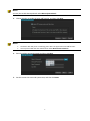
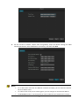
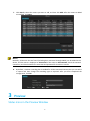
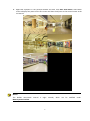
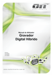
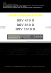
1
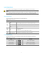
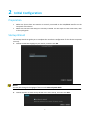
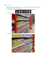
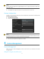
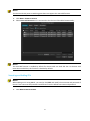
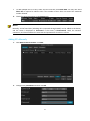
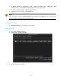
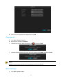
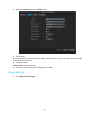
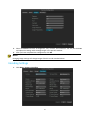
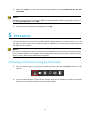
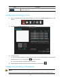
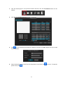
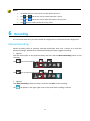
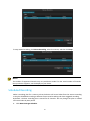
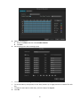
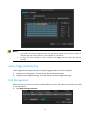
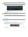
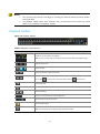
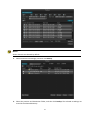
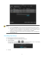
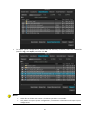
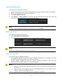
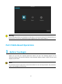
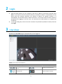
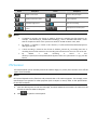
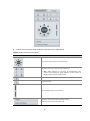
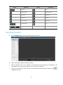
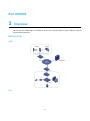
Contents Preface·············································································································· 1 Part I Local Operations····························································································1 1 Before You Begin································································································ 1 Login····················································································································1 Local Operations······································································································2 2 Initial Configuration·····························································································3 Preparation············································································································3 Startup Wizard········································································································ 3 3 Preview··········································································································· 7 Status Icons in the Preview Window···············································································7 Preview Pane Toolbar································································································7 Shortcut Menu in Preview Window················································································ 8 Example of Auto-Switch Operation················································································ 8 Digital Zoom········································································································· 10 Preview Configuration······························································································11 4 Camera Management························································································· 11 Camera Management······························································································ 11 Basic Settings········································································································ 17 Image Settings······································································································· 18 Encoding Settings··································································································· 19 5 PTZ Control····································································································· 20 Controlling a PTZ Camera Using the PTZ Toolbar······························································· 20 Configuring and Calling a Preset·················································································· 22 Configuring and Calling a Patrol Route··········································································· 23 6 Recording······································································································· 24 Manual Recording···································································································24 Scheduled Recording······························································································· 25 Alarm-Triggered Recording························································································ 27 Disk Management···································································································27 7 Playback········································································································· 28 Instant Playback····································································································· 28 Playback·············································································································· 29 Playback Toolbar···································································································· 31 8 Backup···········································································································32 Recording Backup··································································································· 32 Recording Clips Backup·····························································································34 9 Alarm············································································································ 36 Alarm Input·········································································································· 36 Alarm Output········································································································ 38 Motion Detection··································································································· 39 Tampering Detection······························································································· 41 Exception·············································································································43 1 Alarm-Triggered Actions··························································································· 44 10 Network Configuration······················································································ 45 Basic Configuration································································································· 45 PPPoE················································································································· 46 DDNS··················································································································46 UPnP·················································································································· 47 Email·················································································································· 48 11 System Configuration························································································48 Basic Configuration································································································· 48 Time Configuration································································································· 49 DST Configuration···································································································50 Preview Configuration······························································································50 View Configuration································································································· 51 Serial Port Configuration··························································································· 53 User Configuration··································································································53 12 System Maintenance························································································ 55 System Information·································································································55 Log Query············································································································ 55 Import/Export·······································································································56 System Restoration································································································· 59 Auto-Maintain······································································································· 59 System Upgrade·····································································································59 13 Shutdown······································································································61 Part II Web-Based Operations················································································· 62 1 Before You Begin·······························································································62 2 Login············································································································· 63 3 Live View········································································································ 63 PTZ Control···········································································································64 Image Settings······································································································· 66 4 Playback········································································································· 66 Recording Playback································································································· 67 Recording Download······························································································· 68 5 Configuration···································································································69 Part III DDNS······································································································ 70 1 Overview········································································································ 70 Networking·········································································································· 70 2 Access Through the App······················································································ 71 How to get the App································································································ 71 Configuration········································································································ 72 3 Access Through the Browser·················································································73 Registration·········································································································· 73 Log In················································································································· 73 Configuration········································································································ 75 2 Preface This manual is a guide to operating an NVR device (referred to as device in this manual) locally or through the Web interface. The figures in this manual are only for illustration purpose. The display may vary with device model. Please see your device for the actual display. In this manual, the terms IP camera and IPC refer to the same thing – network camera, which requires a connection to the network. The content of this manual is furnished for informational use only, is subject to change without notice, and should not be construed as a commitment. We assume no responsibility or liability for any errors or inaccuracies that may appear in the book. Part I Local Operations 1 Before You Begin Make sure you have permission for the operations you want to perform. For more details, see User Configuration. The figures in this manual are for illustration purpose only because difference exists between different models. Please see the actual display on your device. The parameters that are grayed out cannot be modified. For the actual parameters and parameter values, see the display on your device. Login NOTE! 1. 2. Use the default username “admin” and password “123456” when you log in to the device the first time. The parameters that are grayed out cannot be modified. For the actual parameters and parameter values, see the display on your device. Permissions are required for operations in the system. For more details about permission configuration, see User Configuration. Right-click anywhere in the preview window and then choose Menu. The login dialog box is displayed. Enter the correct username and password, and then click Login. To log in without entering a password next time, click Menu>System>Basic, and then clear the check box for Enable Password. 1 Local Operations You can refer to Initial Configuration and complete a quick configuration in the local GUI. NOTE! Unless otherwise specified, all operations described in this manual are performed by a right-handed user. For descriptions about how to operate the device using a mouse, see Mouse Operations. Mouse Operations This manual describes mouse operations for a right-handed user. Table 1-1 Mouse Operations Name Action Click Left button Description Select or confirm an item. Select to edit digits, symbols, upper-case or lower-case letters in a field. Double-click Enter or exit full screen mode in preview state. Drag Draw or move a rectangle on the screen, for example, when setting a privacy mask area. Show the shortcut menu. Right button Click Exit digital zoom. Exit the current window when Cancel or Exit is displayed. Wheel Rotate forward/backward Scroll up/down in a drop-down list, on a tab, or in a window. Front Panel Buttons The front panel buttons may vary with device model. Please see the buttons on your device. Table 1-2 Front Panel Lights Name Icon Description Power indicator light Power is supplied if lighted Net indicator light Network is connected if lighted. HDD indicator light HDD is on working state if lighted. 2 2 Initial Configuration Preparation Make sure that at least one monitor is correctly connected to the VGA/HDMI interface on the rear panel of the device. Make sure that the hard disk(s) are correctly installed. For the steps to install a hard disk, refer to the quick guide. Startup Wizard The startup wizard can guide you to complete the most basic configuration for the device to operate correctly. 1. Choose the default language of your device, and then click OK. NOTE! You may also change the language of device under Menu>System>Basic. 2. Choose whether to show startup wizard at the next startup, and then click Next. 3 NOTE! You may also enable Startup Wizard under Menu>System>Basic. 3. Choose whether to enable the auto-add function, and then click Next. NOTE! The device with PoE ports or switching ports does not support the auto-add function. You may also enable the auto-add function under Menu>Camera>Camera. 4. Enter the admin password 123456 and then click Next. 5. Set the correct time zone and system time, and then click Next. 4 6. Set the correct IP address, subnet mask and gateway. Keep the default settings for other network parameters unless modification is necessary. And then click Next. NOTE! For a device with more than one Network Interface Card (NIC), you can select the desired NIC and a default route. For a device with a PoE port or switching ports, you can configure an internal IPv4 address. The IP Camera window is not displayed if you have enabled the auto-add function in step 2. 5 7. Click Search, select the camera you want to add, and then click Add. After the camera is added successfully, click Next. NOTE! Normally, all the IPCs that are found (including IPCs connected through ONVIF) can be added to the device, and the status is displayed as Connected. If the status is Disconnected, check the network connection, and check whether the username and password for the IPC are correct. 8. 3 By default, a 24-hour recording plan is enabled for all the connected cameras, but you can select a camera and then change the recording type as required. After you have completed the configuration, click OK. Preview Status Icons in the Preview Window 6 The following icons indicate recording status and alarm status in the preview window. Table 3-1 Preview Icons Icon Name Description Alarm This icon appears when a motion detection alarm or a tampering alarm is reported. Recording This icon appears when manual recording is in progress. Preview Pane Toolbar A preview pane toolbar appears when you click a pane in preview status. You can use a preview pane toolbar to operate the corresponding pane. Figure 3-2 Preview Pane Toolbar Table 3-2 Pane Toolbar Buttons Button / Button Name Description PTZ Control Click this button to display the PTZ control panel for a PTZ camera in preview status. Manual Recording Click button click Instant Playback to start recording live video in the current pane toolbar, or to stop manual recording Click this button to play the video recorded within five minutes. Digital Zoom Click this button to increase the size of a certain part of an image in the current pane. Image Config Click this button to configure the image parameters in the current pane. Exit Click this button to exit the toolbar in the current pane. Shortcut Menu in Preview Window The following menu appears when you right-click anywhere in the preview window. The table below describes the menu functions. Table 3-3 Preview Operations Menu Name Description 7 Screenshot Previous Screen Next Screen Switch to the previous or next screen. Single Screen Switch the display by selecting the desired camera fromthe menu. Multi-Screen Change to the desired screen layout by selecting from the menu. Corridor Used to view videos indifferent screen layouts: 3, 5 and 7 screens. Start Auto-Switch Stop Auto-Switch Start/stop auto-switching one or multiple panes in preview status. Playback Start playback. Menu Display the main menu. Example of Auto-Switch Operation Auto-switch requires you to configure the screen layout, panes, the corresponding cameras, and the auto-switch interval. This example describes how to configure auto-switch for five cameras based on a 4-pane screen layout. 1. Right-click anywhere in the preview window, and then click Multi-Screen>4 Screens. Four screens are displayed. NOTE! Depending on the model of your device, the number of screens that can be displayed may vary. 8 2. Right-click anywhere in the preview window and then click Start Auto-Switch. Auto-switch starts to display four panes on the first screen and then the 9*pane on the second screen at the set interval. NOTE! The default auto-switch Menu>System>Preview. interval is eight 9 seconds, which can be modified under Digital Zoom Digital zoom allows you to increase the size of a certain part of an image in a pane of the preview window to get more details of the selected part. 1. Click the desired pane in the preview window and then click the Digital Zoom button. 2. Use the mouse to set an area. 3. Release the mouse to increase the size. 10 NOTE! You can restore the original size by right-clicking the area. To apply this function to other areas, repeat steps 2 and 3. 4. To exit digital zoom, right-click anywhere in the preview window in normal size. Preview Configuration Normally, you can preview live video after you have completed the startup wizard. To modify preview parameters, follow these steps. 1. Click Menu>System>Preview. 2. Configure preview parameters. NOTE! Depending on the model of your device, the supported output interfaces and the number of screens that can be displayed may vary. See your device for the actual display. 3. 4 After you have completed the configuration, click OK. Camera Management Camera Management Before you start IP camera management, make sure that the IPCs are connected to the device through network. Adding IPCs Using the Auto-Add Function 11 NOTE! The device with PoE ports or switching ports does not support the auto-add function. 1. 2. Click Menu> Camera> Camera. Select Auto-Add IP Camera. IPCs connected to the device will be added automatically. NOTE! The auto-add function is enabled by default for devices with one hard disk slot. For devices with more than one disk slot, this function is disabled by default. Searching and Adding IPCs NOTE! When adding an IPC using ONVIF, you need to click Edit and modify the username and password of the IPC if the username and password are different from the default username and password. 1. Click Menu>Camera>Camera. 12 2. 3. Click Search to perform a quick search. To make a quick search again, click Quick Search. The device searches for IPCs on the network automatically. To search a specified network segment, click Search Segment. Perform the following operations as needed. To add one IPC, select the IPC and then click Add. 13 4. To add multiple IPCs at a time, select the IPCs and then click Batch Add. You may also select Select All as required to add the IPCs if the number of IPCs does not exceed the maximum number allowed. Check the connection status on the Camera tab. NOTE! Normally, all the found IPCs (including IPCs connected through ONVIF) can be added to the device, and the status is displayed as Connected. If the status is Disconnected, check the network connection, and check whether the username and password for the IPC are correct. Adding IPCs Manually 1. Click Menu>Camera>Camera. Click Add. 2. Configure the parameters and then click OK. 14 3. Check the connection status on the Camera tab. Adding IPCs Using the Plug-and-Play Function NOTE! The Plug-and-Play function is available only for the device with PoE ports or switching ports. The Camera corresponding to a PoE port or a switching port cannot be deleted. 1. Click Menu> Camera> Camera. 2. Select the desired camera and then click Edit. 15 3. To add the camera in Plug-and-Play mode, connect the camera to an independent 100M Ethernet NIC or to an independent 100M Ethernet NIC that supports PoE. To add the camera manually, modify the parameters. Check the connection status on the Camera tab. NOTE! For a device with a PoE port, Incorrect Power will be displayed in the Status column if the power of an online IPC is lower or higher than the rated power. Advanced Settings 1. Advanced Settings is not available for the present. Editing an IPC 1. 2. Click Menu> Camera> Camera. Select the IPC and then click Edit. 3. Edit the settings as required. 16 4. After you have completed the configuration, click OK. Deleting an IPC 1. 2. Click Menu> Camera> Camera. Select the IPC and then click Delete. To delete one camera, select the camera, click To delete multiple cameras at a time, select the cameras, click Delete, and then click OK. and then click OK. NOTE! Cameras corresponding to PoE ports or switching ports cannot be deleted. Basic Settings 1. Click Menu> Camera >Basic. 17 2. Select the Camera and set the Camera name. 3. Set the OSD. You may set the date and time formats, display time and name on the screen. You may also click Set to set the position precisely. 4. Set privacy mask. Privacy mask is reserved function. 5. After you have completed the configuration, click OK. Image Settings 1. Click Menu>Camera>Image. 18 2. 3. Select the Camera and then set brightness, hue, contrast, and saturation. You may also click Set and adjust the settings while viewing images in the preview window. After you have completed the configuration, click OK. NOTE! Changing image settings will change images of both live and recorded videos. Encoding Settings 1. Click Menu> Camera >Encoding. 19 2. Select the Camera and then set the encoding parameters, including Resolution,Bit rate and Frame Rate. NOTE! Encoding types include Constant Bit Rate (CBR) and Variable Bit Rate (VBR). Image quality can be set only when Encoding Type is set to VBR. 3. 5 After you have completed the configuration, click OK. PTZ Control PTZ control allows you to control the rotation speed, viewing direction, iris, focus and turn on or off the wiper of a PTZ camera from a remote location. In addition, you can set preset positions (presets for short) for a PTZ camera. NOTE! PTZ control is applicable to the PTZ camera only and depends on the functions and protocols that the PTZ camera supports. For example, some manufacturers use presets for other purposes (such as wiper or menu). Refer to the specifications for details. Controlling a PTZ Camera Using the PTZ Toolbar 1. Click the desired pane in the preview window and then click the PTZ Control button on the toolbar. 2. The PTZ toolbar appears. Control the PTZ camera using the PTZ toolbar as required. For details about how to use the PTZ toolbar, see PTZ Toolbar Buttons. 20 Table 5-1 PTZ Toolbar Buttons Button Description Control the rotation direction of the PTZ camera or stop rotation. Adjust zoom. Adjust focus. Adjust iris. Control the rotation speed. 1 means the slowest speed, and 9 means the fastest speed. Click to enter the PTZ management. Turn on/off the light Turn on/off the wiper Preset button. Save a preset, which means setting the current status (including position) of a PTZ camera as a preset. Call a preset, so that the PTZ camera goes to the preset position. Note: Before you select a preset number, check whether a preset has been configured for this preset number. The new preset will replace the current oneafter you click the save button. Patrol route button. 21 Button Description Start a patrol route. Stop a patrol route. Configuring and Calling a Preset 1. Click the desired pane in the preview window and then click thePTZ Control button on the toolbar. 2. Click Set. The PTZ Management window is displayed. 3. Configure presets. a. Use the direction buttons to rotate the PTZ camera to the desired position, select a preset number that is not in use, and then click to save the preset. b. To add more presets, repeat the above operations. 4. Select the desired preset number from the drop-down list and then click . Configuring and Calling a Patrol Route NOTE! Each PTZ camera allows up to four patrol routes, and each patrol route allows up to eight presets. 22 1. Click the desired pane in the preview window and then click the PTZ Control button on the toolbar. 2. Click Set. The PTZ Management window is displayed. 3. Click , set the duration and speed as required, and then click OK. Repeat this step to add more key points. 4. Select the desired patrol route from the drop-down list and then click patrol route, click . 23 to start it. To stop the NOTE! 6 The default duration is 10 seconds, and the default speed is 5. The and buttons are used to modify and delete a preset. The and buttons are used to adjust the sequence of key points. The button is used to delete all the key points. Recording You can record video after you have finished the configuration as described inInitial Configuration. Manual Recording Manual recording refers to manually recording audio/video data from a camera to a hard disk. Manual recording is different from scheduled recording and alarm-triggered recording. Option 1 Click the desired pane in the preview window, and then click the Manual Recording button to start recording. Click icon to start recording, and Click icon to stop recording, and turns to turns to . . Option 2 Click Menu>Recording, select the camera, and then click Start to start recording. The icon appears in the upper right corner of the pane when recording is started. 24 To stop manual recording, click Menu>Recording, select the camera, and then click Stop. NOTE! The number of supported channels may vary with device model. For the actual number of channels that your device supports, see the display on your device. Scheduled Recording Make a recording plan for a camera so that the device will record video from the camera according to the plan.Scheduled recording is different from manual recording and alarm-triggered recording. By default a 24-hour recording plan is started for all channels. You may change the plan as needed and record video by time period. 1. Click Menu>Storage>Schedule. 25 2. Make a recording plan. a. Select the camera and then select Enable Schedule. b. Click Edit. 3. Set recording times and recording type(s). 4. To record video all day long, select All Day and then select a type. To record video by time period, set the time periods. Up to eight periods are allowed for each day. To apply the same plan to other days, select the day(s) for Copy To. Click OK. 26 NOTE! The number of channels supported may vary with device model. For the actual number of channels that your device supports, see the display on your device. To apply the same settings to other channels, click Copy and then select the desired channels. Alarm-Triggered Recording Alarm-triggered recording means that recording is triggered when an alarm is reported. 1. Configure a recording plan. For more details, see Scheduled Recording. 2. Configure alarm-triggered storage. For more details, see Alarm-Triggered Storage. Disk Management Make sure that the disks are correctly installed before you start. Only admin can format a hard disk or set disk property. 1. Click Menu>Storage>Hard Disk. 27 NOTE! The Hard Disk tab displays disk information, including total capacity, free capacity, and disk status. 2. Set disk property. a. b. c. Select the disk you want to set. Select the desired option from the Property drop-down list. Click Set. NOTE! 7 The device allows you to format a hard disk after installing it. Format a disk with caution because it will delete all the data stored on the hard disk. Playback Instant Playback Instant playback means the playback of video recorded within five minutes. Instant playback is convenient when you have detected an exception during live view. Before you use this function, check that a recording exists for the past five minutes. 1. Click the desired pane in the preview window and then click the Instant Playback button. 2. Use the slider to control the progress, and click the buttons to pause or stop playback as required. 28 Playback Playback is used to play video stored on a hard disk of the device. Before you use this function, check that a recording exists. 1. Click Menu>Playback or right-click anywhere in the preview window and then click Playback. 2. Query a recording. a. Select the desired camera. The first camera selected is the main camera, and it is in yellow font. b. Select the date from the calendar. The selected date is highlighted with yellow frames. 29 NOTE! A date with a green background color has a recording. A date with no background color has no recording. During synchronous playback for multiple cameras, the calendar shows recording status for the main camera. 3. Click the Play button or double-click the date to start playback. By default the device starts from the first recording of the selected day. You may move the slider to control the progress. 30 NOTE! You can also play back the recordings by selecting the desired channel and then doubleclicking the date. The playback toolbar offers other functions such as forward by frame, speed up, speed down. For more details, see Playback Toolbar. Playback Toolbar Figure 7-2 Playback Toolbar Table 7-2 Playback Toolbar Buttons Button Description Display the current position of playback. Note: You can move the slider to change the start time from which the playback begins. Playback progress bar. / / / Play/pause/stop Rewind 30 seconds, forward 30 seconds. Slow down or accelerate the playback. / You can click to restore the normal speed after clicking Forward by frame Digital zoom / / Start/stop clipping. Decrease or increase the size of the progress bar. Adjust volume for the selected pane. Exit the playback page. Play in full screen mode. Note: You can exit full screen mode by right-clicking the mouse. 31 , and vice versa. 8 Backup Recording Backup Backup, also known as recording backup, refers to the process of querying video stored on a hard disk of the device and then saving the recording to a USB drive as a file. The following conditions must be met for backup: The USB drive has been formatted into a FAT32 or NTFS file system and correctly plugged into the device. You have local playback permission for the corresponding camera. A recording is stored on the hard disk. NOTE! 1. Up to 80 records can be displayed on one page. If more than 80 records are retrieved, narrow down the search range and query again, or click Next to view records page by page. By default a recording is backed up as a *.mp4 file. Click Menu>Backup. NOTE! All the channels are selected by default. 2. Select the desired channel(s), set the time range, select the recording type, and then click Query. 32 NOTE! All the channels are selected by default. 3. Select the desired recording(s) and then click Backup. 4. Select the partition and destination folder, and then click Backup. The selected recordings are stored in the selected directory. 33 NOTE! You may click New Folder to create a new folder and then double-click the folder to select it. After backup is started, the progress bar shows “Exporting X/Y” to indicate the progress. The X indicates the current recording that is being backed up, and the Y indicates the total number of recordings to be backed up. To cancel the operation, click Cancel. A backup file is named in this format: camera name-recording start time. For example, Ch120141020192835.mp4. Recording Clips Backup You may also backup recording clips using USB devices. 1. Enter Playback interface. For detailed steps, see Playback. 2. Clip the recordings. During playback, use buttons and in the playback toolbar to start or stop clipping recordings. After your clipping, a system prompt will be displayed. 3. Click OK. 34 4. Select the desired recordings clips and then click Backup. 5. Select the USB partition and then click Backup. 35 NOTE! 9 After backup is started, the progress bar shows “Exporting X/Y” to indicate the progress. The X indicates the current recording that is being backed up, and the Y indicates the total number of recordings to be backed up. To cancel the operation, click Cancel. A backup file is named in this format: camera name-recording start time. For example, Ch120141020192835.mp4. Alarm Alarm Input 1. 2. Click Menu>Alarm>Alarm Input. Select the desired channel, click Set, select Enable and the correct trigger mode, and then click OK. 36 NOTE! To apply the same settings to other channels, click Copy and then select the desired channels. 3. Click Trigger Action. For more details, seeAlarm-Triggered Actions. NOTE! 4. The number of channels supported may vary with device model. For the actual number of channels that your device supports, see the display on your device. The supported alarm-triggered actions may vary with device model. For the actual actions that your device supports, see the display on your device. Set an Arming Schedule. 37 a. b. c. Click Arming Schedule. Set the plan as required. After you have completed the configuration, click Apply. NOTE! Up to eight time periods are allowed for each day. Overlapping time periods are not allowed. To apply the same plan to other days, select the day(s) right to Copy To. Alarm Output 1. 2. Click Menu>Alarm>Alarm Output. Select the desired channel, click Set, select the correct trigger mode, and set the duration. 38 3. After you have completed the configuration, click OK. NOTE! To apply the same settings to other channels, click Copy and then select the desired channels. Motion Detection The motion detection alarm function requires you to set at least one detection area on the screen, the sensitivity of detection, and an Arming Schedule. After the configuration is complete, the device will report an alarm when the movement of an object inside that area(s) reaches a certain extent during the specified period(s). 1. Click Menu>Alarm>Motion Detection. 2. Select the camera and then click Enable/Disable to enable motion detection alarm. 3. Set a detection area. 39 a. Click Detection Area. b. Drag the mouse to set a detection area. c. Right-click the detection area, click Sensitivityon the pop-up menu, and then set detection sensitivity. d. Click Apply to complete the configuration. NOTE! A greater value means a higher degree of detection sensitivity. 4. Click Trigger Action. For more details, see Alarm-Triggered Actions. NOTE! 5. The number of channels supported may vary with device model. For the actual number of channels that your device supports, see the display on your device. The supported alarm-triggered actions may vary with device model. For the actual actions that your device supports, see the display on your device. Set an Arming Schedule. a. Click Arming Schedule. b. Set the plan as needed. c. After you have completed the configuration, click Apply. 40 NOTE! Up to eight time periods are allowed for each day. Overlapping time periods are not allowed. Tampering Detection The tampering detection function requires you to set a detection area on the screen, the sensitivity of detection, actions to be triggered by a tampering detection alarm, and a guard plan. After the configuration is complete, the device will report an alarm when the detection area is blocked. 1. Click Menu>Alarm>Tampering Detection. 2. Select the camera and then click Enable/Disable to enable tampering detection alarm. 41 3. Set a detection area. a. Click Detection Area. b. Drag the mouse to set a detection area. c. Right-click the detection area, click Sensitivity on the pop-up menu, and then set detection sensitivity. d. After you have completed the configuration, click Apply. NOTE! A greater value means a higher degree of detection sensitivity. 4. Click Trigger Action. For more details, see Alarm-Triggered Actions. 42 NOTE! 5. The number of channels supported may vary with device model. For the actual number of channels that your device supports, see the display on your device. The supported alarm-triggered actions may vary with device model. For the actual actions that your device supports, see the display on your device. Set an Arming Schedule. a. ClickArming Schedule. b. Set the plan as required. c. After you have completed the configuration, click Apply. NOTE! Up to eight time periods are allowed for each day. Overlapping time periods are not allowed. Exception To configure exceptions is for the purpose of handling unexpected events. 1. Click Menu>Alarm>Exception. 2. Select the exception type, select Enable. 43 3. 4. After you have completed the configuration, click Apply. Click Exit. Alarm-Triggered Actions A reported alarm can be set to trigger multiple actions, including sound (buzzer), storage (recording video when an alarm is reported), and preview pane. The supported alarm-triggered actions may vary with device model. For the actual actions that your device supports, see the display on your device. Alarm-Triggered Sound The device starts to sound the buzzer when an alarm is reported. Alarm-Triggered E-mail The device starts to e-mail the alarm messages to the user when an alarm is triggered. Alarm-Triggered Storage The device starts to record live video from the specified camera(s) when an alarm is reported. Alarm-Triggered Preset A PTZ camera goes to a preset position when an alarm is reported. 44 Alarm-Triggered Preview If alarm-triggered preview is enabled for a camera, the device plays live video from the camera in full screen when the camera reports an alarm, and then the device switches to the next screen at the set interval. An alarm icon is displayed on the screen with the live video from the camera for differentiation. Alarm-Triggered Alarm Output The device triggers the action of a third-party device by outputting an alarm. 10 Network Configuration Network configuration is required if the device operates in a network. NOTE! The default IP address for the device is 192.168.0.30. Basic Configuration 1. 2. Click Menu>Network>Basic. Set the network parameters, including IPv4 address, subnet mask, and gateway. 3. After you have completed the configuration, click OK. 45 NOTE! If a DHCP server is used on the network, you can select Enable DHCPto obtain a dynamic IP address. If your device has more than one NIC, you can select an NIC to configure and the default route. If your device has a PoE port or switching port, you can configure an internal NIC IPv4 address. PPPoE 1. Click Menu>Network>PPPoE. 2. Select PPPoE, and then enter the correct username and password provided by your ISP. The network information will be displayed under IP Info. After you have completed the configuration, click OK. 3. DDNS 1. 2. Click Menu>Network>DDNS. Select DDNS. () 46 3. 4. After you have completed the configuration, click OK. Access your NVR remotely by domain, e.g. http://www.test.hdcctvddns.com:http port . NOTE! DDNS is enabled by default. If not, Enable HDCCTVDDNS on the NVR manually. Register at www.hdcctvddns.com . Setup an unused domain name (The domain name can be any name to identify your system). Enter the registered account in the Username and Password field. Make sure the UPNP of the router has been enabled. Or you can manually open the port on the router. UPnP UPnP means Universal Plug and Play. When UPnP is enabled for Network Address Translation (NAT), device ports can be mapped automatically to the router, and computers can access the devices from outside the LAN. You must enable UPnP in the router before using this function. 1. Click Menu>Network>UPnP. 2. By default UPnP is enabled. You may select a mapping type as needed. If you select Manual, you need to set the external ports. 3. 4. Click Refresh and check whether the status in the Status column is updated. After you have completed the configuration, click OK. Email 1. 2. Click Menu>Network>Email. Configure the related parameters. 47 To enable the server authentication, enter the correct username and password. NOTE! Depending on the location of the e-mail accounts to which you want to send notification, click the checkbox to enable SSL if required by the SMTP server. 3. 11 Click Test. Test succeeds When it prompt ‘Email test successful’. If test fails, the prompt xxx is displayed. System Configuration Basic Configuration 1. 2. Click Menu>System>Basic. Configure the parameters. 48 3. After you have completed the configuration, click OK. NOTE! Only admin can configure the Enable Password parameter. If Enable Password is not selected, no password is required for login to the device. Time Configuration 1. 2. Click Menu>System>Time. Select the correct time zone and set the system time manually. You may also select Enable NTP and then set the IP address and port number of the NTP server and the update interval. 3. After you have completed the configuration, click OK. DST Configuration 1. 2. Click Menu>System>DST. Select Enable DST and then choose the correct Start &End time、DST Bias. 49 3. After you have completed the configuration, click Apply. Preview Configuration 1. 2. Click Menu>System>Preview. Configure the parameters. NOTE! Depending on your device model, the supported output interfaces and number of screens may vary. See the actual display on your device. 3. After you have completed the configuration, click OK. 50 View Configuration View configuration is used to link channels to preview panes dynamically. Click Menu>System>View. NOTE! 1. You can change the view by clicking a button in the red box. The number of panes that can be displayed may vary, depending on your device model. The two buttons in the yellow box are used to enable or disable preview for all panes. Click to select the No.1 pane on the right, and then double-click D2 on the left. Now D2 is displayed in the No.1 pane, and None is displayed in the No.2 pane. 51 2. Click to select the No.2 pane on the right, and then double-click D1 on the left. Now D1 is displayed in the No.2 pane. 3. After you have completed the configuration, click OK. 52 Serial Port Configuration Serial port settings in the device should be consistent with that of the connected serial device. Serial port configuration is required for PTZ control. 1. Click Menu>System>Serial. 2. Configure the parameters for the serial port. 3. After you have completed the configuration, click OK. User Configuration User is the entity that manages and uses the system. User role is a collection of operation permissions. When a role is assigned to a user, this user is assigned all the permissions defined for the role. There are three user types in the system: Admin: By default the super administrator of the system and has full permissions. The initial password for admin is 123456. Operator: By default an operator has basic permissions and channel permissions. Admin can modify permissions assigned to operators. Guest: By default a guest has channel permissions. Admin can modify permissions assigned to a guest. NOTE! Only admin can add, delete and modify users. 1. Click Menu>System User. 2. User configuration Add a user. a. Click Add. b. Set the username, password, user role and permissions. 53 c. After you have completed the configuration, click OK. NOTE! The system allows up to eight users including admin. Delete a User Select the desired user(s) and then click Delete. After you have completed the configuration, click OK. Modify a User d. Select the desired user and then click Modify. e. Modify the password, role and permission as needed. 54 f. After you have completed the configuration, click OK. NOTE! The user must use the new password to log in after the password is changed. 12 System Maintenance System Information View the basic information about the device for maintenance purpose. 1. Click Menu>Maintain>SystemInfo. 2. View the device information, including device model, bar code, and software version. Log Query Logs record operations performed by users and device operation status. By analyzing logs, you can keep track of device operation status and view detailed alarm information. 1. Click Menu>Maintenance>Log Query. 55 2. 3. Set query condition, including the start time and end time, main log type and subtype. Click Query. Results matching the condition are displayed. Import/Export Users who have permission to configure can back up the system. Only admin can export system configurations to a USB drive or import system configurations and databases from a USB drive. 56 Refreshing Information about a USB Drive 1. Click Menu>Maintain>Import/Export. 2. Import/Export Configurations To export system configurations, click Export. A file named *.cfg will be created in the selected folder if the export operation is successful. To export maintenance information, click Export Maintain Info. A file named *.tgz will be created in the selected folder if the export operation is successful. 57 To import system configurations, double-click the directory in the list, select the correct file (named *.cfg), click Import, and then click OK. NOTE! Delete files or folders with caution. The delete operation is irreversible. Only admin can export system configurations, maintenance information and import system configurations. 58 System Restoration The system can be restored in two ways: Restore: All settings, except network settings and user settings, will be restored to the defaults. Default: All settings will be restored to the defaults. 1. Click Menu>Maintain>Restore. 2. Click Default or Factory Default as required, and then click OK. The device will restart and restore the system according to the mode you have chosen. NOTE! Recorded videos and operation logs will not be deleted if you click Default. Auto-Maintain Only admin can perform this operation. 1. Click Menu>Maintain>Auto-Maintain. 2. Set when the system automatically restarts and deletes files as required. NOTE! Files that are deleted automatically cannot be recovered. System Upgrade There are two ways to upgrade the device: Local upgrade: upgrade the device by using an upgrade file backed up in a USB drive. For more descriptions about using a USB drive, see System Upgrade. Remote upgrade: upgrade the device by using an upgrade file added in web. For more descriptions about using a USB drive, see System Upgrade. NOTE! Maintain a normal power supply during upgrade. Use an Uninterrupted Power Supply (UPS) if necessary. Before you start a local upgrade, copy the correct upgrade file to the root directory of the USB drive. Otherwise, the upgrade will fail. The device will restart automatically after the upgrade is completed. 59 1. Local upgrade a. Click Menu>Maintain>Upgrade. b. c. 2. Click Upgrade. Select the directory containing the upgrade file in the USB drive and then click Upgrade. Remote upgrade a. Access the web page of the NVR. For more details, see “Part II Web-Based Operations” ; 60 13 b. Select Settings>Maintenance> Maintenance. c. d. Click Browse. Select the directory containing the upgrade file from the PC and then click Upgrade. Shutdown You can perform logout, restart and shutdown operations in the Shutdown window. It is recommended that you disconnect the device from the power supply if the device will not be used for a long time. You can also shut down the device by pressing the power button on the front panel for at least three seconds and then confirming the operation. 1. Click Menu>Shutdown. 2. Click the button as needed. 61 Warning: Unsaved settings will be lost if the device is shut down in an incorrect manner, for example, due to a power failure. An incorrect shutdown during an upgrade may cause startup failures. Part II Web-Based Operations 1 Before You Begin Make sure you have the required permission before you start. The following figures are for illustration purpose only because difference exists between different models. Please see the actual display on your device. NOTE! The parameters that are grayed out cannot be modified. For the actual parameters and parameter values, see the display on your device. 62 2 Login 1. 2. 3 Open the Web browser on your computer, input the IP address of the device and then press Enter. For the device with one network interface, the default IP address is 192.168.0.30. For the device with two network interfaces, the default IP address for network interface 1 is 192.168.0.30, and 192.168.1.30 for network interface 2. You need to load the latest ActiveX as prompted when logging in the first time. You need close the Web browser to complete the installation. In the login dialog box, enter the correct username and password (123456 for admin) and then click Login. Live View By default the Live Video page is displayed when you are logged in. Table 3-1 Live View Control Buttons Button / / Description Button Description Start/stop preview for all panes / Previous screen/next screen Start/stop talk / Adjust microphone volume 63 Button Description Button Description Switch screen layout Set the clarity of images Display in full screen mode Take a snapshot / Start/Stop digital zoom / Adjust volume, turn on/off sound. Start local recording / / Open/close the control panel NOTE! A snapshot is named in this format: IP address_channel ID_snapshot time.file extension. For example, 192.168.0.30_D1_20140311102123239.jpg, where 20140311102123239 means that the snapshot is taken at the system time of 10:21:23:239 on March 11th, 2014. By default, a snapshot is saved in this directory: C:\Users\username\Uware\Snap\system date (yyyy-mm-dd). A local recording is named in this format: IP address_channel ID_S recording start time E recording end time.file extension. The recording start and end times are in hh-mm-ss format. By default, a local recording is saved in this directory:C:\Users\username\Uware\Record\system date. The system date is in yyyy-mm-dd format. PTZ Control PTZ control allows you to remotely control the rotation angle, iris, zoom, focus and turn on or off the wiper of a PTZ camera. NOTE! PTZ control depends on the functions and protocols that a PTZ camera supports. For example, some manufacturers use presets for other purposes (such as wiper or menu). Refer to the specifications for the PTZ for details. 1. Click the desired pane on the live view page, and then double-click an online PTZ camera on the left side to start live video in the pane. 2. Click to open the control panel. 64 3. Control the PTZ camera using the buttons described in the table below. Table 3-2 PTZ Control Pane Description Button Description Control the rotation direction of a PTZ camera. Adjust the zoom, focus, and iris of the camera lens. Note: When adjusting iris and focus for high-definition Sony cameras that support the VISCA protocol, set the camera to MANUAL mode using the remote control. Control the light. Control the wiper. Set the rotation speed of a PTZ camera. Preset list: Choose the preset for the PTZ rotation. Patrol by Preset: Choose the patrol route. 65 Image Settings 4 1. Click the desired pane on the live view page, and then double-click an online PTZ camera on the left to start live video. 2. 3. Click to open the control panel, and then click Image. Use the sliders to set the contrast, hue, saturation and brightness of images in preview status. Set the pane scale as needed. Playback Click Playback to open the Playback page. Table 4-1 Playback Control Buttons 66 Button / / Description Button Description Play/pause Stop Rewind by frame Forward by frame Rewind 30s Forward 30s Speed down Speed up Previous period Next period Clip video/pause Save Adjust volume, turn on/off sound - - Recording Playback 1. On the Playback page, select the desired camera on the left. 2. Query recordings using the following methods. Click the desired date on the calendar. The timeline shows the status of recordings in the selected day. You can move the slider to set a start time for playback. To query by time period, enter the time in the fields below the calendar and then click to pinpoint the time. 67 NOTE! 3. Each date has a flag in the upper right corner to indicate recording status for that day. Different colors have different meanings. Green: The camera has a 24-hour recording for that day. Yellow: The camera has incomplete recording for that day (recording exists but less than 24 hours). Red: The camera has no recording for the whole day. Click Play to start playback. Recording Download Check that the camera has recorded video (recording) before you perform this operation. 1. On the Playback page, select the desired camera on the left and then click on the right of the camera. 2. Download recordings. a. Enter the start time and end time, and then click Query. Recordings during the set period are listed. b. Select the desired recording file and download mode, and then click Download. The download progress is displayed. A download list appears when you click the progress bar. 68 NOTE! By default a downloaded recording is saved to the following C:\Users\username\Uware\Download\system date (in yyyy-mm-dd format). 5 directory: Configuration Click Settings on the main page, and then click the menu on the left to configure parameters. 69 Part III DDNS 1 Overview You can use the mobile app or the Web to view live or recorded video of your residence, shop or office anytime anywhere. Networking WAN LAN 70 2 Access Through the App How to Get the App NOTE! You are recommended to download the app via Wi-Fi. You can get the free app by the following two methods: 1. Scan the QR Code to get ISS Mobile for 2. Android; Scan the QR Code to get ISS Mobile for IOS; Or you can Search and download the ISS Mobile (IOS) from the App store and the ISS Mobile (Android) from Google Play. 71 Configuration 3. Step2 4. Step3 5. Step4 Enter a name for NVR Press the QR code icon and line up the QR code on top of the NVR with the camera of your phone or tablet. OR if your device does not have a camera, manually enter the Device ID printed on the label. Choose Diamond NVR Cloud under Mode dropdown list 6. Step5 Tap 7. Tap ” Start Live View”. Congratulations! You can now view video from your cameras on your Smartphone or tablet! 72 NOTE! If you have changed the User Name, Password from the defaults, you will need to update them. Find your Device ID. The Device ID is printed on a label on the top panel of the NVR. Make sure the UPNP of the router has been enabled. 3 Access Through the Browser Registration 1. 2. Go to http://www.hdcctvddns.com/ and click Register. Complete the registration according to the instructions. Log In 1. Finish registration and click Login Now. 73 2. Enter the username and password to Login. 3. DDNS Account Register successfully. 4. Setup Network and DDNS parameters of NVR. (See more details from Network Configuration) 74 5. Click UPNP> enable UPNP>OK. Access 1. Refresh the page ‘http://www.hdcctvddns.com/usercenter.html’ and you will find the IP address of your domain. 75 2. Click the domain to go to the DVR login page in the browser, or access the device with it’s domain +web port, e.g. http://testddns.hdcctvddns.com/ 76