1
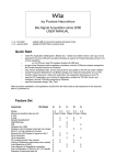
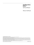
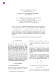
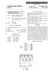
VivoSense User Manual - BioRadio Import Module VivoSense BioRadio Import Version 2.0 Vivonoetics - San Diego Office 3231 Huerfano Court, San Diego, CA, 92117-3630 Tel. (858) 876-8486, Fax. (248) 692-0980 Email: [email protected]; Web: www.vivonoetics.com VivoSense - BioRadio Import Module Cautions and disclaimer VivoSense software is not a medical diagnostic tool and is intended for research and investigational purposes only. VivoSense is not intended to be, or to replace, medical advice or review by a physician. Copyright Notice Copyright © 2011 Vivonoetics. All rights reserved. User Documentation BioRadio Import Module Page 2 of 18 VivoSense - BioRadio Import Module Table of Contents 1. Introduction ............................................................................................................. 4 1.1. VivoSense for BioRadio .................................................................................................................. 4 1.2. System Requirements ..................................................................................................................... 4 2. Importing Data ........................................................................................................ 5 2.1. .bcr File ........................................................................................................................................... 5 2.2. BioCapture ...................................................................................................................................... 8 3. Processing Data Channels ................................................................................... 10 3.1. Accelerometer Data Channels ...................................................................................................... 10 3.2. Electrocardiogram (ECG) Data Channels ..................................................................................... 10 3.3. Respiration Data Channels ........................................................................................................... 11 3.4. Electroencephalogram (EEG) Channels ....................................................................................... 12 3.5. Electromyogram (EMG) Channels ................................................................................................ 13 3.6. Pulse Oximeter Data Channels ..................................................................................................... 14 3.7. Galvanic Skin Response (GSR) Data Channels ........................................................................... 14 3.8. Spirometer Data Channels ............................................................................................................ 14 3.9. Temperature Data Channels ......................................................................................................... 15 3.10. 4. Generic Data Channels ............................................................................................................. 16 BioRadio Layouts ................................................................................................. 18 User Documentation BioRadio Import Module Page 3 of 18 VivoSense - BioRadio Import Module 1. Introduction 1.1. VivoSense for BioRadio This manual describes the use of the BioRadio import module for VivoSense software and its ability to import and analyze data collected with BioRadio 150 (Cleveland Medical Devices, Inc.) series sensor system. The BioRado import module is generally included as part of the core version of VivoSense. For more information about available data and capabilities of the BioRadio 150 series, please refer to the Cleveland Medical BioRadio 150 series user manuals. 1.2. System Requirements The BioRadio import module is an add-on module to VivoSense. In addition to VivoSense requirements, the BioRadio import module has the following system requirements: BioRadio wireless receiver – to receive data wirelessly from the BioRadio 150 series and transfer it to a PC BioRadio accessories – specific to the type of data desired (e.g respiration band, ECG electrodes, etc) BioCapture software – visualizes and records real-time data from the BioRadio 150 series User Documentation BioRadio Import Module Page 4 of 18 VivoSense - BioRadio Import Module 2. Importing Data Ambulatory physiological data from the BioRadio system is recorded through Cleveland Medical‟s BioCapture software and stored as a .bcr file on the PC. The .bcr file and BioCapture are discussed in the following two sections. 2.1. .bcr File VivoSense can import .bcr files saved from BioCapture. The BioRadio import option is available from the File -> Import Hardware File menu. Upon selecting a .bcr file, VivoSense will open the file and look for all available data channels. These channels will then be presented along with a mapping of channels that VivoSense can import in the Import Configuration Wizard. See Figure 1 Figure 1. BioRadio Import Configuration Wizard At this point, a user can select all or a subset of the channels that they would like to analyze in VivoSense. To do this, find the row of the desired channel and then click once on the Channel Type entry. A drop down box will appear with the possible options. Upon choosing the desired type, a corresponding VivoSense channel name will automatically be selected for you. SeeFigure 2 . User Documentation BioRadio Import Module Page 5 of 18 VivoSense - BioRadio Import Module Figure 2. BioRadio Import Configuration Wizard - Selecting a channel type If you would like to modify the VivoSense channel name, simply click on it and another drop down box will appear with alternative possibilities. A VivoSense channel name can only be used once. This will result in an error message after selecting the „Done‟ button if multiple BioRadio channel names have been assigned to a single VivoSense channel. VivoSense will automatically down sample BioRadio channels to the minimum appropriate sampling frequency possible for the selected channel type. Down sampling reduces unnecessary file size and noise in the data caused by over sampling a channel. For example, an accelerometer channel sampled at 256 Hz alongside an ECG channel, will be automatically down sampled to 64 Hz, while the ECG channel will remain sampled at the appropriate rate of 256 Hz. Vivosense will down sample appropriate channels in factors of 2. A 256 Hz channel will be down sampled to 128 Hz > 64 Hz >32 Hz and so on. The down sample rate can be modified by using the drop down menu in the File Import Configuration. The down sample rate can be set back to the original sample rate by selecting a down sample rate of “None”. See Figure 3. User Documentation BioRadio Import Module Page 6 of 18 VivoSense - BioRadio Import Module Figure 3. BioRadio Import Configuration Wizard - Downsample Once you have created the desired mapping of BioRadio channels to VivoSense channels, press the „Done‟ button. If this is a new configuration, you will be prompted to save your configuration for later use. This can significantly speed up subsequent imports of files with the same configurations by allowing VivoSense to automatically perform the mapping process for you. Figure 4 displays how on the second import of a file with the same channels, a configuration can be loaded that automatically selects the previously saved VivoSense channels. Figure 4. BioRadio Import Configuration Wizard – Loading a configuration User Documentation BioRadio Import Module Page 7 of 18 VivoSense - BioRadio Import Module In addition to channel mappings, the start time of the recording can also be set within the Import Configuration Wizard. Click on any number within the Start Time Box to change it to the desired value. The format is HH:mm:ss dd/MM/yyyy. Clicking on the Start Time Box‟s document icon will cause a calendar to appear that allows for quick selection of the recording date. This start time will be saved and applied along with the channel mappings when a configuration is used in later imports. 2.2. BioCapture The BioCapture software allows configuration and data recording from a single BioRadio 150 series system. A brief overview of the recording process is provided here and a more detailed explanation can be found in Cleveland Medical‟s BioCapture documentation. To set up BioCapture for a recording, first start the program and search for nearby devices. Your BioRadio 150 series unit must be turned on and close by for this to work. Once discovered, your BioRadio can be configured to record whatever physiological signals that may be attached. Users create channel configurations that include the name of the signal to be recorded as well as any scaling that should be applied before the data are saved. See Figure 5. It is important to note that the names given to the data channels at this point will be read in by VivoSense at the time of import. Using descriptive channel names is highly recommended as this will make the import process much easier. After your BioRadio 150 series device has been configured, press the record button to begin viewing and saving real-time data. After finishing your recording, press the stop button and then save the .bcr file when prompted. The data file may now be imported into VivoSense as described in section 2.1. Please note that BioRadio data may be susceptible to radio loss if the subject moves out of range. Dropped data will appear in VivoSense as blank spaces in the data plots. VivoSense will perform calculations around these losses and all VivoSense statistics and algorithms will refer only to the available data. User Documentation BioRadio Import Module Page 8 of 18 VivoSense - BioRadio Import Module Figure 5. BioCapture – BioRadio device configuration User Documentation BioRadio Import Module Page 9 of 18 VivoSense - BioRadio Import Module 3. Processing Data Channels Available data channels from BioRadio devices may be divided into 2 categories: Raw data channels from the device and derived channels – as calculated by VivoSense. The raw data channels from BioRadio are located in the Data Explorer under the “Raw” node. They include Waveforms, Measures and Information channels, as described in the following sections. All Raw channels are prefixed with BCR_. For complete information regarding the data in each of these channels, please consult the hardware documentation for the specific BioRadio unit. The core VivoSense manual contains a general description of the derived channels. Only the derived channels that are particular to the BioRadio product are described here. 3.1. Accelerometer Data Channels The BioRadio accelerometer measures acceleration along 2 axes denoted by BCR_AccX and BCR_AccY (Lateral and Longitudinal respectively). The raw data is measured in computer units (cu) with an arbitrary offset. The conversion to physical units in the derivation of Core Channels (AccX and AccY) is obtained by scaling the raw data with a constant gain provided by the manufacturer and by shifting the offset by an amount specific to the individual hardware. This calibration is done automatically upon import. See the VivoSense core manual for additional information regarding axis definitions. Raw Accelerometer Waveforms BCR_AccX Acceleration, measured along the X axis BCR_AccY Acceleration, measured along the Y axis 3.2. Electrocardiogram (ECG) Data Channels VivoSense provides the ability to import up to two ECG signals for analysis. These are denoted as BCR_ecg1 and BCR_ecg2. VivoSense will process both channels and perform QRS detection on both to generate two sets of R-wave markings. VivoSense further provides options to select one of the ECG channels as the primary source ECG for further analysis (i.e. derived measures such as RR and HR).This selection may be performed by navigating to the Properties of the RR channel and selecting either RR1 or RR2 from the Source Channel dropdown menu. If only one ECG is recorded, it will not be necessary to select the source channel. Raw Electrocardiogram Waveforms BCR_ECG1 Primary ECG raw signal User Documentation BioRadio Import Module Page 10 of 18 VivoSense - BioRadio Import Module BCR_ECG2 Secondary ECG raw signal Electrocardiogram Waveforms Ecg1 Filtered BCR_ecg1. Ecg2 Filtered BCR_ecg2. Electrocardiogram Markings Rwave1 This channel identifies the peak of the R-wave on the corresponding Ecg1 waveform. These markings are provided as a result of the QRS detection algorithm implemented in VivoSense. Rwave2 This channel identifies the peak of the R-wave on the corresponding Ecg2 waveform. These markings are provided as a result of the QRS detection algorithm implemented in VivoSense. Electrocardiogram Measures RR1 This channel represents the time interval between two consecutive R-waves in seconds as marked by Rwave1. This channel may be further used to adjust specific parameters of the QRS detection algorithm for Ecg1. RR2 This channel represents the time interval between two consecutive R-waves in seconds as marked by Rwave2. This channel may be further used to adjust specific parameters of the QRS detection algorithm for Ecg1. RR RR is a duplicate of either RR1 or RR2 depending on the selection for the „Source Channel‟ property of RR and represents the time interval between two consecutive R-waves in seconds. All subsequent derived measures, for example heart rate, heart rate trends, or heart rate variability calculations, are derived from the primary selected RR channel. A secondary Ecg signal allows the user to choose the optimum source channel based on data quality and accuracy of R-wave markings. 3.3. Respiration Data Channels VivoSense allows for the import of up to four respiratory signals within a single .bcr file. These signals can come from any combination of the following: One or two Respiratory Inductive Plethysmography (RIP) bands, User Documentation BioRadio Import Module Page 11 of 18 VivoSense - BioRadio Import Module located on either the abdomen or ribcage of the subject, and one or two Strain Gauge bands, located on either the abdomen or ribcage of the subject. All respiratory measurements in VivoSense are divided into two categories, RIP and Strain, depending on the source of the data. If both abdominal and thoracic signals are available for a particular respiratory band type, then all measurements will be derived by summing the two signals and performing the normal sequence of calculations (see Core manual). If only one signal is available for either the RIP or Strain type, then in some instances volumetric measurement may not be accurate due to contributions to the breathing cycle from two compartments (thoracic and abdominal) when only a single breathing compartment is being measured. Raw Respiration Waveforms BCR_RipRC This is the raw respiration waveform recorded from the BioRadio. Thoracic excursions are measured in nonphysical computer units. The tidal Volume waveform, Rip Vt, is derived from BCR_RipRC by summing it with BCR_RipAB (if available) and then scaling with a gain factor obtained from a calibration procedure performed automatically on import. This calibration factor is determined by scaling the estimated average peak to trough excursions to 400 ml. BCR_RipAB This is the raw respiration waveform recorded from the BioRadio. Abdominal excursions are measured in non-physical computer units. The tidal Volume waveform, Rip Vt, is derived from BCR_RipAB by summing it with BCR_RipRC (if available) and then scaling with a gain factor obtained from a calibration procedure performed automatically on import. This calibration factor is determined by scaling the estimated average peak to trough excursions to 400 ml. BCR_StrainRC This is the raw respiration waveform recorded from the BioRadio. Thoracic excursions are measured in nonphysical computer units. The tidal Volume waveform, Strain Vt, is derived from BCR_StrainRC by summing it with BCR_StrainAB (if available) and then scaling with a gain factor obtained from a calibration procedure performed automatically on import. This calibration factor is determined by scaling the estimated average peak to trough excursions to 400 ml. BCR_StrainAB This is the raw respiration waveform recorded from the BioRadio. Abdominal excursions are measured in non-physical computer units. The tidal Volume waveform, Strain Vt, is derived from BCR_StrainAB by summing it with BCR_StrainRC (if available) and then scaling with a gain factor obtained from a calibration procedure performed automatically on import. This calibration factor is determined by scaling the estimated average peak to trough excursions to 400 ml. 3.4. Electroencephalogram (EEG) Channels The BioRadio system allows for the connection of an up to eight EEG sensors. Raw Electroencephalogram Waveforms BCR_EEG1 This is the first raw EEG signal. User Documentation BioRadio Import Module Page 12 of 18 VivoSense - BioRadio Import Module BCR_EEG2 This is the second raw EEG signal. BCR_EEG3 This is the third raw EEG signal. BCR_EEG4 This is the fourth raw EEG signal. BCR_EEG5 This is the fifth raw EEG signal. BCR_EEG6 This is the sixth raw EEG signal. BCR_EEG7 This is the seventh raw EEG signal. BCR_EEG8 This is the eighth raw EEG signal. 3.5. Electromyogram (EMG) Channels The BioRadio system allows for the connection of an up to eight EMG sensors. Raw Electromyogram Waveforms BCR_EMG1 This is the first raw EMG signal. BCR_EMG2 This is the second raw EMG signal. BCR_EMG3 This is the third raw EMG signal. BCR_EMG4 This is the fourth raw EMG signal. BCR_EMG5 This is the fifth raw EMG signal. BCR_EMG6 This is the sixth raw EMG signal. User Documentation BioRadio Import Module Page 13 of 18 VivoSense - BioRadio Import Module BCR_EMG7 This is the seventh raw EMG signal. BCR_EMG8 This is the eighth raw EMG signal. 3.6. Pulse Oximeter Data Channels The BioRadio 150 system can connect to an optional Nonin pulse oximeter that calculates oxygen saturation and pulse rate. Raw Pulse Oximeter Measures BCR_SpO2 This raw measurement is calculated internally on the pulse oximeter, and provides an indication of percent oxygen saturation. BCR_PulseRate This raw measurement is calculated internally on the pulse oximeter, and provides heart rate in beats per minute. These measurements are averaged to a one second interval. 3.7. Galvanic Skin Response (GSR) Data Channels The BioRadio system allows for the connection of an optional sensor for measuring Galvanic Skin Response (GSR). Raw Galvanic Skin Response Waveforms BCR_GSR This is the raw GSR waveform recorded from the optional sensor. 3.8. Spirometer Data Channels The BioRadio system allows for the connection of an optional spirometer sensor for measuring air flow. Raw Spirometer Waveforms BCR_Spirometer This is the raw waveform recorded from the spirometer. VivoSense expects this to be in millivolts. User Documentation BioRadio Import Module Page 14 of 18 VivoSense - BioRadio Import Module Spirometer Waveforms Flow This is the filtered and calibrated air flow waveform, which was derived from the raw BCR_Spirometer waveform by applying a gain and offset, and then low pass filtering the signal. The gain is from hardware specifications. By default, the offset is set to the mean of the data. 3.9. Temperature Data Channels VivoSense allows the import of up to eight temperature waveforms from the BioRadio. Raw Temperature Waveforms BCR_Temp1 This channel provides the raw temperature waveform from an optional external temperature sensor. BCR_Temp2 This channel provides the raw temperature waveform from an optional external temperature sensor. BCR_Temp3 This channel provides the raw temperature waveform from an optional external temperature sensor. BCR_Temp4 This channel provides the raw temperature waveform from an optional external temperature sensor. BCR_Temp5 This channel provides the raw temperature waveform from an optional external temperature sensor. BCR_Temp6 This channel provides the raw temperature waveform from an optional external temperature sensor. BCR_Temp7 This channel provides the raw temperature waveform from an optional external temperature sensor. BCR_Temp8 This channel provides the raw temperature waveform from an optional external temperature sensor. Temperature Waveforms Temp1 This is the calibrated temperature in degrees Celsius. User Documentation BioRadio Import Module Page 15 of 18 VivoSense - BioRadio Import Module Temp2 This is the calibrated temperature in degrees Celsius. Temp3 This is the calibrated temperature in degrees Celsius. Temp4 This is the calibrated temperature in degrees Celsius. Temp5 This is the calibrated temperature in degrees Celsius. Temp6 This is the calibrated temperature in degrees Celsius. Temp7 This is the calibrated temperature in degrees Celsius. Temp8 This is the calibrated temperature in degrees Celsius. 3.10. Generic Data Channels VivoSense allows for the import of other raw data signals that may not yet be sold by Cleveland Medical, or are not yet fully supported. Raw Generic Waveforms BCR_Generic1 This is the raw waveform for generic signal 1. BCR_Generic2 This is the raw waveform for generic signal 2. BCR_Generic3 This is the raw waveform for generic signal 3. BCR_Generic4 This is the raw waveform for generic signal 4. BCR_Generic5 This is the raw waveform for generic signal 5. User Documentation BioRadio Import Module Page 16 of 18 VivoSense - BioRadio Import Module BCR_Generic6 This is the raw waveform for generic signal 6. BCR_Generic7 This is the raw waveform for generic signal 7. BCR_Generic8 This is the raw waveform for generic signal 8. Generic Trends Trend Generic1 This is a computed trend of the raw generic waveform BCR_Generic1. The default is comprised of the medians from five-minute windows. Trend Generic2 This is a computed trend of the raw generic waveform BCR_Generic2. The default is comprised of the medians from five-minute windows. Trend Generic3 This is a computed trend of the raw generic waveform BCR_Generic3. The default is comprised of the medians from five-minute windows. Trend Generic4 This is a computed trend of the raw generic waveform BCR_Generic4. The default is comprised of the medians from five-minute windows. Trend Generic5 This is a computed trend of the raw generic waveform BCR_Generic5. The default is comprised of the medians from five-minute windows. Trend Generic6 This is a computed trend of the raw generic waveform BCR_Generic6. The default is comprised of the medians from five-minute windows. Trend Generic7 This is a computed trend of the raw generic waveform BCR_Generic7. The default is comprised of the medians from five-minute windows. Trend Generic8 This is a computed trend of the raw generic waveform BCR_Generic8. The default is comprised of the medians from five-minute windows. User Documentation BioRadio Import Module Page 17 of 18 VivoSense - BioRadio Import Module 4. BioRadio Layouts VivoSense contains a collection of Layouts specific to the BioRadio Import module. The following layouts are provided with the BioRadio Import module. Actigraphy This is a set of Charts suitable for evaluating the motion or activity of a subject. This layout contains channels for each calibrated accelerometer axis as well as derived posture and motion measures. Breath Detection and Calibration This is a specific set of Charts designed for adjusting the breath detection settings and calibrating the Vt waveform. All of the charts necessary for the examination of changes in breath detection are available. This layout also provides easy access to the Breath channel (for adjusting breath detection settings) as well as the Insp Vol channel (for performing a fixed volume calibration). Changing the Breath Detection settings will result in changes in Rip respiratory measures and their corresponding trends. Cardiac This is a set of Charts suitable for use when evaluating cardiac information from an electrocardiogram sensor. This layout contains one filtered Ecg waveform, results of QRS detection and subsequent derived RR intervals. A trend of the heart rate is included along with accelerometer waveforms to be used for context interpretation and identification of artifact. If necessary this layout should be used for making changes to the R-wave picker settings. Respiration This is a set of Charts suitable for use when evaluating rip respiration data and contains several key respiration measures and trends. The Rip Vt waveform with breath detection markings, as well as the accelerometer waveforms are displayed to aid with context interpretation. Sleep This is a set of Charts suitable for use when evaluating sleep data and contains respiratory waveforms and measures, motion and posture data, as well as oxygen saturation data. User Documentation BioRadio Import Module Page 18 of 18