1
UM10208
Chapter 20: LPC288x I2S input module (DAI)
Rev. 01 — 5 September 2006
User manual
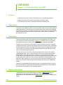
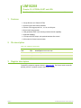
1. Features
•
•
•
•
I2S input via Digital Analog In (DAI) module
Digital values 16 to 24 bits
Streaming Analog In (SAI) module provides FIFO buffering
DMA or processor transfer
2. Description
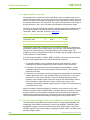
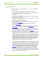
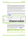
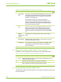
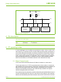
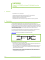
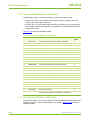
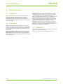
The LPC288x can input a single- or dual-channel audio stream from an Inter-IC Sound
(I2S) bus. The I2S input module is called the DAI. It can capture serial data in standard
Philips IIS format, or in right-justified 16-, 18-, 20-, or 24-bit format.
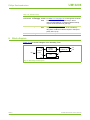
Because the ARM7 microcontroller services a variety of tasks in an interleaved fashion
that involves worst-case event-arrival considerations, a FIFO buffer called an SAI is
included to smooth the transfer of the digital values from the DAI to memory. This transfer
can be performed by the processor or by GPDMA channel(s).
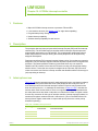
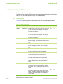
3. DAI pins
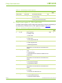
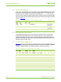
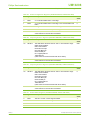
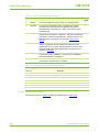
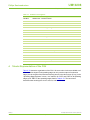
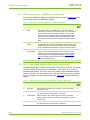
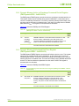
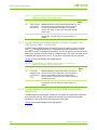
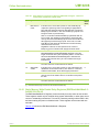
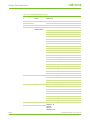
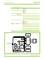
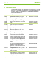
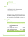
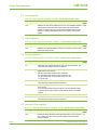
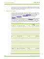
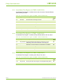
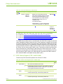
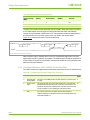
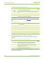
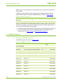
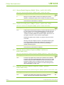
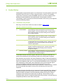
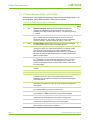
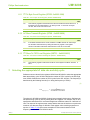
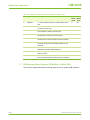
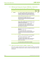
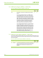
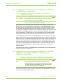
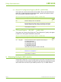
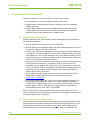
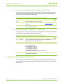
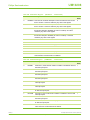
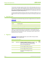
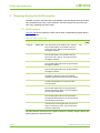
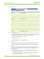
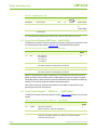
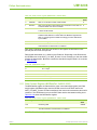
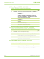
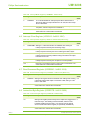
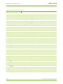
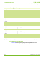
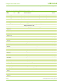
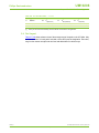
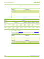
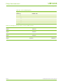
The DAI has three dedicated pins, as shown in Table 20–274.
Table 274. DAI pins
Name
Type
Description
BCKI / P3[1]
I/O
Bit clock
DATI / P3[0]
I
Data from remote device
WSI / P3[2]
I/O
Word select. This signal differentiates L data from R data.
4. DAI registers
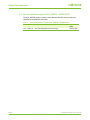
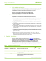
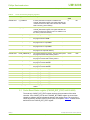
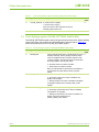
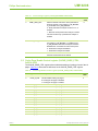
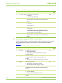
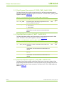
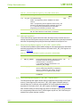
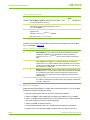
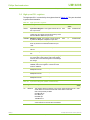
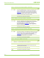
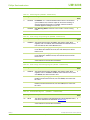
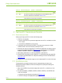
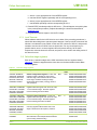
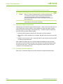
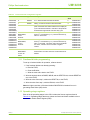
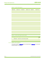
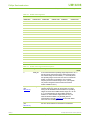
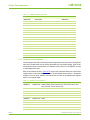
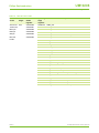
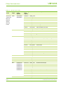
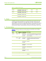
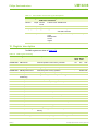
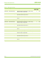
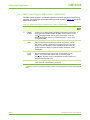
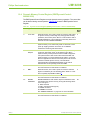
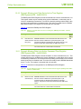
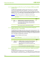
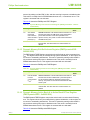
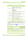
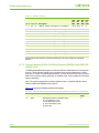
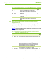
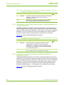
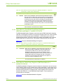
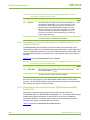
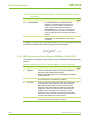
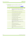
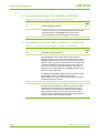
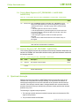
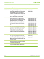
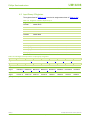
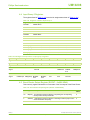
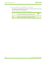
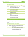
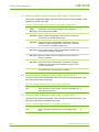
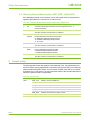
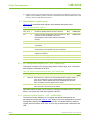
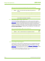
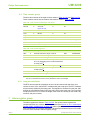
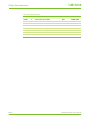
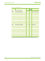
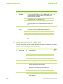
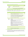
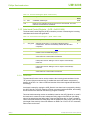
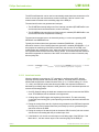
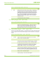
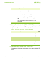
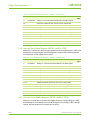
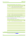
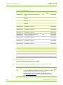
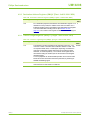
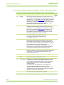
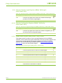
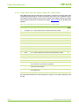
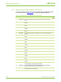
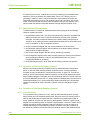
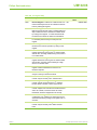
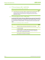
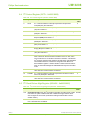
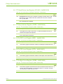
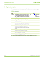
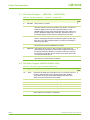
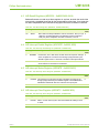
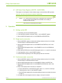
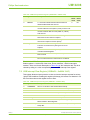
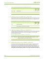
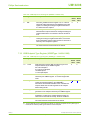
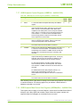
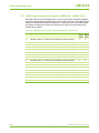
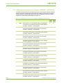
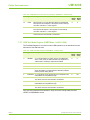
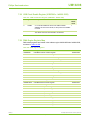
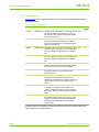
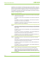
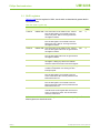
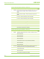
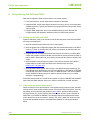
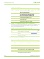
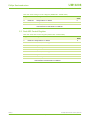
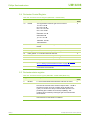
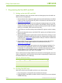
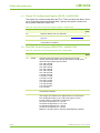
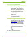
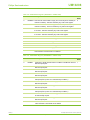
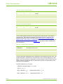
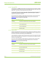
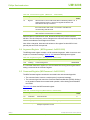
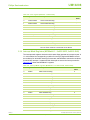
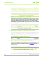
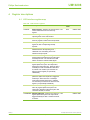
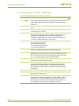
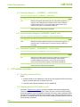
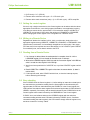
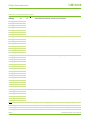
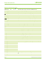
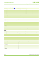
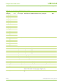
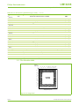
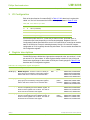
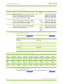
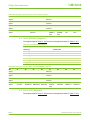
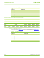
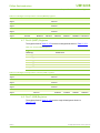
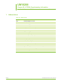
Table 20–275 lists the LPC288x registers associated with I2S input. Subsequent sections
describe the registers in greater detail.
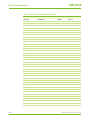
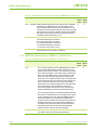
Table 275. DAI registers
Name
Address
Description
SIOCR
0x8020 0384
Stream I/O Configuration Register. This register R/W
is shared with the Dual ADC, I2S out, and Dual
DAC blocks, and includes an output-enable bit that
must be set if the DAI is to be used in Master
mode.
0x180
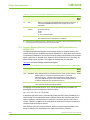
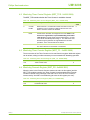
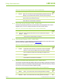
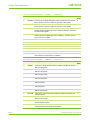
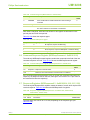
I2S_FMT
0x8020 0380
R/W
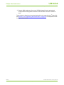
I2S Format Register. This register is shared with
the DAO block. For the DAI, it controls how data is
captured from the DATI pin.
0xDD
UM10208_1
User manual
Access Reset
value
© Koninklijke Philips Electronics N.V. 2006. All rights reserved.
Rev. 01 — 5 September 2006
233 of 338