1
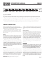
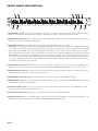
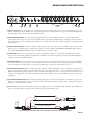
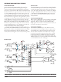
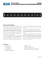
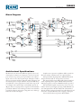
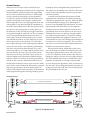
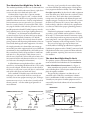
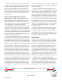
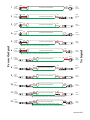
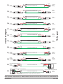
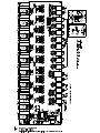
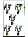
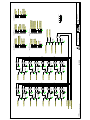
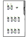
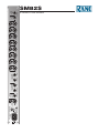
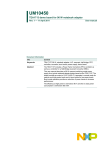
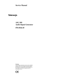
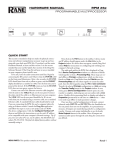
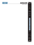
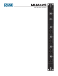
SM82S
STEREO LINE MIXER
CONTENTS (in order of appearance)
Important Safety Instructions
SM82S Manual
SM82S Data Sheet
Sound System Interconnection
Schematics
Warranty
Declaration of Conformity
22372
IMPORTANT SAFETY INSTRUCTIONS
1. Read these instructions.
2. Keep these instructions.
3. Heed all warnings.
4. Follow all instructions.
5. Do not use this apparatus near water.
6. Clean only with a dry cloth.
7. Do not block any ventilation openings. Install in accordance with manufacturer’s instructions.
8. Do not install near any heat sources such as radiators, registers, stoves, or other apparatus (including amplifiers) that produce heat.
9. Do not defeat the safety purpose of the polarized or grounding-type plug. A polarized plug has two blades with one wider than the other. A
grounding-type plug has two blades and a third grounding prong. The wide blade or third prong is provided for your safety. If the provided plug
does not fit into your outlet, consult an electrician for replacement of the obsolete outlet.
10. Protect the power cord and plug from being walked on or pinched particularly at plugs, convenience receptacles, and the point where it exits from
the apparatus.
11. Only use attachments and accessories specified by Rane.
12. Use only with the cart, stand, tripod, bracket, or table specified by the manufacturer, or sold with the apparatus. When a cart is used, use caution
when moving the cart/apparatus combination to avoid injury from tip-over.
13. Unplug this apparatus during lightning storms or when unused for long periods of time.
14. Refer all servicing to qualified service personnel. Servicing is required when the apparatus has been damaged in any way, such as power supply
cord or plug is damaged, liquid has been spilled or objects have fallen into the apparatus, the apparatus has been exposed to rain or moisture, does
not operate normally, or has been dropped.
15. The plug on the power cord is the AC mains disconnect device and must remain readily operable. To completely disconnect this apparatus from
the AC mains, disconnect the power supply cord plug from the AC receptacle.
16. This apparatus shall be connected to a mains socket outlet with a protective earthing connection.
17. When permanently connected, an all-pole mains switch with a contact separation of at least 3 mm in each pole shall be incorporated in the
electrical installation of the building.
18. If rackmounting, provide adequate ventilation. Equipment may be located above or below this apparatus, but some equipment (like large power
amplifiers) may cause an unacceptable amount of hum or may generate too much heat and degrade the performance of this apparatus.
19. This apparatus may be installed in an industry standard equipment rack. Use screws through all mounting holes to provide the best support.
WARNING: To reduce the risk of fire or electric shock, do not expose this apparatus to rain or moisture. Apparatus shall not be exposed to dripping
or splashing and no objects filled with liquids, such as vases, shall be placed on the apparatus.
WARNING
The symbols shown below are internationally accepted symbols
that warn of potential hazards with electrical products.
CAUTION
RISK OF ELECTRIC SHOCK
DO NOT OPEN
ATTENTION: RISQUE DE CHOCS ELECTRIQUE - NE PAS OUVRIR
To reduce the risk of electrical shock, do not open the unit. No user
serviceable parts inside. Refer servicing to qualified service personnel.
This symbol indicates that a dangerous voltage
constituting a risk of electric shock is present
within this unit.
This symbol indicates that there are important
operating and maintenance instructions in the
literature accompanying this unit.
WARNING: This product may contain chemicals known to the State of California to cause cancer, or birth defects or other reproductive harm.
NOTE: This equipment has been tested and found to comply with the limits for a Class B digital device, pursuant to part 15 of the FCC Rules.
These limits are designed to provide reasonable protection against harmful interference in a residential installation. This equipment generates, uses
and can radiate radio frequency energy and, if not installed and used in accordance with the instructions, may cause harmful interference to radio
communications. However, there is no guarantee that interference will not occur in a particular installation. If this equipment does cause harmful
interference to radio or television reception, which can be determined by turning the equipment off and on, the user is encouraged to try to correct
the interference by one or more of the following measures:
• Reorient or relocate the receiving antenna.
• Increase the separation between the equipment and receiver.
• Connect the equipment into an outlet on a circuit different from that to which the receiver is connected.
• Consult the dealer or an experienced radio/TV technician for help.
CAUTION: Changes or modifications not expressly approved by Rane Corporation could void the user's authority to operate the equipment.
This Class B digital apparatus complies with Canadian ICES-003.
Cet appareil numérique de la classe B est conforme à la norme NMB-003 du Canada.
INSTRUCTIONS DE SÉCURITÉ
1. Lisez ces instructions.
2. Gardez précieusement ces instructions.
3. Respectez les avertissements.
4. Suivez toutes les instructions.
5. Ne pas utiliser près d’une source d’eau.
6. Ne nettoyer qu’avec un chiffon doux.
7. N’obstruer aucune évacuation d’air. Effectuez l’installation en suivant les instructions du fabricant.
8. Ne pas disposer près d’une source de chaleur, c-à-d tout appareil produisant de la chaleur sans exception.
9. Ne pas modifier le cordon d’alimentation. Un cordon polarisé possède 2 lames, l’une plus large que l’autre. Un cordon avec tresse de masse possède
2 lames plus une 3è pour la terre. La lame large ou la tresse de masse assurent votre sécurité. Si le cordon fourni ne correspond pas à votre prise,
contactez votre électricien.
10. Faites en sorte que le cordon ne soit pas piétiné, ni au niveau du fil, ni au niveau de ses broches, ni au niveau des connecteurs de vos appareils.
11. N’utilisez que des accessoires recommandés par Rane.
12. N’utilisez que les éléments de transport, stands, pieds ou tables spécifiés par le fabricant ou vendu avec l’appareil. Quand vous utlisez une valise de
transport, prenez soin de vous déplacer avec cet équipement avec prudence afin d’éviter tout risque de blessure.
13. Débranchez cet appareil pendant un orage ou si vous ne l’utilisez pas pendant un certain temps.
14. Adressez-vous à du personnel qualifié pour tout service après vente. Celui-ci est nécessaire dans n’importe quel cas où l’appareil est abimé : si le
cordon ou les fiches sont endommagés, si du liquide a été renversé ou si des objets sont tombés sur l’appareil, si celui-ci a été exposé à la pluie ou
l’humidité, s’il ne fonctionne pas correctement ou est tombé.
15. La fiche du cordon d’alimentation sert à brancher le courant alternatif AC et doit absolument rester accessible. Pour déconnecter totalement
l’appareil du secteur, débranchez le câble d’alimentation de la prise secteur.
16. Cet appareil doit être branché à une prise terre avec protection.
17. Quand il est branché de manière permanente, un disjoncteur tripolaire normalisé doit être incorporé dans l’installation électrique de l’immeuble.
18. En cas de montage en rack, laissez un espace suffisant pour la ventilation. Vous pouvez disposer d’autres appareils au-dessus ou en-dessous de celuici, mais certains (tels que de gros amplificateurs) peuvent provoquer un buzz ou générer trop de chaleur au risque d’endommager votre appareil et
dégrader ses performances.
19. Cet appareil peut-être installé dans une baie standard ou un chassis normalisé pour un montage en rack. Visser chaque trou de chaque oreille de
rack pour une meilleure fixation et sécurité.
ATTENTION: afin d’éviter tout risque de feu ou de choc électrique, gardez cet appareil éloigné de toute source d’humidité et d’éclaboussures quelles
qu’elles soient. L’appareil doit également être éloigné de tout objet possédant du liquide (boisson en bouteilles, vases,…).
ATTENTION
CAUTION
RISK OF ELECTRIC SHOCK
DO NOT OPEN
ATTENTION: RISQUE DE CHOCS ELECTRIQUE - NE PAS OUVRIR
Afin d’éviter tout risque de choc électrique, ne pas ouvrir l’appareil.
Aucune pièce ne peut être changée par l’utilisateur. Contactez un
SAV qualifié pour toute intervention.
Les symboles ci-dessous sont reconnus internationalement
comme prévenant tout risque électrique.
Ce symbole indique que cette unité utilise un
voltage élevé constituant un risque de choc
électrique.
Ce symbole indique la présence d’instructions
d’utilisation et de maintenance importantes dans le
document fourni.
REMARQUE: Cet équipement a été testé et approuvé conforme aux limites pour un appareil numérique de classe B, conformément au chapitre 15
des règles de la FCC. Ces limites sont établis pour fournir une protection raisonnable contre tout risque d’interférences et peuvent provoquer une
énergie de radiofréquence s'il n'est pas installé et utilisé conformément aux instructions, peut également provoquer des interférences aux niveaux
des équipements de communication. Cependant, il n'existe aucune garantie que de telles interférences ne se produiront pas dans une installation
particulière. Si cet équipement provoque des interférences en réception radio ou télévision, ceci peut être detecté en mettant l'équipement sous/hors
tension, l'utilisateur est encouragé à essayer de corriger cette interférence par une ou plusieurs des mesures suivantes:
• Réorienter ou déplacer l'antenne de réception.
• Augmenter la distance entre l'équipement et le récepteur.
• Connecter l'équipement à une sortie sur un circuit différent de celui sur lequel le récepteur est branché.
• Consulter un revendeur ou un technicien radio / TV expérimenté.
ATTENTION: Les changements ou modifications non expressément approuvés par Rane Corporation peuvent annuler l'autorité de l'utilisateur à
manipuler cet équipement et rendre ainsi nulles toutes les conditions de garantie.
Cet appareil numérique de classe B est conforme à la norme Canadienne ICES-003.
Cet appareil numérique de classe B est conforme à la norme Canadienne NMB-003.
OPERATORS MANUAL
SM82S
STEREO MIXER
1
10
L
4
5
C
0
R
2
2
SEND PAN
10
OL
6
4
8
0
10
LEVEL
L
5
C
0
R
3
10
OL
6
2
4
8
0
SEND PAN
10
LEVEL
L
5
C
0
R
4
2
SEND PAN
10
OL
6
4
8
0
10
LEVEL
L
5
C
0
R
5
2
SEND PAN
10
OL
6
4
8
0
10
LEVEL
L
5
C
0
R
6
2
SEND PAN
10
OL
6
4
8
0
10
LEVEL
L
5
C
0
R
7
2
SEND PAN
10
OL
6
4
8
0
10
LEVEL
L
5
C
0
R
8
2
SEND PAN
10
OL
6
4
8
0
10
LEVEL
L
5
C
0
R
RETURN
2
SEND PAN
L
OL
6
4
8
0
10
LEVEL
C
2
R
PAN
OUTPUT
L
OL
6
8
0
10
LEVEL
C
4
OL
6
0
10
SM82S
2
R
PAN
STEREO MIXER
8
LEVEL
POWER
QUICK START
No one likes to read manuals. Everyone likes to just start pushing buttons and turning knobs until the desired results magically
emerge. That’s usually OK, and with a very few exceptions, damage is unlikely to result from such procedures with the SM82S.
This product is quite obvious: Input LEVEL controls make Inputs louder or not, the stereo SENDs make things happen at the
LOOP SEND outputs, and so on. No real magic there. You should be aware, however, that if you want to connect a mono source to
the SM82S, use only the LEFT Input of a channel so that the mono source will drive both the Left and the Right channels.
Set the levels of the mixer so that the red lights stay off. If they come on, you are overdoing it and distortion will result.
SM82S CONNECTION
When connecting the SM82S to other components in your
system for the first time, leave the power supply for last. This will
give you a chance to make mistakes and correct them before any
damage is done to your fragile speakers and ears.
If you are making your own cables, or experience any hum
problems after hookup, please refer to the RaneNote, “Sound
System Interconnection” (supplied with this manual and available at rane.com).
INPUTS
The SM82S’s Inputs are unbalanced. This means that standard
¼" connectors on the ends of any good quality cable will work
well between your signal sources, signal processing and amplification. For best rejection of nasty things like hum and RF,
keep input cables under 10 feet (3 meters) in length.
Most sources give you the choice of stereo or mono output.
The mixer gives you the same choice. You will note that nomenclature has been placed beneath the input jacks indicating which
is RIGHT and which is LEFT (MONO). If a source is plugged
only into the Left jack and not into the Right, both Right and
Left channels will be fed with the Left Input. This allows the use
of either stereo or mono sources.
OUTPUTS
The SM82S offers balanced main outputs only. This means that
you may use them as either balanced or unbalanced, the choice
being made by the way the connectors are wired. It’s a good idea
to always use a TRS or stereo connector in the outputs no matter
which mode you are using. If a “mono” connector is used, inserting it into the output will short the ring (–) to ground and could
conceivably cause a small amount of distortion to be placed on
the tip (+). While this is not destructive, it may be significant
WEAR PARTS: This product contains no wear parts.
enough to be audible. Balancing therefore requires that both tip
(+) and ring (–) be wired to the following device. Unbalanced
requires only tip and sleeve connected, leaving the unused ring
open.
EFFECTS DEVICES
External devices which might be used could be either mono in
and out, while some may be mono in and stereo out, while still
others may be stereo on both ends. The SM82S easily accommodates all of these varieties. If your effect is mono on both
ends, connect its input to the SM82S LEFT LOOP SEND and
the effect’s output to the SM82S LEFT LOOP RETURN. This
configuration will sum Right and Left Loop Outputs to the
mono effect input and will sum the mono effect output to the
Left and Right Input buses. A mono-in stereo-out device would
connect to the loop outputs in the same way; however the stereo
outputs connect to the respective LEFT and RIGHT LOOP
RETURNS.
EXPANDING
Connecting two or more SM82Ss together to achieve more than
eight stereo Inputs requires that a stereo cable (tip, ring, sleeve)
be connected between the MAIN EXPAND OUTPUT of the
first mixer and the MAIN EXPAND INPUT of the second.
All 32 inputs will then appear at the main OUTPUT of mixer
number two. Only the first sixteen Inputs will be available at the
main Outputs of mixer number one. Should you wish to have all
Loop buses tied, connect the LOOP SENDS of mixer one to the
LOOP EXPAND INPUT of mixer two. All sixteen stereo sends
will then become active at the LOOP SENDS of the second mixer. The expand Inputs and Outputs are unbalanced signals, so to
prevent hum, keep expand cables under 10 feet (3 meters) in
length.
Manual-1
FRONT PANEL DESCRIPTION
3
2
7
1
10
L
5
C
0
R
2
SEND PAN
4
2
10
OL
6
4
4
8
0
10
LEVEL
L
5
C
0
R
3
2
SEND PAN
10
OL
6
4
8
0
10
LEVEL
L
5
C
0
R
4
2
SEND PAN
10
OL
6
4
8
0
10
LEVEL
L
5
C
0
R
5
2
SEND PAN
10
OL
6
4
8
0
10
LEVEL
L
5
C
0
R
6
2
SEND PAN
10
OL
6
4
8
0
10
LEVEL
L
5
C
0
R
7
2
SEND PAN
10
OL
6
4
8
0
10
LEVEL
L
5
C
0
R
8
2
SEND PAN
10
OL
6
4
8
0
10
LEVEL
L
5
C
0
R
RETURN
SEND PAN
L
OL
6
2
10
LEVEL
1
C
2
R
PAN
OUTPUT
8
0
9
L
OL
6
4
8
0
6 10
10
LEVEL
5
C
4
OL
6
0
10
SM82S
2
R
PAN
STEREO MIXER
8
LEVEL
POWER
8
11
1 Input LEVEL controls: are rotary stereo attenuators that adjust the amount of both Left and Right signals applied to an Input.
Outputs are summed for mixing with all other Inputs. The unity gain position of this control is located at “7.5.”
2 Input OverLoad indicators: glow red whenever its corresponding Input’s output exceeds a level 4 dB below clipping, letting you
know it’s a good idea to turn this Input down a bit.
3 Input PAN controls: operate as ‘PAN’ with a mono signal, and ‘BALANCE’ with a stereo signal.
PAN: When a mono input is used (no plug in the RIGHT Input jack), the signal ‘moves’ from the Left to Right channels. At the
“L” extreme top of travel the sound source is heard from the Left output; at the other “R” extreme bottom it is heard only from the
Right output. In the middle, the sound is heard equally from each output, but is reduced in level by 3 dB relative to its original
value. This guarantees that as the sound is panned from one side to the other, it maintains equal loudness (power) for all positions.
BALANCE: In its center detent, Left and Right signals to each channel are allowed to pass at their original relative levels, therefore preserving the stereo image from devices connected to both of the Inputs. When the control is moved vertically toward the
“L” position, the Right channel level is decreased while the Left channel level is maintained. The opposite occurs if the control is
moved from the detent down toward the “R”.
4 Input SEND Level controls: determine the amount of Post-Fade stereo Input is fed to the Loop Send buses. Each Input’s stereo
SEND is summed on this bus and is available at the respective LEFT and RIGHT LOOP SENDS on the rear of the mixer.
5 RETURN LEVEL control: is a rotary stereo attenuator that controls the amount of Return which is to be added to the Main
Output. The unity gain position of this control is located at “7.5."
6 RETURN OverLoad indicator: glows red whenever the return levels exceed a level of 4 dB below clipping.
7 RETURN PAN control: is a vertical slider that controls the effect or source connected to the LOOP RETURN in the same way
the Input PAN controls work (see 3 above).
8 OUTPUT LEVEL control: is a rotary stereo attenuator that controls the final signal Level at the main OUTPUT jacks. The
unity gain position of this control is located at “7.5".
9 OUTPUT OverLoad indicator: glows red any time the output level exceeds 4 dB below clipping.
q OUTPUT PAN control: is a vertical slider that operates in the same fashion as the PAN control described in item 3 above. It
however, determines the relative levels of the LEFT and RIGHT MAIN OUTPUTS only.
Manual-2
REAR PANEL DESCRIPTION
SM82S
100-240 V
50/60 Hz 7 WATTS
LEFT
COMMERCIAL AUDIO
EQUIPMENT 24TJ
R
MAIN
EXPAND
OUTPUT
UNBALANCED
OUTPUT
BALANCED
LEFT
(MONO)
RANE CORPORATION
LOOP RETURN
UNBALANCED
LOOP SEND
UNBALANCED
RIGHT
RIGHT
TIP=L, RING=R
8
8
7
6
LEFT (MONO)
RIGHT
5
LEFT (MONO)
LEFT
(MONO)
7
RIGHT
LEFT
(MONO)
6
RIGHT
LEFT
(MONO)
LEFT
(MONO)
5
RIGHT
4
RIGHT
LEFT
(MONO)
3
RIGHT
LEFT
(MONO)
2
RIGHT
LEFT
(MONO)
1
ALL INPUTS ARE UNBALANCED
MAIN
EXPAND
INPUT
RIGHT
RIGHT
4
LOOP
EXPAND
INPUT
TIP=L, RING=R
1
2
3
1 Channel Input jacks: consist of eight pairs of unbalanced ¼" tip-sleeve jacks, used to connect any line-level signal source to the
SM82S. As indicated, only the LEFT is to be used if the Input is mono and should therefore appear in both Left and Right channels, depending on the position of the front panel PAN control.
2 MAIN EXPAND INPUT: A ¼" TRS stereo Input jack may link two or more SM82Ss together, or accept the output from
another mixer. This may also be used to sum any fixed-level stereo signal into the Main Outputs, producing a ninth stereo Input
when added with 1. A stereo Tip-Ring-Sleeve cable must be used here. The Left input is on the Tip, Right is on the Ring and the
Sleeve is ground.
3 LOOP EXPAND INPUT: Another ¼" TRS stereo Input, expands the stereo Loop buses of two SM82Ss so they share the same
effects loop. A stereo Tip-Ring-Sleeve cable must be used here. Connect the LEFT and RIGHT LOOP SENDS (4) of the first
unit to the LOOP EXPAND INPUT of the second SM82S. (Tip = left; Ring = right.)
4 LOOP SEND: This pair of ¼" jacks may drive an effect or similar device which is to be returned to item 5 below. If a mono
device is used, both the Left and Right Send channels of the SM82S are summed together and presented at the LEFT Output if
nothing is inserted in the RIGHT Output.
5 LOOP RETURN: These ¼" aux returns may connect the output of a reverb or other effect unit to the Loop bus of the SM82S.
If no effect is used, they can be used as a tenth stereo Input to the mixer in addition to those described in 1 and 2. As with the
other stereo Inputs, mono signal may be connected to the LEFT input to obtain two-channel mono operation.
6 MAIN EXPAND OUTPUT: This ¼" TRS stereo (Tip = left, Ring = right) Output jack connects one SM82S to another for the
purpose of expanding the number of Inputs available. Use only a stereo plug in this jack — a mono jack or cable will cause loss of
Right channel signal and possibly distortion to the Left channel. This Output also serves as a fixed pre-fader level useful as record
outputs or other applications. A send/return cable can be ideal for this output to drive a second amplifier or recorder. See the diagram below.
7 Main BALANCED OUTPUT: These balanced Tip-Ring-Sleeve jacks connect the main Outputs of the SM82S to a power amplifier or to additional signal processing. As is the AES standard with all Rane balanced outputs using ¼" TRS jacks, the Tip is (+),
the Ring is (–) and the Sleeve is ground.
8 Power connector: The internal universal switching power supply operates on any AC mains 100 to 240 VAC, 50 or 60 Hz (most
places in the world). All that is required when traveling is the appropriate IEC line cord.
+
1-CONDUCTOR SHIELDED CABLE
+
LEFT
T = LEFT
R = RIGHT
S = SHIELD
SHIELD
+
SHIELD
1-CONDUCTOR SHIELDED CABLE
+
RIGHT
SHIELD
A Send-Return cable works well to connect other equipment to any of the Expand Inputs or Outputs.
Manual-3
OPERATING INSTRUCTIONS
CIRCUIT DESCRIPTION
Learning to operate the SM82S might be a bit easier if you
glance at the Block Diagram below. All eight stereo Inputs
operate in exactly the same way. Signal applied to the Inputs is
acted on by a radio interference filter (we have assumed that local
broadcasts should not be a part of your music) and is then routed
to a stereo LEVEL control. If you are using a mono source, connect it only to the LEFT Input to send this mono signal to both
the Left and Right sides of the input circuitry. The output of the
Level control sections is applied to a unity gain buffer to prevent
the LEVEL control from adversely interacting with downstream
circuitry. The Input overload sensor monitors here to alert the
user via LED to any possible Input overload conditions. Left and
Right audio is then subjected to the channel PAN control to allow the user to place the stereo image of the source as desired to
the Left and Right Outputs. A stereo SEND control adjusts the
amount of each Input routed to the Loop Output.
All eight stereo Inputs are simultaneously adjusted for stereo
placement by the OUTPUT PAN control. The resultant signal is
added together and fed to the OUTPUT LEVEL control, which
has it’s own Overload indicator. The main Outputs are fully
actively balanced, allowing the use of correctly wired long cables.
EFFECTS LOOP
The LOOP SENDS receive their audio from the Send bus which
is the sum of all the Inputs as determined by the Input SEND
controls. This Output may be used to drive a stereo effects processor. The output of the effect device is returned to the SM82S
through the LOOP RETURNS. The level of the returned effect
is determined by the RETURN LEVEL control on the front
panel. The return section also provides a BALance control for
image placement.
PAN / BALANCE CONTROLS
These operate as ‘PAN’ with a mono signal plugged in the LEFT
input only, and ‘BALANCE’ with a stereo signal (both jacks
plugged in). These do not increase the level of either Left or
Right signal. As the controls are moved toward one channel, the
level of the other channel is only reduced.
HIGH NOISE IMMUNITY
One of the most unusual features of the SM82S is its inherent immunity from noise. All eight of the stereo inputs may be
turned all the way up without increasing the internal noise of
the mixer. This is critical due to the wide variation in output
levels found in musical instruments and tape devices. A fairly
low-level guitar may be combined in the same system with a
high level synthesizer without any undesirable side-effects. The
SM82S eliminates the concerns normally associated with mixing
so-called -l0 dBV units with +4 dBu types.
Block Diagram
INPUT
OVERLOAD
RFI
FILTER
RIGHT
INPUT
INPUT
LEVEL
OUTPUT
LEVEL
OL
SENSE
OUTPUT
BALANCE
RIGHT MAIN
+6 dB
RIGHT SEND
CHANNEL 1
LEFT MAIN
RFI
FILTER
LEFT
INPUT
(MONO)
+6 dB
INPUT
BALANCE
RECEIVE
OVERLOAD
RFI
FILTER
RIGHT
INPUT
RECEIVE
LEVEL
OL
SENSE
+6 dB
LOOP
RETURNS
RFI
FILTER
LEFT
INPUT
(MONO)
LOOP
EXPAND
INPUT
MAIN
EXPAND
INPUT
+6 dB
RING
TIP
RING
TIP
RIGHT
RECEIVE
BALANCE
0 dB
OUTPUT
OVERLOAD
OL
SENSE
+6 dB
RIGHT
SUMMING
AMPLIFIERS
0 dB
MAIN
OUTPUTS
+6 dB
LEFT SEND
SEND
LEVEL
R
CH 2 L R
L
CH 3
R
L
R
L
CH 4
R
L
R
L
CH 5
R
L
R
L
CH 6
R
L
R
L
CH 7
R
L
R
L
CH 8
R
L
R
L
BALANCED
DRIVERS
BALANCED
DRIVERS
LEFT
RIGHT RING
MAIN
EXPAND
OUT
LEFT TIP
RIGHT
0 dB
SUMMING
AMPLIFIERS
LEFT
0 dB
+ L+R
RIGHT
LOOP
SENDS
LEFT
(MONO)
LEFT
RIGHT
LEFT
©Rane Corporation 10802 47th Ave. W., Mukilteo WA 98275-5000 USA TEL 425-355-6000 FAX 425-347-7757 WEB rane.com
Manual-4
107271
DATA SHEET
SM82S
STEREO LINE MIXER
General Description
The Rane SM82S is a product offering incredible power and versatility. It is the equivalent of a sixteen channel mixer in one rack
space. Measuring only 5.25 inches deep, it can do the job of mixers costing several times as much while only occupying a fraction
of the rack space. It is ideally suited for keyboards, synthesizer
expander modules and drum machines, as well as such things as
effects mixing in guitar racks. It also functions as an excellent
submixer for stereo line inputs and effects to a larger console.
Because of shorter internal signal paths, it is much cleaner than
many mixers ten times the cost and size.
Each of the eight Stereo (two channel) input channels feature
a stereo rotary input Level control, a stereo aux Send level control
slider and a left to right Balance control slider. When a single
mono input is used, the Balance control acts as a pan pot. The
aux return section provides a rotary Return Level control and a
slide control for left to right Balance. The output stage includes
a rotary Output Level control and a slide control for left to right
Balance.
The human engineering applied to the SM82S makes it
extremely easy to operate. The segregation of function between
rotary and slide controls (rotary for all input and output Levels
and slide for Balance and Send) makes it simple to use, even in
the dark.
The SM82S is fully expandable using the ¼" TRS Main Expand Input and Output jacks. Expansion is as simple as connecting a stereo ¼" jumper cable from the first unit’s Expand Output
jack to the second unit’s Expand Input jack. Now, two SM82S
units create a 16 channel stereo (32 input) line level Mixer in just
two rack spaces. Or, 24 channel stereo (48 input) Mixer in just
three rack spaces. You get the idea!
Features
•
•
•
•
8 Stereo Input Channels
1 Stereo Auxiliary Send
1 Stereo Auxiliary Return
Stereo Balance / Mono Pan Controls
• Balanced Stereo Output
• Expandable to / from other Mixers
• Internal Universal Voltage Power Supply (100-240 VAC)
Data Sheet-1
SM82S
STEREO LINE MIXER
Parameter
Input Impedance: Ch's 1-8
..........Receive
..........Expand
Input Level: Nominal
..........Minimum
..........Maximum
Input Design
Input Connectors: Ch's 1-8
..........Receive
..........Expand
Input Gain Range
RFI Input Filters
Max Output Level: Main
..........Loop Send
..........Expand
Output Impedance: Main
..........Loop Send
..........Expand
Specification
100k
100k
20k
+4
-10
+26
Unbalanced
¼" mono TS (tip-sleeve)
¼" mono TS
¼" stereo TRS (tip-ring-sleeve)
Off to +6
Yes
+26 (+20)
+20
+20
100
100
100
Output Design: Main
..........Loop Send
..........Expand
Output Connectors
Output Gain Range
Frequency Response
THD + Noise
IM Distortion (SMPTE)
Input Referred Noise
Signal-to-Noise Ratio
Crosstalk
Active Balanced/Unbalanced
Unbalanced
Unbalanced
¼" TRS
Off to +6
20 Hz-20 kHz
.015
.01
-112
98 (re +4 dBu, 20 kHz BW)
76 (1 kHz)
85 (1 kHz)
+16
100 to 240
CE, FCC, CULUS
All Steel
1.75"H x 19"W x 5.3"D
5 lb
4.25" x 20.3" x 13.75"
8 lb
Overload LED Thresholds
Power Supply Requirement
Unit: Conformity
..........Construction
..........Size
..........Weight
Shipping: Size
..........Weight
Note: 0 dBu=0.775 Vrms
Data Sheet-2
Limit
20%
20%
1%
1
1
1
Units
Ω
Ω
Ω
dBu
dBV
dBu
1
dB
1
1
1
1%
1%
1%
dBu
dBu
dBu
Ω
Ω
Ω
Conditions/Comments
Tip=Left; Ring=Right
Balanced (Unbalanced)
Unbalanced
Unbalanced
Each Output
Differential line drivers
2
3
.005
.005
1
2
2
2
1
10%
dB
dB
%
%
dBu
dB
dB
dB
dBu
VAC
Unbalanced
+4 dBu, 20-20 kHz
60 Hz/7 kHz, 4:1, +4 dBu
All inputs max, 50% out level, balanced
Left-Right
Channel to channel
All critical nodes monitored
50/60 Hz, 7W
(4.4 cm x 48.3 cm x 13.5 cm)
(2.3 kg)
(11 cm x 52 cm x 35 cm)
(3.6 kg)
SM82S
STEREO LINE MIXER
Block Diagram
INPUT
OVERLOAD
RFI
FILTER
RIGHT
INPUT
INPUT
LEVEL
OUTPUT
LEVEL
OL
SENSE
OUTPUT
BALANCE
RIGHT MAIN
+6 dB
RIGHT SEND
CHANNEL 1
LEFT MAIN
RFI
FILTER
LEFT
INPUT
(MONO)
+6 dB
INPUT
BALANCE
RECEIVE
OVERLOAD
RFI
FILTER
RIGHT
INPUT
RECEIVE
LEVEL
OL
SENSE
LOOP
RETURNS
RFI
FILTER
LOOP
EXPAND
INPUT
MAIN
EXPAND
INPUT
+6 dB
RING
TIP
RING
TIP
RECEIVE
BALANCE
RIGHT
CH 3
R
L
R
L
CH 4
R
L
R
L
CH 5
R
L
R
L
CH 6
R
L
R
L
CH 7
R
L
R
L
CH 8
R
L
R
L
BALANCED
DRIVERS
+6 dB
RIGHT
SUMMING
AMPLIFIERS
0 dB
MAIN
OUTPUTS
+6 dB
LEFT SEND
SEND
LEVEL
R
CH 2 L R
L
+6 dB
LEFT
INPUT
(MONO)
0 dB
OUTPUT
OVERLOAD
OL
SENSE
BALANCED
DRIVERS
LEFT
RIGHT RING
MAIN
EXPAND
OUT
LEFT TIP
RIGHT
0 dB
SUMMING
AMPLIFIERS
LEFT
0 dB
+ L+R
RIGHT
LOOP
SENDS
LEFT
(MONO)
LEFT
RIGHT
LEFT
Architectural Specifications
The line level stereo mixer unit shall have eight (8) stereo (total
of 16) inputs, one main stereo output pair, one stereo loop send
pair, one stereo loop receive pair, loop and main stereo expand
inputs, and one stereo main expand output. All inputs, as well as
the loop send output, shall be configured such that plugging only
into the left input (or output) will mono the system. Each stereo
input shall have a rotary ganged level control with a range of off
to +6 dB gain and a separate input overload LED. Separate +6
dB gain master rotary ganged stereo output level control shall be
provided. In addition, stereo slider-type balance controls shall be
provided for all inputs and outputs, along with stereo slider-type
send level controls on all inputs.
Complete stereo expansion capabilities shall be provided to
allow any number of similar units to be coupled together.
The inputs shall be high impedance (100 kΩ) unbalanced
designs terminated with ¼" TS (tip-sleeve) connectors.
The outputs shall be active differentially balanced with balanced output impedance equal to 200 Ω terminated with ¼"
TRS (tip-ring-sleeve) connectors. RFI filters shall be provided.
The unit shall be capable of operation by means of its own
built-in universal power supply operating at 100-240 VAC and
meet CE requirements. The unit shall be UL and cUL listed.
The unit shall be constructed entirely from cold-rolled steel, and
mount into a standard EIA relay rack occupying 1 rack-space.
The unit shall be a Rane Corporation Model SM82S.
Data Sheet-3
SM82S
STEREO LINE MIXER
Rear Panel
Studio Example
REVERB / EFFECTS
FROM ANOTHER MIXER
OR SM82S OUTPUTS
8 STEREO
INPUTS (16)
LOOP
SEND
SM82S
LOOP
RETURN
MAIN EXPAND
INPUTS
MAIN EXPAND
OUTPUTS
OUTPUTS
INPUTS
STEREO
AMPLIFIER
COMPUTER SOUND
CARD / INTERFACE
MENU
CD PLAYER
PHONE OR MP3
OUTPUTS
Application Information
The SM82S allows you to mix eight Stereo line level Inputs down
to a main Stereo Output. Additionally you can create a separate
Stereo Loop Send mix for driving any stereo, or mono, external
processor, and then return from this processor into the Stereo
Loop Return Inputs. The stereo Return Level control is used to
set the desired mix of wet and dry signals.
For applications not requiring the looping facilities, the Loop
Return Inputs double as a fully functional 9th Stereo Input,
creating a 9-Input Stereo Mixer! When used this way, the Loop
Send Outputs become a separate Stereo Output pair, useful for
monitor sends, tape outputs, or any other application.
When not used for expansion, the Main Expand Output pair
double as a pre-fader stereo mix, again useful as tape outputs, or
any other fixed-level application.
Mono sources and external processors are handled easily by
the SM82S. Connecting only to any Left Input Jack automatically routes this signal to the Right channel so an equal Left/Right
signal is summed into the mains. Similarly, connecting only to
the Left Loop Send output gives you an equal mono L+R output
send for mono input processors.
©Rane Corporation 10802 47th Ave. W., Mukilteo WA 98275-5000 USA TEL 425-355-6000 FAX 425-347-7757 WEB rane.com
Data Sheet-4
All features & specifications subject to change without notice. 6-2015
RaneNote
SOUND SYSTEM INTERCONNECTION
Sound System
Interconnection
• Cause & prevention of ground loops
• Interfacing balanced & unbalanced
• Proper pin connections and wiring
• Chassis ground vs. signal ground
• Ground lift switches
Rane Technical Staff
Introduction
This note, originally written in 1985, continues to be
one of our most useful references. It’s popularity stems
from the continual and perpetual difficulty of hooking
up audio equipment without suffering through all sorts
of bizarre noises, hums, buzzes, whistles, etc.— not to
mention the extreme financial, physical and psychological price. As technology progresses it is inevitable that
electronic equipment and its wiring should be subject
to constant improvement. Many things have improved
in the audio industry since 1985, but unfortunately
wiring isn’t one of them. However, finally the Audio
Engineering Society (AES) has issued a standards
document for interconnection of pro audio equipment. It is AES48, titled “AES48-2005: AES standard
on interconnections —Grounding and EMC practices
— Shields of connectors in audio equipment containing
active circuitry.”
Rane’s policy is to accommodate rather than dictate. However, this document contains suggestions for
external wiring changes that should ideally only be
implemented by trained technical personnel. Safety
regulations require that all original grounding means
provided from the factory be left intact for safe operation. No guarantee of responsibility for incidental
or consequential damages can be provided. (In other
words, don’t modify cables, or try your own version of
grounding unless you really understand exactly what
type of output and input you have to connect.)
RaneNote 110
© 1985, 1995, 2006, 2007, 2011 Rane Corporation
Interconnection-1
Ground Loops
Almost all cases of noise can be traced directly to
ground loops, grounding or lack thereof. It is important
to understand the mechanism that causes grounding
noise in order to effectively eliminate it. Each component of a sound system produces its own ground internally. This ground is usually called the audio signal
ground. Connecting devices together with the interconnecting cables can tie the signal grounds of the two
units together in one place through the conductors in
the cable. Ground loops occur when the grounds of the
two units are also tied together in another place: via
the third wire in the line cord, by tying the metal chassis together through the rack rails, etc. These situations
create a circuit through which current may flow in a
closed “loop” from one unit’s ground out to a second
unit and back to the first. It is not simply the presence
of this current that creates the hum—it is when this
current flows through a unit’s audio signal ground that
creates the hum. In fact, even without a ground loop, a
little noise current always flows through every interconnecting cable (i.e., it is impossible to eliminate these
currents entirely). The mere presence of this ground
loop current is no cause for alarm if your system uses
properly implemented and completely balanced interconnects, which are excellent at rejecting ground loop
and other noise currents. Balanced interconnect was
developed to be immune to these noise currents, which
can never be entirely eliminated. What makes a ground
loop current annoying is when the audio signal is affected. Unfortunately, many manufacturers of balanced
audio equipment design the internal grounding system
improperly, thus creating balanced equipment that is
not immune to the cabling’s noise currents. This is one
reason for the bad reputation sometimes given to balanced interconnect.
A second reason for balanced interconnect’s bad
reputation comes from those who think connecting
unbalanced equipment into “superior” balanced equipment should improve things. Sorry. Balanced interconnect is not compatible with unbalanced. The small
physical nature and short cable runs of completely
unbalanced systems (home audio) also contain these
ground loop noise currents. However, the currents in
unbalanced systems never get large enough to affect
the audio to the point where it is a nuisance. Mixing
balanced and unbalanced equipment, however, is an
entirely different story, since balanced and unbalanced
interconnect are truly not compatible. The rest of this
note shows several recommended implementations for
all of these interconnection schemes.
The potential or voltage which pushes these noise
currents through the circuit is developed between the
independent grounds of the two or more units in the
system. The impedance of this circuit is low, and even
though the voltage is low, the current is high, thanks to
Mr. Ohm, without whose help we wouldn’t have these
problems. It would take a very high resolution ohm
meter to measure the impedance of the steel chassis or
the rack rails. We’re talking thousandths of an ohm. So
trying to measure this stuff won’t necessarily help you.
We just thought we’d warn you.
BALANCED OUTPUTS
+
–
BALANCED INPUTS
RED
BLACK
SHIELD
+
RED
BLACK
SHIELD
2-CONDUCTOR SHIELDED CABLE
–
G
MALE
G
FEMALE
RED
2
BLACK
3 C 3
SHIELD
1
1
2
T
R
S
CHASSIS
GROUND
Interconnection-2
RED
BLACK
SHIELD
2-CONDUCTOR SHIELDED CABLE
RED
BLACK
SHIELD
2-CONDUCTOR SHIELDED CABLE
RED
BLACK
SHIELD
Figure 1a. The right way to do it.
MALE
2
1
3
FEMALE
2
C 3
1
T
R
S
CHASSIS SIGNAL
GROUND GROUND
The Absolute Best Right Way To Do It
The method specified by AES48 is to use balanced lines
and tie the cable shield to the metal chassis (right where
it enters the chassis) at both ends of the cable.
A balanced line requires three separate conductors, two of which are signal (+ and –) and one shield
(see Figure 1a). The shield serves to guard the sensitive
audio lines from interference. Only by using balanced
line interconnects can you guarantee (yes, guarantee)
hum-free results. Always use twisted pair cable. Chassis tying the shield at each end also guarantees the best
possible protection from RFI [radio frequency interference] and other noises [neon signs, lighting dimmers].
Neil Muncy1, an electroacoustic consultant and
seasoned veteran of years of successful system design,
chairs the AES Standards Committee (SC-05-05)
working on this subject. He tirelessly tours the world
giving seminars and dispensing information on how to
successfully hook-up pro audio equipment2. He makes
the simple point that it is absurd that you cannot go
out and buy pro audio equipment from several different
manufacturers, buy standard off-the-shelf cable assemblies, come home, hook it all up and have it work hum
and noise free. Plug and play. Sadly, almost never is
this the case, despite the science and rules of noise-free
interconnect known and documented for over 60 years
(see References for complete information).
It all boils down to using balanced lines, only balanced lines, and nothing but balanced lines. This is why
they were developed. Further, that you tie the shield to
the chassis, at the point it enters the chassis, and at both
ends of the cable (more on ‘both ends’ later).
Since standard XLR cables come with their shields
tied to pin 1 at each end (the shells are not tied, nor
need be), this means equipment using 3-pin, XLR-type
connectors must tie pin 1 to the chassis (usually called
chassis ground) — not the audio signal ground as is
most common.
Not using signal ground is the most radical departure from common pro-audio practice. Not that there
is any argument about its validity. There isn’t. This is
the right way to do it. So why doesn’t audio equipment
come wired this way? Well, some does, and since 1993,
more of it does. That’s when Rane started manufacturing some of its products with balanced inputs and
outputs tying pin 1 to chassis. So why doesn’t everyone
do it this way? Because life is messy, some things are
hard to change, and there will always be equipment in
use that was made before proper grounding practices
were in effect.
Unbalanced equipment is another problem: it is
everwhere, easily available and inexpensive. All those
RCA and ¼" TS connectors found on consumer equipment; effect-loops and insert-points on consoles; signal
processing boxes; semi-pro digital and analog tape
recorders; computer cards; mixing consoles; et cetera.
The next several pages give tips on how to successfully address hooking up unbalanced equipment.
Unbalanced equipment when “blindly” connected with
fully balanced units starts a pattern of hum and undesirable operation, requiring extra measures to correct
the situation.
The Next Best Right Way To Do It
The quickest, quietest and most foolproof method to
connect balanced and unbalanced is to transformer
isolate all unbalanced connections. See Figure 2.
Many manufacturers provide several tools for this
task, including Rane. Consult your audio dealer to explore the options available.
The goal of these adaptors is to allow the use of
standard cables. With these transformer isolation
boxes, modification of cable assemblies is unnecessary.
Virtually any two pieces of audio equipment can be
successfully interfaced without risk of unwanted hum
and noise.
UNBALANCED
COMMON (WRONG) PRACTICE
(+)
CASE
RECOMMENDED PRACTICE
2
2
3
(–)
3
1
CHASSIS
GROUND
(+)
CASE
OPTIONAL
(–)
NOT CONNECTED
AT CHASSIS
(PLASTIC JACK)
TRANSFORMER
1/4”
TIP-SLEEVE
1
SIGNAL
GROUND
CHASSIS
GROUND
CHASSIS
GROUND
Figure 1b. Recommmended practice.
BALANCED
2
3
1
EARTH GROUNDED
METAL ENCLOSURE
CASE LUG MAY
CONNECT TO
CHASSIS
(NOT REQUIRED)
CHASSIS IS
GROUNDED TO PIN 1
Figure 2. Transformer Isolation
Interconnection-3
Another way to create the necessary isolation is to
use a direct box. Originally named for its use to convert
the high impedance, high level output of an electric
guitar to the low impedance, low level input of a recording console, it allowed the player to plug “directly”
into the console. Now this term is commonly used to
describe any box used to convert unbalanced lines to
balanced lines.
The Last Best Right Way To Do It
If transformer isolation is not an option, special
cable assemblies are a last resort. The key here is to
prevent the shield currents from flowing into a unit
whose grounding scheme creates ground loops (hum)
in the audio path (i.e., most audio equipment).
It is true that connecting both ends of the shield is
theoretically the best way to interconnect equipment
–though this assumes the interconnected equipment is
internally grounded properly. Since most equipment is
not internally grounded properly, connecting both ends
of the shield is not often practiced, since doing so usually creates noisy interconnections.
A common solution to these noisy hum and buzz
problems involves disconnecting one end of the shield,
even though one can not buy off-the-shelf cables with
the shield disconnected at one end. The best end to disconnect is the receiving end. If one end of the shield is
disconnected, the noisy hum current stops flowing and
away goes the hum — but only at low frequencies. A
ground-sending-end-only shield connection minimizes
the possibility of high frequency (radio) interference
since it prevents the shield from acting as an antenna
to the next input. Many reduce this potential RF interference by providing an RF path through a small capacitor (0.1 or 0.01 microfarad ceramic disc) connected
from the lifted end of the shield to the chassis. (This is
referred to as the “hybrid shield termination” where the
sending end is bonded to the chassis and the receiving
end is capacitively coupled. See Neutrik’s EMC-XLR
for example.) The fact that many modern day installers still follow this one-end-only rule with consistent
success indicates this and other acceptable solutions to
FEMALE
2
C
3
1
RED
BLACK
SHIELD
RF issues exist, though the increasing use of digital and
wireless technology greatly increases the possibility of
future RF problems.
If you’ve truly isolated your hum problem to a specific unit, chances are, even though the documentation
indicates proper chassis grounded shields, the suspect
unit is not internally grounded properly. Here is where
special test cable assemblies, shown in Figure 3, really
come in handy. These assemblies allow you to connect
the shield to chassis ground at the point of entry, or to
pin 1, or to lift one end of the shield. The task becomes
more difficult when the unit you’ve isolated has multiple inputs and outputs. On a suspect unit with multiple
cables, try various configurations on each connection
to find out if special cable assemblies are needed at
more than one point.
See Figure 4 for suggested cable assemblies for your
particular interconnection needs. Find the appropriate output configuration (down the left side) and then
match this with the correct input configuration (across
the top of the page.) Then refer to the following pages
for a recommended wiring diagram.
Ground Lifts
Many units come equipped with ground lift switches.
In only a few cases can it be shown that a ground lift
switch improves ground related noise. (Has a ground
lift switch ever really worked for you?) In reality, the
presence of a ground lift switch greatly reduces a unit’s
ability to be “properly” grounded and therefore immune to ground loop hums and buzzes. Ground lifts
are simply another Band-Aid® to try in case of grounding problems. It is true that an entire system of properly grounded equipment, without ground lift switches,
is guaranteed (yes guaranteed) to be hum free. The
problem is most equipment is not (both internally and
externally, AC system wise) grounded properly.
Most units with ground lifts are shipped so the unit
is “grounded” — meaning the chassis is connected to
audio signal ground. (This should be the best and is
the “safest” position for a ground lift switch.) If after
hooking up your system it exhibits excessive hum or
2-CONDUCTOR SHIELDED CABLE
RED
BLACK
SHIELD
MALE
2
3
1
TEST
WIRE
Figure 3. Test cable
Interconnection-4
GROUND CLIP
buzzing, there is an incompatibility somewhere in the
system’s grounding configuration. In addition to these
special cable assemblies that may help, here are some
more things to try:
1. Try combinations of lifting grounds on units supplied with lift switches (or links). It is wise to do this
with the power off!
2. If you have an entirely balanced system, verify all
chassis are tied to a good earth ground, for safety’s
sake and hum protection. Completely unbalanced
systems never earth ground anything (except cable
TV, often a ground loop source). If you have a mixed
balanced and unbalanced system, do yourself a favor
and use isolation transformers or, if you can’t do
that, try the special cable assemblies described here
and expect it to take many hours to get things quiet.
May the Force be with you.
3. Balanced units with outboard power supplies (wall
warts or “bumps” in the line cord) do not ground the
chassis through the line cord. Make sure such units
are solidly grounded by tying the chassis to an earth
ground using a star washer for a reliable contact.
(Rane always provides this chassis point as an external screw with a toothed washer.) Any device with
a 3-prong AC plug, such as an amplifier, may serve
as an earth ground point. Rack rails may or may not
serve this purpose depending on screw locations and
paint jobs.
Floating, Pseudo, and Quasi-Balancing
During inspection, you may run across a ¼" output
called floating unbalanced, sometimes also called psuedo-balanced or quasi-balanced. In this configuration,
the sleeve of the output stage is not connected inside
the unit and the ring is connected (usually through a
small resistor) to the audio signal ground. This allows
the tip and ring to “appear” as an equal impedance,
not-quite balanced output stage, even though the output circuitry is unbalanced.
Floating unbalanced often works to drive either a
balanced or unbalanced input, depending if a TS or
TRS standard cable is plugged into it. When it hums, a
special cable is required. See drawings #11 and #12, and
do not make the cross-coupled modification of tying
the ring and sleeve together.
Winning the Wiring Wars
• Use balanced connections whenever possible, with
the shield bonded to the metal chassis at both ends.
• Transformer isolate all unbalanced connections
from balanced connections.
• Use special cable assemblies when unbalanced lines
cannot be transformer isolated.
• Any unbalanced cable must be kept under 10 feet
(3 m) in length. Lengths longer than this will amplify all the nasty side effects of unbalanced circuitry's
ground loops.
Summary
If you are unable to do things correctly (i.e. use fully
balanced wiring with shields tied to the chassis at both
ends, or transformer isolate all unbalanced signals
from balanced signals) then there is no guarantee that
a hum-free interconnect can be achieved, nor is there a
definite scheme that will assure noise-free operation in
all configurations.
References
1. Neil A. Muncy, “Noise Susceptibility in Analog and Digital Signal Processing Systems,” presented at the 97th AES
Convention of Audio Engineering Society in San Francisco, CA, Nov. 1994.
2. Grounding, Shielding, and Interconnections in Analog
& Digital Signal Processing Systems: Understanding the
Basics; Workshops designed and presented by Neil Muncy
and Cal Perkins, at the 97th AES Convention of Audio
Engineering Society in San Francisco, CA, Nov. 1994.
3. The entire June 1995 AES Journal, Vol. 43, No. 6, available
$6 members, $11 nonmembers from the Audio Engineering Society, 60 E. 42nd St., New York, NY, 10165-2520.
4. Phillip Giddings, Audio System Design and Installation
(SAMS, Indiana, 1990).
5. Ralph Morrison, Noise and Other Interfering Signals
(Wiley, New York, 1992).
6. Henry W. Ott, Noise Reduction Techniques in Electronic
Systems, 2nd Edition (Wiley, New York, 1988).
7. Cal Perkins, “Measurement Techniques for Debugging
Electronic Systems and Their Instrumentation,” The Proceedings of the 11th International AES Conference: Audio
Test & Measurement, Portland, OR, May 1992, pp. 82-92
(Audio Engineering Society, New York, 1992).
8. Macatee, RaneNote: “Grounding and Shielding Audio
Devices,” Rane Corporation, 1994.
9. Philip Giddings, “Grounding and Shielding for Sound and
Video,” S&VC, Sept. 20th, 1995.
10. AES48-2005: AES standard on interconnections —
Grounding and EMC practices — Shields of connectors
in audio equipment containing active circuitry (Audio
Engineering Society, New York, 2005).
Band-Aid is a registered trademark of Johnson & Johnson
Interconnection-5
To Input
CABLE
CONNECTORS
MALE
BALANCED XLR
FEMALE BALANCED XLR
(NOT A TRANSFORMER,
NOR A CROSS-COUPLED
OUTPUT STAGE)
From Output
FEMALE BALANCED XLR
(EITHER A TRANSFORMER
OR A CROSS-COUPLED
OUTPUT STAGE)
¼” BALANCED TRS
(NOT A TRANSFORMER,
NOR A CROSS-COUPLED
OUTPUT STAGE)
¼” BALANCED TRS
(EITHER A TRANSFORMER
OR A CROSS-COUPLED
OUTPUT STAGE)
¼” FLOATING UNBALANCED
TRS (TIP-RING-SLEEVE)
(SLEEVE IN UNIT = NC)
¼” OR 3.5 mm
UNBALANCED
TS (TIP-SLEEVE)
UNBALANCED RCA
(TIP-SLEEVE)
BALANCED
EUROBLOCK
¼" BALANCED
TRS (TIP-RING-SLEEVE)
¼" OR 3.5mm
UNBALANCED
TS (TIP-SLEEVE)
UNBALANCED RCA
1
2
3
4
1
2
5
6
B
B
BALANCED
EUROBLOCK
+ to +
– to –
SHIELD NC
+ to +
– to –
SHIELD NC
+ to +
– to –
7
8
9
10
7
8
11
12
21
22
11
12
GROUND to GROUND
13
14
15
16
23
17
18
19
20
23
+ to +
– to –
+ to +
– to –
24
+ to +
– to –
A
SHIELD ONLY
TO XLR PIN 1
A
SHIELD ONLY
TO TRS SLEEVE
B
A
A
24
B
A
A
SHIELD ONLY
TO EUROBLOCK
+ to +
– to –
SHIELD NC
+ to +
– to –
GROUND to GROUND
Figure 4. Interconnect chart for locating correct cable assemblies on the following pages.
Note: (A) This configuration uses an “off-the-shelf” cable.
Note: (B) This configuration causes a 6 dB signal loss. Compensate by “turning the system up” 6 dB.
Interconnection-6
2-CONDUCTOR SHIELDED CABLE
2
FEMALE
1=SHIELD
RED
2
2=RED
BLACK
C 3
3=BLACK
SHIELD
1
2-CONDUCTOR SHIELDED CABLE
3
FEMALE
1=SHIELD
RED
2
2=RED
C 3
B 3=NC
SHIELD
1
1-CONDUCTOR SHIELDED CABLE
4
FEMALE
1=SHIELD
RED
2
2=RED
C 3
B 3=NC
SHIELD
1
1-CONDUCTOR SHIELDED CABLE
From Output
5
6
FEMALE
1=SHIELD
RED
2
2-CONDUCTOR SHIELDED CABLE
2=RED
BLACK
C 3
3=BLACK
SHIELD
1
CROSS-COUPLED OUTPUT ONLY: CONNECT PIN 1 TO PIN 3 AT THIS END
AND SET GROUND LIFT SWITCH TO ‘GROUNDED’ (IF PRESENT).
7
RED
BLACK
SHIELD
2-CONDUCTOR SHIELDED CABLE
8
T=RED
R=BLACK
S=SHIELD
RED
BLACK
SHIELD
2-CONDUCTOR SHIELDED CABLE
9B
T=RED
R=NC
S=SHIELD
T=RED
10B R=NC
S=SHIELD
T=RED
R=BLACK
S=SHIELD
RED
1-CONDUCTOR SHIELDED CABLE
RED
SHIELD
RED
BLACK
SHIELD
1
3
1=NC
2=RED
3=BLACK
RED
T=RED
S=SHIELD
SHIELD
RED
T=RED
S=SHIELD
SHIELD
RED
BLACK
T=RED
S=BLACK
RED
BLACK
RED
BLACK
N/C
T=RED
S=BLACK
MALE
2
1
3
1=NC
2=RED
3=BLACK
RED
BLACK
N/C
T=RED
R=BLACK
S=NC
RED
T=RED
S=BLACK
RED
1-CONDUCTOR SHIELDED CABLE
2-CONDUCTOR SHIELDED CABLE
2
T=RED
R=BLACK
S=NC
SHIELD
SHIELD
MALE
RED
BLACK
N/C
FEMALE
1=SHIELD
RED
2
2-CONDUCTOR SHIELDED CABLE
BLACK
2=RED
C 3
SHIELD
3=BLACK
1
CROSS-COUPLED OUTPUT ONLY: CONNECT PIN 1 TO PIN 3 AT THIS END
AND SET GROUND LIFT SWITCH TO ‘GROUNDED’ (IF PRESENT).
T=RED
R=BLACK
S=SHIELD
11
RED
BLACK
N/C
SHIELD
RED
BLACK
To Input
1
FEMALE
1=SHIELD
RED
2
2=RED
BLACK
C 3
3=BLACK
SHIELD
1
T=RED
S=SHIELD
T=RED
S=BLACK
CROSS-COUPLED OUTPUT ONLY: CONNECT RING TO SLEEVE
AT THIS END AND SET GROUND LIFT SWITCH TO ‘GROUNDED’ (IF PRESENT).
12
T=RED
R=BLACK
S=SHIELD
RED
RED
2-CONDUCTOR SHIELDED CABLE
BLACK
BLACK
SHIELD
CROSS-COUPLED OUTPUT ONLY: CONNECT RING TO SLEEVE
AT THIS END AND SET GROUND LIFT SWITCH TO ‘GROUNDED’ (IF PRESENT).
T=RED
S=BLACK
Interconnection-7
From Output
14
RED
BLACK
N/C
2-CONDUCTOR SHIELDED CABLE
T=RED
S=BLACK
RED
BLACK
N/C
2-CONDUCTOR SHIELDED CABLE
15A
T=RED
S=SHIELD
16A
T=RED
S=SHIELD
17
18
T=RED
S=BLACK
T=RED
S=BLACK
19A
T=RED
S=SHIELD
20A
T=RED
S=SHIELD
RED
SHIELD
RED
SHIELD
RED
BLACK
1-CONDUCTOR SHIELDED CABLE
RED
1-CONDUCTOR SHIELDED CABLE
SHIELD
1=SHIELD
3 2=RED
3=BLACK
1
2
T=RED
R=BLACK
S=SHIELD
RED
T=RED
S=SHIELD
SHIELD
RED
1-CONDUCTOR SHIELDED CABLE
2-CONDUCTOR SHIELDED CABLE
MALE
RED
BLACK
SHIELD
T=RED
S=SHIELD
SHIELD
RED
BLACK
SHIELD
2-CONDUCTOR SHIELDED CABLE
RED
BLACK
MALE
2
1
3
RED
T=RED
S=SHIELD
RED
1-CONDUCTOR SHIELDED CABLE
SHIELD
T=RED
R=BLACK
A S=SHIELD
RED
BLACK
SHIELD
2-CONDUCTOR SHIELDED CABLE
22A
T=RED
R=BLACK
S=SHIELD
RED
BLACK
SHIELD
2-CONDUCTOR SHIELDED CABLE
23
(ANY UNBALANCED CONNECTOR)
RED
BLACK
T=RED
S=BLACK
2-CONDUCTOR SHIELDED CABLE
T=RED
S=SHIELD
SHIELD
RED
BLACK
SHIELD
RED
BLACK
SHIELD
1=SHIELD
2=RED
3=BLACK
T=RED
R=BLACK
S=SHIELD
RED
BLACK
SHIELD
SHIELD
RED
21
RED
BLACK
SHIELD
To Input
13
T=RED
S=BLACK
MALE
2
1
3
1=SHIELD
2=RED
3=BLACK
T=RED
R=BLACK
S=SHIELD
(CHECK: NO STANDARD POLARITY ON EUROBLOCKS)
RED
+
BLACK
SHIELD
–
(CHECK: NO STANDARD POLARITY ON EUROBLOCKS)
24
–
+
RED
BLACK
SHIELD
RED (ANY UNBALANCED CONNECTOR)
T=RED
BLACK
S=BLACK
CROSS-COUPLED OUTPUT ONLY: CONNECT BLACK TO SHIELD AT THIS END
AND SET GROUND LIFT SWITCH TO ‘GROUNDED’ (IF PRESENT).
2-CONDUCTOR SHIELDED CABLE
©Rane Corporation 10802 47th Ave. W., Mukilteo WA 98275-5000 USA TEL 425-355-6000 FAX 425-347-7757 WEB www.rane.com
Interconnection-8
DOC 102907
J1B
GND
GND
GND
GND
GND
GND
C1
4.7/16v
GND
4.7/16v
C10
R2A
2
100kA
GND
GND
R2C
100kA
100kA
C8
47/50v
20.0k
GND
R6
R10
10.0k
GND
R9
10.0k
20.0k
C15
20.0k
6
5
U2A
7
2 OL
20.0k
47pF
R14
4580
C16
U2B
-15
4580
1
47pF
+15
R12
1 OL
R5
3
7
-15
4580
C14
U1B
1
4580
20.0k
2
6
5
U1A
20.0k
R8
10.0k
GND
R7
10.0k
3
47pF
R13
4.7/16v
C12
2
GND
R4
4.7/16v
C11
47/50v
GND
R2B
5
C7
47/50v
GND
C6
5 R1B
100kA 4.7/16v
R1C
100kA
Z4
2200pF C4 GND
GND
C9
20.0k
C13
20.0k
47pF
+15
R11
R3
100kA 4.7/16v
GND
4.7/16v
C5
47/50v
GND
R1A
2
GND
4.7/16v
Z3
2200pF C3
GND
Z2
2200pF C2
GND
Z1
2200pF
3/23/2012
C:\CAD Projects\sm82s\SM82S-1.SchDoc
LEFT
(MONO)
J2A
INPUT 2
RIGHT
J2B
J1A
LEFT
(MONO)
INPUT 1
RIGHT
D38
D39
D40
D41
1SMB15CAT3 1SMB15CAT3
1SMB15CAT3 1SMB15CAT3
3
1
6
4
3
1
6
4
+
+
+
+
8
4
8
4
D3
4148
D1
4148
GND
R18
90.9k
D4
4148
GND
C18
+ 1/50v
D2
4148
R16
R20
10.0k 10.0k
4.7/16v
C24
2BAL_LEFT
2BAL_RIGHT
4.7/16v
J3A
LEFT
(MONO)
INPUT 3
RIGHT
J3B
1BAL_LEFT
C25
0.1
GND
C23
+15
GND
C19
0.1
GND
-15
GND
R17
90.9k
R19
10.0k
4.7/16v
C22
R15
10.0k
C17
+ 1/50v
C26
0.1
GND
+15
C21
1BAL_RIGHT
4.7/16v
C20
0.1
GND
-15
GND
GND
D42
GND
D43
GND
4.7/16v
C29
47/50v
GND
C30
47/50v
GND
Main
GND
20.0k
GND
R23
C32 GND
R21B
5
100kA 4.7/16v
R25
10.0k
R21C
100kA
R24
10.0k
6
5
3
U3A
7
3 OL
20.0k
47pF
R27
4580
C34
U3B
-15
4580
1
47pF
+15
20.0k
C33
20.0k
2
R26
R22
C31
R21A
2
100kA 4.7/16v
Z6
2200pF C28 GND
GND
4.7/16v
Z5
2200pF C27
3
1
6
4
+
+
8
4
C39
0.1
C38
4.7/16v
J5B
DRAWN BY:
ACTION:
J5A
LEFT
(MONO)
INPUT 5
GND
GND
GND
GND
GND
4.7/16v
GND
RWJ
CHECKED BY:
MR
4.7/16v
GND
GND
R36
47/50v 20.0k
C47
U5A
5 OL
20.0k
47pF
R44
4580
C55
7
-15
4580
1
47pF
+15
20.0k
C54
R43
4 OL
20.0k
47pF
R42
6 U5B
5
7
-15
+15
4.7/16v
C63
R49
90.9k
GND
C57
1/50v
D10
4148
5
114666
5BAL_LEFT
5BAL_RIGHT
4.7/16v
R46
R50
10.0k 10.0k
D8
4148
4BAL_LEFT
C65
0.1
GND
C62
C59
0.1
GND
-15
R47
90.9k
GND
C56
1/50v
D9
4148
D7
4148
4.7/16v
C61
4BAL_RIGHT
4.7/16v
R48
10.0k
GND
+
C64
0.1
R45
10.0k
GND
+
+15
GND
C60
C58
0.1
GND
-15
SM82 INPUTS 1-5
R40
10.0k
GND
R39
10.0k
3
2
1
4580
4580
C53
U4B
10802 47th Avenue West SHEET:
Mukilteo WA 98275-5098 1 of
GND
100kA 4.7/16v
R32C
100kA
R32B
5
C51
R32A C50
2
100kA 4.7/16v
GND
R35
47/50v 20.0k
C46
20.0k
6
5
4.7/16v
R37
10.0k
3 U4A
2
47pF
+15
20.0k
C52
R41
C48
47/50v
GND
Z10
2200pF C43 GND
GND
R33
47/50v 20.0k
C44
C49 GND
R31B
5
R38
100kA 4.7/16v
10.0k
R31C
100kA
GND
GND
C45
R34
4.7/16v
Z9
2200pF C42
GND
GND
R31A
2
100kA
Z8
2200pF C41 GND
GND
4.7/16v
Z7
2200pFC40
ADD D38 THRU D47,
UPDATED TO SMT PARTS,
WAS 109263, SKH 25JAN12
3BAL_LEFT
RIGHT
R29
90.9k
D6
4148
GND
C35
1/50v
D5
4148
GND
3BAL_RIGHT
4.7/16v
R28
R30
10.0k 10.0k
GND
+
+15
LEFT
(MONO)
J4A
INPUT 4
GND
C37
C36
0.1
GND
-15
J4B
RIGHT
D44
D45
D46
D47
4
3
1
6
1SMB15CAT3 1SMB15CAT3
1SMB15CAT3 1SMB15CAT3
3
1
6
+
+
+
+
4
8
4
8
4
1SMB15CAT3 1SMB15CAT3
GND
GND
GND
GND
GND
GND
2
C73
47/50v
GND
R52C
100kA
R60
10.0k
GND
20.0k
GND
R56
4.7/16v
C77
4.7/16v
C76
R59
10.0k
47/50v
6
5
3
20.0k
C80
20.0k
U7A
7
7 OL
20.0k
47pF
R64
4580
C81
U7B
-15
4580
1
47pF
+15
R62
R55
C72
6 OL
20.0k
GND
7
-15
20.0k
GND
1
4580
4580
C79
6 U6B
5
U6A
47/50v
R58
10.0k
GND
R57
10.0k
3
47pF
R63
R52B
4.7/16v
5
GND
100kA
GND
2
GND
R54
4.7/16v
C75
4.7/16v
C74
20.0k
C78
20.0k
47pF
+15
R61
R53
C71
100kA
Z14
2200pF C69 GND
GND
GND
R51C
100kA
R51B
5
100kA
4.7/16v R52A
2
Z13
2200pF C68
GND
4.7/16v
C70
47/50v
GND
4.7/16v R51A
2
GND
100kA
Z12
2200pF C67 GND
Z11
2200pF C66
3/23/2012
C:\CAD Projects\sm82s\SM82S-2.SchDoc
LEFT
(MONO)
J7A
INPUT 7
RIGHT
J7B
LEFT
(MONO)
J6A
INPUT 6
J6B
RIGHT
D48
D49
D50
D51
1SMB15CAT3 1SMB15CAT3
1SMB15CAT3 1SMB15CAT3
3
1
6
4
3
1
6
4
8
4
+
+
+
+
C84
0.1
GND
4.7/16v
C89
R68
90.9k
D14
4148
GND
C83
+ 1/50v
D12
4148
6BAL_LEFT
7BAL_LEFT
7BAL_RIGHT
4.7/16v
GND
C88
C91
0.1
R66
R70
10.0k 10.0k
GND
+15
GND
C85
0.1
-15
GND
R67
90.9k
D13
4148
D11
4148
C82
+ 1/50v
R69
10.0k
4.7/16v
C87
6BAL_RIGHT
4.7/16v
GND
C86
C90
0.1
+15
R65
10.0k
GND
-15
MAIN
J9
EXPAND
LOOP
J8
GND
Main
GND
D57
1SMB15CAT3 GND
D56
1SMB15CAT3 GND
Z18
GND
2200pF
D55
1SMB15CAT3 GND
Z16
GND
2200pF
D54
1SMB15CAT3 GND
Z17
GND
2200pF
Z15
2200pF
20.0k
R74
20.0k
R73
20.0k
R72
20.0k
R71
INPUT 8
J12
GND
GND
GND
GND
GND
GND
4.7/16v
RWJ
CHECKED BY:
MR
4.7/16v
4580
C105
7
-15
C99
47/50v
GND
R84
10.0k
GND
R83
10.0k
7
-15
4580
1
20.0k
47pF
R88
4580
C107
6 U9B
5
U9A
4.7/16v
C115
R93
90.9k
D18
4148
LOOP RETURN LEFT
LOOP RETURN RIGHT
4.7/16v
GND
C114
GND
C109
1/50v
D16
4148
8BAL_LEFT
C117
0.1
R90
R94
10.0k 10.0k
GND
+
+15
C111
0.1
GND
-15
R91
90.9k
D17
4148
GND
C108
1/50v
GND
+
D15
4148
R89
R92
10.0k 10.0k
4.7/16v
C113
8BAL_RIGHT
4.7/16v
GND
C112
C116
0.1
+15
C110
0.1
GND
-15
5
114666
SM82 IN 6-8, LOOP RETURN & EXP
LOOP RETURN OL
20.0k
GND
R80
4.7/16v
C103
4.7/16v
C102
3
20.0k
C106
47pF
+15
R87
20.0k
8 OL
20.0k
R79
2
1
4580
47pF
R86
10802 47th Avenue West SHEET:
Mukilteo WA 98275-5098 2 of
GND
U8A
6 U8B
5
3
C98
R76B
5
100kA
R76C
100kA
GND
R78
R82
10.0k
GND
R81
10.0k
47/50v 20.0k
C97
2
47/50v
GND
GND
R75C
100kA
4.7/16v R76A
2
GND
100kA
Z22
2200pF C95 GND
GND
C101
4.7/16v
C100
20.0k
47pF
+15
R85
20.0k
C104
R77
100kA 4.7/16v
R75B
5
GND
Z21
2200pF C94
GND
C96
47/50v
GND
4.7/16v R75A
2
GND
100kA
Z20
2200pF C93 GND
Z19
2200pF C92
ADD D48 THRU D59,
UPDATED TO SMT PARTS,
WAS 109263, SKH 25JAN12
DRAWN BY:
ACTION:
J13
LEFT
(MONO)
LOOP RETURN
RIGHT
MAIN XPAND LEFT
J10A
LEFT
(MONO)
MAIN XPAND RIGHT
LOOP LEFT
LOOP RIGHT
J10B
RIGHT
D52
D53
D58
D59
8
4
1SMB15CAT3 1SMB15CAT3
1SMB15CAT3 1SMB15CAT3
3
1
6
3
1
6
4
+
+
4
+
+
8
4
8
4
H1
1k
L2
1k
C201
H3
R144
10.0k
Vdd
H4
GND
H5
C188
0.0022
1 OSC
2
4
3
H7
C187
0.068
VIPER50
S
DRAIN
C199
0.001
3
2
C192
1/50v
C200
0.001
-15
R260
1.00k
+
1
+15
4580
47pF
20.0k
C119
R96
3 U10A
2
GND
U38
47pF
7
5 U10B
4580
GND
1 T1
C195
0.0022 X1Y2
C197
0.33 4
C196
20mH
0.0022 X1Y2
0.0022 X1Y2
H2
T 1A 250V
3/23/2012
C:\CAD Projects\sm82s\SM82S-3.SchDoc
GNDP
H6
J11
3
H
2
G
1
N
IEC PWR
F3
LOOP RIGHT
LOOP LEFT
6
R95
20.0k
C118
8
4
2
GND
3
2
GND
5
6
U11A
1
10
9
C189
47/50v
+
+
4
3
2
1
FOD2741
NC
E
C
NC
U36
D27
4148
36.5
D26
MURS160
T2
9
600uH
C190
7
6
10
8
FB
GND
5
6
7
0.001
8
LED
1
2
4
5
COMP
D25
P6SMB160AT
R234
C193
6.8/400v
1BAL_RIGHT
1 OL
1BAL_LEFT
GND
GND
130
R235
130
R236
MURS160
D29
MURS160
D28
10
9
8
7
8
7
5
6
MAIN XPAND LEFT
MAIN XPAND RIGHT
2
6
DF06M
D33
GND
4
5
R107
R105 100
100k
GND
J15
(TO SLIDER PCB J26)
1
4.7/16v
R106
R104 100
100k
4
LOOP LEFT
LOOP RIGHT
-15
4.7/16v
C125
20.0k
R103 GND
511
C126
R101
R102
511
GND
C123
0.1
3
GND
1
+15
4580
47pF
20.0k
C121
R100
+15
C122
0.1
GND
-15
3
2
7
4580
U11B
47pF
J14
(TO SLIDER PCB J23)
1
20.0k
R98
20.0k
R97
R99
20.0k
C120
8
4
R258
10.0k
C185
0.1
R238 R259
1.24k 51.1k
470/25v
+C203
470/25v
+C202
3 OL
4BAL_RIGHT
4BAL_LEFT
3BAL_LEFT
3BAL_RIGHT
2 OL
2BAL_LEFT
LOOP SEND
RIGHT
LOOP SEND
LEFT
(MONO)
Main
10uH
L6
10uH
L5
10
9
8
7
6
5
4
3
2
C183
150/25v
C182
150/25v
GND
J18
(TO SLIDER PCB J27)
1
J17
5
8
2BAL_RIGHT
GND
7
9
4
6
3
2
1
GND
J16
+
+
6 OL
-15
TP2
TP
GND
+15
TP1
TP
6BAL_RIGHT
6BAL_LEFT
5 OL
5BAL_LEFT
4 OL
+15
-15
8 OL
7 OL
MAIN OUT LEFT
7
47pF
20.0k
C131
R112
1
4580
-15
U12A
+15
4580
U12B
51.1k
R110
R113C
100kA
GND
3
R114
47pF
DRAWN BY:
RWJ
1
CHECKED BY:
MR
4580
-15
U13A
+15
C133
6
10.0k
R115
10.0k
20.0k
R121
100k
6
GND
3
2
GND
5
7
47pF
20.0k
C140
R125
1
R135
100
R133
GND
100
R129
100k
GND
4.7/16v
C145
R134
100
R128
100k
GND
4.7/16v
C144
100
R132
C147
0.1
+15
C146
0.1
GND
-15
GND
GND
GND
GND
J22A
5
114666
MAIN
OUTPUT
LEFT
MAIN
OUTPUT
RIGHT
EXPAND OUT
J22B
J21
SM82 PWR & OUTPUTS
4580
-15
U15A
+15
4580
U15B
10802 47th Avenue West SHEET:
Mukilteo WA 98275-5098 3 of
GND
4.7/16v
C135
R123
20.0k
R120
100k
GND
R122
C134
4.7/16v
47pF
47pF
R131
100
R130
R126 R127 100
100k 100k
GND
4.7/16v
4.7/16v
C141
20.0k
C139
OUTPUT OL
MAIN OUT RIGHT
MAIN OUT LEFT
OUT BAL RIGHT
OUT BAL LEFT
LOOP RETURN OL
C143
0.1
GND
C142
C132
4148
R113B 4
100kA
2
7
4580
U14B
47pF
20.0k
C137
R119
+15
C138
0.1
GND
-15
R124
4148
D19
1
4580
-15
U14A
LOOP RETURN LEFT
7
5 U13B
4580
6
GND
5
6
GND
3
2
47pF
+15
LOOP RETURN RIGHT
20.0k
R117
20.0k
R116
20.0k
C136
R118
R113A
100kA
1
3
GND
GND
D20
10
9
8
7
6
5
4
3
2
UPDATED TO SMT PARTS,
WAS 109263, SKH 25JAN12
4.7/16v
ACTION:
R108
90.9k
51.1k
R109
GND
GND
C128
GND
1/50v
C129 +
GND
3
2
GND
5
6
J20
(TO SLIDER PCB J25)
1
4.7/16v
C127
8BAL_RIGHT
8BAL_LEFT
7BAL_LEFT
MAIN OUT RIGHT
GND
1k
L4
1k
L3
7BAL_RIGHT
OUTPUT OL
10
9
8
7
6
5
4
3
2
J19
(TO SLIDER PCB J24)
1
5BAL_RIGHT
OUT BAL RIGHT
MAIN XPAND RIGHT
OUT BAL LEFT
MAIN XPAND LEFT
47pF
20.0k
C130
R111
8
4
8
4
L1
5 COMP
3
4
2
5
8
4
8
4
3/23/2012
C:\CAD Projects\sm82s\SM82S-4.SchDoc
MAIN XPAND-RIGHT
LOOP-RIGHT
MAIN XPAND-LEFT
LOOP-LEFT
4-BAL_LEFT
4-BAL_RIGHT
3-BAL_LEFT
3-BAL_RIGHT
2-BAL_LEFT
2-BAL_RIGHT
1-BAL_LEFT
1-BAL_RIGHT
1
GNDS
43
R136C
100kMN
5
R136B
100kMN
2
R136A
100kMN
GNDS
GNDS
GNDS
GNDS
R139C
100kMN
5
R139B
100kMN
2
R139A
100kMN
GNDS
R138C
100kMN
5
R138B
100kMN
2
R138A
100kMN
GNDS
R137C
100kMN
5
R137B
100kMN
2
R137A
100kMN
GNDS
6
1
43
6
1
43
6
1
43
6
3
R157
R158
R149
R159
R152
R160
R155
GNDS
20.0k
R143B R156
5
100kA 20.0k
R143C
100kA
GNDS
R143A 20.0k
R154
2
100kA 20.0k
GNDS
R142C
100kA
R142B 20.0k
R153
5
100kA 20.0k
GNDS
R142A 20.0k
R151
2
100kA 20.0k
GNDS
R141C
100kA
R141B 20.0k
R150
5
100kA 20.0k
GNDS
R141A 20.0k
R148
2
100kA 20.0k
GNDS
R140C
100kA
R140B 20.0k
R147
5
100kA 20.0k
R146
R140A 20.0k
R145
2
100kA 20.0k
GNDS
1
6
4
3
1
6
4
3
1
6
4
3
1
6
4
8-BAL_LEFT
8-BAL_RIGHT
7-BAL_LEFT
7-BAL_RIGHT
6-BAL_LEFT
6-BAL_RIGHT
5-BAL_LEFT
5-BAL_RIGHT
1
GNDS
43
R161C
100kMN
5
R161B
100kMN
2
R161A
100kMN
GNDS
GNDS
GNDS
GNDS
R164C
100kMN
5
R164B
100kMN
2
R164A
100kMN
GNDS
R163C
100kMN
5
R163B
100kMN
2
R163A
100kMN
GNDS
R162C
100kMN
5
R162B
100kMN
2
R162A
100kMN
GNDS
6
1
43
6
1
43
6
1
43
6
3
R181
R182
R173
R183
R176
R184
R179
SLIDER
GNDS
R168B 20.0k
R180
5
100kA 20.0k
R168C
100kA
GNDS
R168A 20.0k
R178
2
100kA 20.0k
GNDS
R167B 20.0k
R177
5
100kA 20.0k
R167C
100kA
GNDS
R167A 20.0k
R175
2
100kA 20.0k
GNDS
R166B 20.0k
R174
5
100kA 20.0k
R166C
100kA
GNDS
R166A 20.0k
R172
2
100kA 20.0k
GNDS
R165C
100kA
R165B 20.0k
R171
5
100kA 20.0k
R170
R165A 20.0k
R169
2
100kA 20.0k
GNDS
1
6
4
3
1
6
4
3
1
6
4
3
1
6
4
GNDS
LOOP RETURN-LEFT
LOOP RETURN-RIGHT
OUT BAL-LEFT
R186C
100kMN
5
R186B
100kMN
RWJ
GNDS
R188
20.0k
R187
20.0k
GNDS
CHECKED BY:
MR
4-BAL_LEFT
10
9
GNDS
5
6-OL
6-BAL_RIGHT
6-BAL_LEFT
5-OL
5-BAL_LEFT
4-OL
5-BAL_RIGHT
114666
SM82 SLIDERS
GNDS
H11 H12 H13 H14
MAIN OUTPUT-OL
MAIN OUT-RIGHT
MAIN OUT-LEFT
OUT BAL-RIGHT
OUT BAL-LEFT
LOOP RETURN-OL
LOOP RETURN-LEFT
LOOP RETURN-RIGHT
3-OL
10802 47th Avenue West SHEET:
Mukilteo WA 98275-5098 4 of
MAIN OUT-LEFT
MAIN OUT-RIGHT
10
9
8
7
6
5
4
3
2
J25
(FROM MAIN PCB J20)
1
10
4-BAL_RIGHT
8
9
7
6
5
8
3-BAL_LEFT
3-BAL_RIGHT
7
6
5
4
2-OL
4
2
3
2-BAL_LEFT
2-BAL_RIGHT
J27
(FROM MAIN PCB J18)
1
3
2
J26
(FROM MAIN PCB J15)
1
NO CHG THIS PAGE
WAS 109263, SKH 25JAN12
GNDS
DRAWN BY:
ACTION:
GNDS
2
R186A
100kMN
GNDS
R185C
100kMN
5
R185B
100kMN
2
R185A
100kMN
+15S
-15S
8-OL
7-OL
8-BAL_RIGHT
8-BAL_LEFT
7-BAL_LEFT
7-BAL_RIGHT
1-BAL_RIGHT
1-OL
1-BAL_LEFT
MAIN XPAND-LEFT
MAIN XPAND-RIGHT
LOOP-LEFT
LOOP-RIGHT
GNDS
GNDS
OUT BAL-RIGHT
10
9
8
7
6
5
4
3
2
J24
(FROM MAIN PCB J19)
1
10
9
8
7
6
5
4
3
2
J23
(FROM MAIN PCB J14)
1
1
43
6
1
43
6
RED
RED
D24
OL
D23
OL
GNDS
-15S
D22
OL
D21
OL
C148
0.1
RED
RED
3/23/2012
C:\CAD Projects\sm82s\SM82S-5.SchDoc
-15S
-15S
-15S
-15S
072
7
-15S
072
1
+15S
20.0k
R196
10.0k
R195
20.0k
R194
10.0k
R193
GNDS
U16A
U16B
2
5
6
3
2
072
7
-15S
U17B
5
6
U17A
3
072
1
+15S
C149
0.1
+15S
20.0k
R192
10.0k
R191
20.0k
R190
10.0k
R189
8
4
8
4
GNDS
R200
10.0k
4-OL
GNDS
R199
10.0k
3-OL
GNDS
R198
10.0k
2-OL
GNDS
R197
10.0k
1-OL
-15S
-15S
-15S
-15S
-15S
D30
OL
D37
OL
RED
RED
D32
OL
D31
OL
072
7
-15S
072
1
+15S
20.0k
R208
10.0k
R207
20.0k
R206
10.0k
R205
072
7
-15S
072
1
GNDS
+15S
C151
0.1
+15S
20.0k
R204
10.0k
R203
20.0k
R202
10.0k
R201
SLIDER
GNDS
C150
0.1
RED
RED
U18A
8
U18B
4
U19A
8
U19B
4
5
6
3
2
5
6
3
2
GNDS
R212
10.0k
8-OL
GNDS
R211
10.0k
7-OL
GNDS
R210
10.0k
6-OL
GNDS
R209
10.0k
5-OL
RWJ
CHECKED BY:
NO CHG THIS PAGE
WAS 109263, SKH 25JAN12
DRAWN BY:
ACTION:
MR
-15S
-15S
-15S
D34
OL
D35
OL
R215
U20A
D36
POWER
YEL
5
6
3
2
GNDS
R220
10.0k
MAIN OUTPUT-OL
GNDS
R219
10.0k
LOOP RETURN-OL
5
114666
SM82 OVERLOADS
GNDS
R218
5.11k
U20B
R217
5.11k
20.0k
R216
072
7
+15S
GNDS
10.0k
-15S
072
1
+15S
C153
0.1
+15S
20.0k
R214
10.0k
R213
10802 47th Avenue West SHEET:
Mukilteo WA 98275-5098 5 of
RED
GNDS
C152
0.1
RED
8
4
WARRANTY
FACTORY AUTHORIZED SERVICE
Your unit may be serviced by the Rane Factory or any Authorized Rane Service Center. To find a Service Center near you, please call
the Rane factory, or check the Rane website. Please do not return your unit to Rane without prior authorization.
Rane Corporation
To obtain service or a Return Authorization, please phone 425-355-6000
or Fax 425-347-7757
The current list of U.S. Rane Authorized Service Centers is found on our website: www.rane.com/service.html
LIMITED DOMESTIC WARRANTY
RANE CORPORATION WARRANTS ALL RANE PRODUCTS (EXCEPT THOSE ITEMS CLASSIFIED AS WEAR PARTS, AND LISTED ON THE
MANUAL-1 PAGE OF EACH OPERATORS MANUAL) PURCHASED IN THE USA AGAINST DEFECTS IN MATERIAL OR WORKMANSHIP
FOR A PERIOD OF TWO (2) YEARS. WEAR PARTS ARE LIMITED TO A PERIOD OF NINETY (90) DAYS FROM THE INITIAL DATE OF
RETAIL PURCHASE FROM AN AUTHORIZED RANE DEALER—WEAR PARTS REQUIRE PROOF OF PURCHASE DATE. This limited
warranty extends to all purchasers or owners of the product during the warranty period beginning with the original retail purchase. Rane Corporation
does not, however, warrant its products against any and all defects: 1) arising out of material or workmanship not provided or furnished by Rane, or
2) resulting from abnormal use of the product or use in violation of instructions, or 3) in products repaired or serviced by other than authorized Rane
repair facilities, or 4) in products with removed or defaced serial numbers, or 5) in components or parts or products expressly warranted by another
manufacturer. Rane agrees to supply all parts and labor to repair or replace defects covered by this limited warranty with parts or products of original
or improved design, at its option in each respect, if the defective product is shipped prior to the end of the warranty period to any Rane authorized
warranty repair facility in the U.S. or to the Rane factory in the original packaging or a replacement supplied by Rane, with all transportation costs and
full insurance paid each way by the purchaser or owner.
LIMITED WARRANTY OUTSIDE THE U.S.A.
RANE PRODUCTS ARE WARRANTED ONLY IN THE COUNTRY WHERE PURCHASED, THROUGH THE AUTHORIZED RANE
DISTRIBUTOR IN THAT COUNTRY, AGAINST DEFECTS IN MATERIAL OR WORKMANSHIP, THE SPECIFIC PERIOD OF THIS
LIMITED WARRANTY SHALL BE THAT WHICH IS DESCRIBED TO THE ORIGINAL RETAIL PURCHASER BY THE AUTHORIZED
RANE DEALER OR DISTRIBUTOR AT THE TIME OF PURCHASE. Rane Corporation does not, however, warrant its products against any and
all defects: 1) arising out of materials or workmanship not provided or furnished by Rane, or 2) resulting from abnormal use of the product or use in
violation of instructions, or 3) in products repaired or serviced by other than authorized Rane repair facilities, or 4) in products with removed or defaced
serial numbers, or 5) in components or parts or products expressly warranted by another manufacturer. Rane agrees, through the applicable authorized
distributor, to repair or replace defects covered by this limited warranty with parts or products of original or improved design, at its option in each respect,
if the defective product is shipped prior to the end of the warranty period to the designated authorized Rane warranty repair facility in the country
where purchased, or to the Rane factory in the U.S., in the original packaging or a replacement supplied by Rane, with all transportation costs and full
insurance paid each way by the purchaser or owner.
ALL REMEDIES AND THE MEASURE OF DAMAGES ARE LIMITED TO THE ABOVE SERVICES, IT IS POSSIBLE THAT ECONOMIC
LOSS OR INJURY TO PERSON OR PROPERTY MAY RESULT FROM THE FAILURE OF THE PRODUCT; HOWEVER, EVEN IF RANE
HAS BEEN ADVISED OF THIS POSSIBILITY, THIS LIMITED WARRANTY DOES NOT COVER ANY SUCH CONSEQUENTIAL OR
INCIDENTAL DAMAGES. SOME STATES OR COUNTRIES DO NOT ALLOW THE LIMITATIONS OR EXCLUSION OF INCIDENTAL
OR CONSEQUENTIAL DAMAGES, SO THE ABOVE LIMITATION MAY NOT APPLY TO YOU.
ANY AND ALL WARRANTIES, EXPRESS OR IMPLIED, ARISING BY LAW, COURSE OF DEALING, COURSE OF PERFORMANCE, USAGE
OF TRADE, OR OTHERWISE, INCLUDING BUT NOT LIMITED TO IMPLIED WARRANTIES OF MERCHANTABILITY AND FITNESS
FOR A PARTICULAR PURPOSE, ARE LIMITED TO A PERIOD OF TWO (2) YEARS FROM EITHER THE DATE OF ORIGINAL RETAIL
PURCHASE OR, IN THE EVENT NO PROOF OF PURCHASE DATE IS AVAILABLE, THE DATE OF MANUFACTURE, SOME STATES
OR COUNTRIES DO NOT ALLOW LIMITATIONS ON HOW LONG AN IMPLIED WARRANTY LASTS, SO THE ABOVE LIMITATIONS
MAY NOT APPLY TO YOU. THIS LIMITED WARRANTY GIVES YOU SPECIFIC LEGAL RIGHTS, AND YOU MAY ALSO HAVE OTHER
RIGHTS WHICH VARY FROM STATE TO STATE, COUNTRY TO COUNTRY.
Warranty-1
WARRANTY PROCEDURE - Only Valid in the USA
NOTICE! You must complete and return the warranty card or register your
product online to extend the Warranty from 2 years to 3 years!
TO VALIDATE YOUR EXTENDED WARRANTY: Use the postcard that came in the box with your unit, or go to www.rane.com and
click on New Product Registration. Fill out the warranty completely, being sure to include the model and serial number of the unit
since this is how warranties are tracked. If your Rane product was purchased in the USA, mail the completed card or register online with
to Rane Corporation within 10 days from the date of purchase. If you purchased the product outside the USA you must file your
warranty registration with the Rane Distributor in that country. It is advised that you keep your bill of sale as proof of purchase,
should any difficulties arise concerning the registration of the warranty card. NOTICE: IT IS NOT NECESSARY TO REGISTER IN
ORDER TO RECEIVE RANE CORPORATION’S STANDARD TWO YEAR LIMITED WARRANTY.
WARRANTY REGISTRATION is made and tracked by model and serial numbers only, not by the purchaser’s or owner’s name.
Therefore any warranty correspondence or inquires must include the model and serial number of the product in question. Be sure to fill
in the model and serial number in the space provided below and keep this in a safe place for future reference.
WARRANTY SERVICE MUST BE PERFORMED ONLY BY AN AUTHORIZED RANE SERVICE FACILITY LOCATED IN
THE COUNTRY WHERE THE UNIT WAS PURCHASED, OR (if product was purchased in the USA) AT THE RANE FACTORY
IN THE USA. If the product is being sent to Rane for repair, please call the factory for a Return Authorization number. We recommend
advance notice be given to the repair facility to avoid possible needless shipment in case the problem can be solved over the phone.
UNAUTHORIZED SERVICE PERFORMED ON ANY RANE PRODUCT WILL VOID ITS EXISTING FACTORY WARRANTY.
FACTORY SERVICE
If you wish your Rane product to be serviced at the factory, it must be shipped fully insured, in the original packing box or equivalent.
This warranty will not cover repairs on products damaged through improper packaging. If possible, avoid sending products through the
mail. Be sure to include in the package:
1. Complete return street shipping address (P.O. Box numbers are not acceptable).
2. A detailed description of any problems experienced, including the make and model numbers of any other system equipment.
3. Remote power supply, if applicable.
Repaired products purchased in the U.S. will be returned prepaid freight via the same method they were sent to Rane. Products purchased
in the USA, but sent to the factory from outside the USA must include return freight funds, and the sender is fully responsible for all
customs procedures, duties, tariffs and deposits.
In order to qualify for Rane’s one year extended warranty (for a total of 3
years parts and labor), the warranty must be completely filled out and sent to
us immediately. Valid in USA only.
We recommend you write your serial number here in your owners
manual and on your sales receipt for your records.
SERIAL NUMBER:______________________________________PURCHASE DATE:__________________________________
©Rane Corporation 10802 47th Ave. W., Mukilteo WA 98275-5000 TEL 425-355-6000 FAX 425-347-7757 WEB www.rane.com
Warranty-2
108360
Declaration of Conformity
Application of
Council Directive(s):
Standard(s) to which
conformity is declared:
2001/95/EC
2002/96/EC
2004/108/EC
2006/95/EC
2011/65/EU
EN60065: 2002/A1:2006/A11:2008/A2:2010/A12:2011
EN55103-1:2009
EN55103-2:2009
EN50581:2012
ENVIRONMENT E2
CE MARK FIRST AFFIXED IN 2006
SERIAL NUMBERS 850000 - 950000
Manufacturer:
Rane Corporation
10802 47th Avenue West
Mukilteo WA 98275-5000 USA
This equipment has been tested and found to be in compliance with all applicable standards and regulations applying to the
EU’s Low Voltage (LV) directive 2006/95/EC, and Electromagnetic Compatibility (EMC) directive 2004/108/EC. In order
for the customer to maintain compliance with this regulation, high quality shielded cable must be used for interconnection to
other equipment. Modification of the equipment, other than that expressly outlined by the manufacturer, is not allowed under
this directive. The user of this equipment shall accept full responsibility for compliance with the LV directive and EMC directive in the event that the equipment is modified without written consent of the manufacturer. This declaration of conformity
is issued under the sole responsibility of Rane Corporation.
Type of Equipment: Professional Audio Signal Processing
Brand: Rane
Model: SM82S
Immunity Results:
THD+N re: 4 dBu, 400 Hz, BW=20-20kHz
Test Description
Results
Conditions
RF Electromagnetic Fields Immunity
80 MHz -1000 MHz, 1 kHz AM, 80% depth, 3V/m
< -46 dB
80 MHz - 100 MHz
< -59 dB100 MHz - 200 MHz
< -53 dB200 MHz - 350 MHz
< -42 dB350 MHz - 550 MHz
< -52 dB550 MHz - 1000 MHz
Conducted RF Disturbances Immunity
150 kHz - 80 MHz, 1 kHz AM, 80% depth, 3V rms
< -61 dB
Power Lines
< -57 dBSignal Lines
Magnetic Fields Immunity
50 Hz - 10 kHz, 4.0 - 0.4 A/m
< -61 dB
I, the undersigned, hereby declare that the equipment specified above conforms
to the Directive(s) and Standard(s) shown above.
(Signature)
Roy G. GIll
Compliance Engineer
(Full Name)
(Position)
November 8, 2006
Mukilteo WA USA
(Date)
(Place)
SM82S
RANE CORPORATION
100-240 V
50/60 Hz 7 WATTS
R
LEFT
RIGHT
OUTPUT
BALANCED
COMMERCIAL AUDIO
EQUIPMENT 24TJ
TIP=L, RING=R
MAIN
EXPAND
OUTPUT
UNBALANCED
LEFT (MONO)
RIGHT
LOOP RETURN
UNBALANCED
LEFT (MONO)
RIGHT
LOOP SEND
UNBALANCED
RIGHT
8
LEFT
(MONO)
RIGHT
7
LEFT
(MONO)
RIGHT
6
LEFT
(MONO)
RIGHT
5
LEFT
(MONO)
RIGHT
4
LEFT
(MONO)
RIGHT
3
LEFT
(MONO)
RIGHT
2
LEFT
(MONO)
RIGHT
1
LEFT
(MONO)
LOOP
EXPAND
INPUT
TIP=L, RING=R
MAIN
EXPAND
INPUT
ALL INPUTS ARE UNBALANCED
SM82S
STEREO LINE MIXER