1
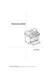
R
Instruction Manual
Before installing and operating this machine, read,
understand and follow all instructions and operating
procedures. Keep these instructions with the machine.
1
TABLE OF CONTENTS
IMPORTANT SAFETY INSTRUCTIONS .......................................................................... 3
PARTS NAMES ................................................................................................................ 6
SPECIFICATIONS ............................................................................................................. 7
OPERATING PROCEDURE ............................................................................................. 9
BLADES REPLACEMENT PROCEDURE ...................................................................... 12
CARBON BRUSHES REPLACEMENT PROCEDURE .................................................. 13
ADDING OIL .................................................................................................................... 14
TROUBLE SHOOTING ................................................................................................... 15
Meaning of "caution" and "warning" indications
Caution:
Indicates a potentially hazardous situation which, if not avoided, may result
in minor or moderate injury. This is also used to alert against unsafe
practices associated with events that could lead to personal injury.
Warning: Indicates a potentially hazardous situation which, if not avoided,
will result in death or serious injury.
*** Ogura & Co., Ltd. shall not be responsible for any incidental damages or
personal injuries resulting from negligence of Warnings and Safety
Instructions contained in the Instruction Manual.
WARNING
Read, understand and follow all safety instructions and operating procedures.
If you do not understand the instructions, or if conditions are not correct for
proper operation, DO NOT OPERATE THE MACHINE. Consult your
supervisor or other responsible person.
WARNING LABELS RELATED SAFETY
Flying debris and loud noise hazards. Wear ear and eye protection.
Hazardous voltage. Disconnect all power before working on this equipment.
Failure to observe this instruction will result in death or serious injury.
Moving blade. Keep hands clear while machine is operating. Turn power
off before servicing.
2
SAVE THESE INSTRUCTIONS
GENERAL POWER TOOL SAFETY WARNINGS
1. Before Operating Tool Read Instruction
Manual.
2. Keep Work Area Clean
• Cluttered areas and benches invite injuries.
3. Consider Work Area Environment
•
•
•
•
Do not expose tool to rain.
Do not use tool in damp or wet locations.
Keep work area well lit.
Do not use tool in presence of flammable liquids
or gases.
4. Guard Against Electric Shock
• Prevent body contact with grounded surfaces,
e.g. pipes, ranges, refrigerator enclosures, etc.
5. Keep Children Away
• Do not allow children or unauthorised personnel
to handle tool or extension cord. All visitors
should be kept away from work area.
6. Store Idle Tools
• When not in use, tools should be stored in a dry and
secure place - out of reach of children.
7. Do Not Force Tool
• It will do the job better and safer at the rate for
which it was intended.
• Do not force tool to work beyond its ability.
Excessive load will cause seizure of the motor,
overheating, smoke and fire.
8. Use Right Tool
• Do not force small tool or attachment to do the
job of a heavy-duty tool.
• Do not use tool for purpose not intended.
9. Dress Properly
• Do not wear loose clothing or jewellery as they
can be caught in moving parts.
• Rubber gloves and non-skid footwear are
recommended when working outdoors.
• Wear protective hair covering to contain long hair.
10. Always Wear Safety Glasses or Goggles
11. Do Not Abuse Power Cord
• Never carry tool by its power cord or pull on the
cord to disconnect it.
• Keep cord away from heat, oil and sharp edges.
12. Secure Work
• Use clamps or a vice to hold the work. This
frees both hands to properly hold, control, and
operate the tool. Failure to properly secure the
work may result in injury.
13. Do Not Overreach
• Keep proper footing and balance at all times.
14. Maintain Tools Carefully
• Keep tools sharp and clean for better and safer
performance.
• Follow instructions for lubricating and changing
accessories.
• Inspect tool power cord periodically and, if
damaged, have repaired by authorized service
facility.
• Keep handles dry, clean, and free from oil and
grease.
15. Disconnect Tools From Power Source
• When not in use, before servicing, and when
changing accessories, such as blades and
cutters.
16. Remove Keys and Wrenches
• Form habit of checking to see that keys and
wrenches are removed from tool before starting
operation.
17. Avoid Unexpected Operation
• Do not carry plugged in tool with finger on
switch.
• Be sure switch is off before plugging in.
18. Use Outdoor Extension Cord For Outside
• When tool is used outdoors, use only extension
cord intended for use outdoors and so marked.
19. Stay Alert
When using electric tools,
• Read and follow operating procedures in this
instruction manual.
• Consider safety of others.
• Operate tool with care.
• Watch what you are doing.
• Use common sense.
• Do not operate tool when you are tired.
3
GENERAL POWER TOOL SAFETY WARNINGS
20. Check For Damaged Parts
• Before using the tool, carefully check all parts
for damage, including guards, to ensure that
they will operate correctly and perform their
intended function.
• Check for any misalignment or binding of
moving parts; damaged or broken parts and
mountings; and any other conditions that may
affect its operation.
• Do not use tool if electric plug or cord is damaged.
Do not use tool if it was dropped or damaged in
any way.
• A guard or other part that is damaged should be
properly repaired or replaced by an authorized
service centre unless otherwise indicated in this
manual.
• Do not use tool if switch does not turn it on and
off. Have damaged or defective switch replaced
by an authorized service centre.
4
21. Only Use Specified Accessories and
Attachments.
• Use only the accessories and attachments
described in this manual and the Ogura
catalogue. Use of other accessories or
attachments may result in an accident or injury.
22. Service at Factory Authorized Repair Centre
Only
• Service this electric appliance in accordance
with the relevant safety regulations.
• Repairs to electric appliances should only be
done by a qualified person. Repairs by others
may endanger the user.
• Contact your dealer to arrange servicing.
23. To throw a way the waste in illegal manner
is strictly prohibited. Follow the local
regulations.
ELECTRO-HYDRAULIC REBAR CUTTER SAFETY WARNINGS
● Cut pieces may fly off during cutting. Confirm the safety of surroundings before cutting.
● Keep fingers and face away from the cutting area. Cut pieces may fly off and cause injury to the operator.
● Material is ejected at end of cut. Be sure that ejected slug cannot fall and cause injury. Consider the
safety of others when cutting.
● Never cut rebar when the piece to be cut off is less than 200 mm in length. Smaller pieces have a
tendency to fly off and may cause injury to the operator and the surroundings.
● Replace any broken, worn, deformed, cracked or damaged parts immediately with Ogura identical replacement
parts. Damaged or broken parts may cause further damage to the tool as well as serious injury to personnel.
● Tool should be connected only to a power supply of the same voltage as indicated on the product label,
and can only be operated on single-phase AC supply.
● If extension cord is used, the wire size should be equal to or greater than that specified below. (Use only
3-wire extension cord that has a 3-pin earthed plug, and 3-pin earthed socket that matches the plug on the
tool.) Replace or repair a damaged cord.
● Always adjust the Hold Bolt to the diameter of the rebar and retighten Hold Nut before cutting.
● Confirm the Hold Nut is tightened properly before cutting starts.
CAUTION
Avoid Electric Shock
● Power source with a breaker is recommended to avoid the electric shock,
Follow Local Noise Level Regulations
● Operate tools within a soundproofed enclosure if necessary.
Check Before Operation
● The tool is manufactured for the purpose of cutting reinforcing bars. Do not use the tool for a purpose it was not
intended for. Only use Ogura genuine blades. Replace parts when and as directed in this instruction manual.
● Confirm that all bolts and screws are tightened properly before operation begins.
Operate Tool With Proper Voltage
● The tool should be connected only to a power supply of the same voltage as indicated on the product label.
If connected to a higher voltage the motor will over speed and eventually burn out. If connected to a lower
voltage the motor will be damaged and eventually break up.
Pay Attention When Operating
● Keep proper footing and balance at all times.
● Stop operation immediately when the tool is out of order or makes abnormal sound during use.
● During tool operation, keep hands and face away from the blades, all moving parts and the scrap ejection section.
● Carbon brushes should be replaced every 200 hours or when the length of the brush is reduced to 6 mm.
Protect Tool
● Handle tool carefully. If it is dropped or struck it could be damaged.
● The motor air vents should be open and unobstructed as they provide cooling for the motor. Keep the air
vents clear of dust, dirt and debris or the motor will over heat and be damaged.
Maintain Tool
● Keep tool clean to stay in best condition. Always wipe off dirt and oil from the motor, switch, and handles.
● Use only Ogura genuine parts for replacement.
● Check the tool regularly so that it can be used safely and effectively.
● Stop operation immediately and contact your dealer if the tool is making abnormal sounds or is out of order in
any way. Do not disassemble the tool as the internal components are sensitive to damage from dust, dirt,
contamination of the hydraulic fluid or improper handling.
● This is a hydraulic tool powered by electricity. When the temperature is low, the oil will thicken and tool may
not work properly. Idle tool for a few minutes before use.
Ear protection
● Typical A-weighted sound pressure level: 96 dB(A)
Typical A-weighted sound power level: 75 dB(A)
CAUTION -Wear ear protection.The typical weighted root mean square acceleration Value is not more than 2.5m/S2
Contact your dealer for service and check-up.
5
PARTS NAMES
HBC-313, 316, 16R
HBC-16R
Stopper
Safety Warning Decal
Motor
Oil Filler Bolt
Hold Bolt
Blade B
Trigger Switch
Blade A
Hydraulic Pump Case
Hydraulic Cylinder
Cutter Rod
Bar Holder
Lock Button
HBC-613, 816
Safety Warning Decal
Note: Do not push this
button during operation
as Cutter Rod will lock
and won't return.
Lever
Oil Filler Bolt
Hold Bolt
Blade A
Motor
Trigger Switch
Hydraulic Pump Case
Blade B
Hydraulic Cylinder
Bar Holder Cutter Rod
HBC-520, 19R, 22, 225, 232
Trigger Switch
Motor
Hold Bolt
Blade A
Safety Warning Decal
Hydraulic Pump Case
Bar Holder
Cutter Rod
Blade B
6
(This lever isn't used
for HBC-613. See
"How to use Switch
for HBC-613" on P11
for the details.)
Hydraulic Cylinder
SPECIFICATIONS
■ Specifications
Model
HBC-313
HBC-613
HBC-316
580 W
710 W
580 W
5.4 Kg
7.3 Kg
5.8 Kg
447 ✕ 151 ✕ 110 mm
378 ✕ 205 ✕ 108 mm
115 V / 230 V a.c
50 / 60 Hz Single-Phase
Weight
Dimensions (L ✕ W ✕ H) 362 ✕ 205 ✕ 106.5 mm
Tensile Strength Max. Dia. Tensile Strength Max. Dia. Tensile Strength Max. Dia.
490 N / mm2
(50 kg / mm2)
Cutting Capacity
13 mm (#4) (50 kg / mm2)
490 N / mm2
13 mm (#4) (50 kg / mm2)
(71,000 P.S.I.)
(71,000 P.S.I.)
(71,000 P.S.I.)
620 N / mm2
620 N / mm2
620 N / mm2
(63 kg / mm2)
Cutting Speed
490 N / mm2
10 mm (#3) (63 kg / mm2)
10 mm (#3) (63 kg / mm2)
(90,000 P.S.I.)
(90,000 P.S.I.)
(90,000 P.S.I.)
1.5 seconds
1.5 seconds
2.0 seconds
16 mm (#5)
13 mm (#4)
Carrying case
Hydraulic oil #46
Standard Accessories
Hex wrenches (3, 4, 5 mm)
Double open end wrenches (14•17 mm)
Model
HBC-816
HBC-16R
HBC-19R
1,010 W
580 W
700 W
115 V / 230 V a.c
50 / 60 Hz Single-Phase
Weight
8.8 Kg
Dimensions (L ✕ W ✕ H) 492 ✕ 165 ✕ 120 mm
6.2 Kg
11.4 Kg
410 ✕ 205 ✕ 180 mm
401 ✕ 126 ✕ 226 mm
Tensile Strength Max. Dia. Tensile Strength Max. Dia. Tensile Strength
440 N / mm
(45 kg / mm2)
Cutting Capacity
620 N / mm2
(63 kg / mm2)
16 mm (#5)
620 N / mm2
(63,000 P.S.I.)
16 mm (#5)
(90,000 P.S.I.)
Max. Dia.
2
(63 kg / mm2)
620 N / mm2
(63 kg / mm2)
13 mm (#4)
19 mm (#6)
(90,000 P.S.I.)
(90,000 P.S.I.)
Cutting Speed
1.5 seconds
2.0 seconds
2.5 seconds
Carrying case
Hydraulic oil #46
Standard Accessories Hex wrenches (3, 4, 5 mm)
Hex wrenches (3, 4, 5, 6 mm)
Double open end wrenches (14•17 mm)
Double open end
wrenches (17•19 mm)
7
Specifications
Model
HBC-520
HBC-22
1,330 W
700 W
115 V / 230 V a.c
50 / 60 Hz Single-Phase
Weight
12.2 Kg
14.2 Kg
Dimensions (L ✕ W ✕ H) 396 ✕ 112 ✕ 220 mm
414 ✕ 112 ✕ 238 mm
Tensile Strength Max. Dia. Tensile Strength
560 N / mm
(57 kg / mm2)
Cutting Capacity
620 N / mm2
Max. Dia.
2
22 mm (#7)
(81,000 P.S.I.)
(63 kg / mm2)
20 mm (#6)
(90,000 P.S.I.)
620 N / mm2
(63 kg / mm2)
19 mm (#6)
(90,000 P.S.I.)
Cutting Speed
2.5 seconds
3.0 seconds
Carrying case
Hydraulic oil #46
Standard Accessories
Hex wrenches (3, 4, 5, 6 mm)
Double open end
wernches (17•19 mm)
Model
Double open end
wernches (17•22 mm)
HBC-225
HBC-232
1,430 W
1,430 W
22.0 Kg
37.6 Kg
115 V / 230 V a.c
50 / 60 Hz Single-Phase
Weight
Dimensions (L ✕ W ✕ H) 480 ✕ 138 ✕ 269 mm
Tensile Strength
Cutting Capacity
620 N / mm2
(63 kg / mm2)
Cutting Speed
Max. Dia.
543 ✕ 167.5 ✕ 289 mm
Tensile Strength Max. Dia.
620 N / mm2
25 mm (#8) (63 kg / mm2)
(90,000 P.S.I.)
(90,000 P.S.I.)
4.0 seconds
7.0 seconds
32 mm (#10)
Carrying case
Hydraulic oil #32
Standard Accessories
Hex wrenches (4, 5, 6, 8 mm) Hex wrenches (4, 5, 6, 8, 10 mm)
Double open end
wernches (14•17•24 mm)
8
Double open end
wernches (17•30 mm)
OPERATING PROCEDURE
Rebar
Blades
This tool is electro-hydraulic rebar cutter to be designed to
cut reinforcing bars.
Read, understand and follow all safety instructions and
operating procedures. If you do not understand the
instructions or if conditions are not correct for proper
operations, do not operate this tool. Consult your
supervisor or other responsible person.
WARNING
1. Before operation, confirm that the position of the
operator, relative to the tool, and the surrounding area
is safe for operation. Put on safety glasses and wear
protective clothing.
2. Refer to the tool specifications in this manual and do
not cut rebar of size or hardness that exceeds the
cutting capacity of the tool.
3. Do not cut material other than rebar. Please ask the
manufacturer if you want to cut other materials.
Hold Bolt
Stopper
HBC-16R
Cutting Procedure.
Rebar
1. Position the rebar to be cut so that it is fully between the
blades as shown in the figure on the left.
WARNING
If the rebar to be cut is not positioned fully between the
blades, the blades will be damaged; the rebar will be
ejected violently and may cause serious personal injury.
Blades
Rebar
Hold Bolt
HBC-16R
Rebar
Hold Bolt
HBC-16R
2. Adjust the Hold Bolt according to the diameter of the
rebar to be cut so that the rebar is at 90 degrees to the
blades as shown in the figure on the left. Tighten the lock
nut. The Hold Bolt supports the rebar and keeps it perpendicular to the blades when cutting.
WARNING
When cutting rebar, adjust the Hold Bolt according to the
thickness (diameter) of the rebar to be cut so that the rebar
is at 90 degrees to the blades as shown in the figure on
the left. Without this adjustment, the cut piece may fly off
and cause serious injury to the operator or bystanders.
3. Confirm that the power supply is 115 V / 230 V single
phase. Insert the plug into the power outlet and connect
the plug to ground (does not apply to HBC-613, 816 and
520) If your power outlet has no earth, first install a
ground adapter on the tool side before inserting the plug
(excluding HBC-613, 816 and 520)
9
Operating procedure
More than 200 mm
WARNING
Blade
Do not cut rebar when the piece to be cut off is less than
200 mm in length. Cutting shorter length may cause the
rebar to fly off during cut and may result in serious personal
injury.
Rebar
HBC-16R
WARNING
Do not cut rebar when it is not properly supported by the
Hold Bolt or if the Hold Bolt is not properly adjusted. When
cutting, hold the rebar on the Hold Bolt side, as shown in
the figure on the left. If not, the cut piece may fly off and
cause serious injury to the operator or bystanders.
WARNING
HBC-16R
Replace damaged (chipped, broken, cracked) or deformed
blades immediately. The blade will not cut true and may
fracture or break causing serious personal injury.
Blade
Rebar
HBC-16R
4. Pull the Trigger Switch to start cutting operation. The
Cutter Rod will move forward to cut the rebar. Keep the
Switch depressed until the Cutter Rod stops at the end of
its stroke.
5. Release the switch when the cut is completed and the
Cutter Rod has reached the end of its stroke. The Cutter
Rod will then return automatically to its starting position.
The Cutter Rod will not return if the stroke is not
completed. Similarly the Cutter Rod will not be able to
move forward again until after it returns completely to its
starting position. Pull the switch to start the next cut, only
after the Cutter Rod completely returns to its starting
position and stops.
Note: If the machine temperature reaches 70deg.C or
higher, cutting operation should be stopped to allow
the machine to cool down.
WARNING
When cutting rebar of a high tensile strength the cut piece
may fly off and cause serious injury to the operator. Wear
safety glasses and confirm that the surrounding area is
safe before starting operation.
10
Operating procedure
WARNING
Keep your hands and face
away from the blades, the
moving parts and the cutting
area, during operation.
Unplug the machine
immediately after use and
when the electric supply is
cut off.
Note: Keep the air hole in the end of the Bar Holder clear of
dirt and debris. The air hole controls the internal
pressure and should not be obstructed.
Air hole
■ Rotating Function Of Motor (HBC-16R & HBC-19R)
The Motor Body can be rotated though 360 degrees,
in either direction, during operation. This feature is
particularly useful when working in awkward or narrow
areas as it allows the operator to position the tool in
the best position for easy operation.
■ Return Valve Operation (HBC-520, 22, 225 and 232)
The funtion of the Return Valve is to allow the Cutter
Rod to return to the starting position if it is unable to
Return Valve
complete a cut or becomes jammed. Using supplied
hex wrench, loosen Return Valve about half a turn in
anticlockwise direction. This will release the oil
pressure and allow the Cutter Rod to return. Retighten
the Return Valve once the Cutter Rod is fully returned
and before starting the next operation.
■ Switch Operation (HBC-613)
Switch operation for HBC-613
When operating, fully depress
the Trigger Switch.
Note: Do not operate with the
Trigger Switch only partly
depressed.
(This Lever not used on HBC-613)
11
CARBON BRUSHES REPLACEMENT PROCEDURE
When the carbon brushes become less than 6mm the motor force deteriorates because of low rectification.
Carbon brushes need to be replaced.
1. Remove the carbon brush cap of the motor outer frame using the standard screwdriver.
2. Replace the carbon brushes with new ones.
3. Put back the caps.
6mm
Carbon Brush Size
Model
HBC-313 (ø 3 ~ ø 13 mm)
HBC-613 (ø 3 ~ ø 13 mm)
HBC-316 (ø 3 ~ ø 16 mm)
HBC-16R (ø 3 ~ ø 16 mm)
HBC-816 (ø 3 ~ ø 16 mm)
HBC-19R (ø 3 ~ ø 19 mm)
HBC-520 (ø 3 ~ ø 20 mm)
HBC-22 (ø 3 ~ ø 22 mm)
HBC-225 (ø 4 ~ ø 25 mm)
HBC-232 (ø 4 ~ ø 32 mm)
12
Part Number
6071060
6402170
6071060
6071060
6400580
6071070
6415720
6071070
6417010
6417010
Size
10 (Width) ✕ 5 (Thickness) ✕ 12 (Length) mm
11 (Width) ✕ 5 (Thickness) ✕ 17 (Length) mm
10 (Width) ✕ 5 (Thickness) ✕ 12 (Length) mm
10 (Width) ✕ 5 (Thickness) ✕ 12 (Length) mm
11 (Width) ✕ 7 (Thickness) ✕ 17 (Length) mm
12.5 (Width) ✕ 6.5 (Thickness) ✕ 17 (Length) mm
13.5 (Width) ✕ 6.5 (Thickness) ✕ 18 (Length) mm
12.5 (Width) ✕ 6.5 (Thickness) ✕ 17 (Length) mm
18 (Width) ✕ 7 (Thickness) ✕ 16 (Length) mm
18 (Width) ✕ 7 (Thickness) ✕ 16 (Length) mm
BLADES REPLACEMENT PROCEDURE
If the cutting edges of the blades are chipped, cracked,
deformed, or damaged in any way, their cutting ability will
be reduced. Cutting under such conditions may cause
further damage and result in personal injury. The blades
should be replaced as a set immediately if any damage is
found.
WARNING
Bolt
Washer
Blade A
Blade B
Bar Holder
Washer
Bolt
Cutter rod
When replacing the blades, ensure that the tool is disconnected
from the power supply, to prevent accidental operation.
Ensure that Blade A on the Bar Holder and Blade B on the
Cutter Rod are fitted in their correct respective positions.
1. Undo the bolts and the washers that hold Blade A and Blade
B.
2. Remove dirt and clean the surfaces where the new blades
are to be fitted.
3. Fit Blade A to the Bar Holder and Blade B to the Cutter Rod.
Replace bolts and washers and tighten firmly. Tighten torque
for the bolts of Blades is 10N•m.
WARNING
The bolts that hold Blade A and Blade B should be tightened
regularly. If the bolts become loose the Blades may be
damaged and may cause personal injury.
Blade Identification
Blade B on Cutter Rod
Blade A on Bar Holder
Blade Size
Model
HBC-313 (ø 3 ~ ø 13 mm)
HBC-613 (ø 3 ~ ø 13 mm)
HBC-316 (ø 3 ~ ø 16 mm)
HBC-16R (ø 3 ~ ø 16 mm)
HBC-816 (ø 3 ~ ø 16 mm)
HBC-19R (ø 3 ~ ø 19 mm)
HBC-520 (ø 3 ~ ø 20 mm)
HBC-22 (ø 3 ~ ø 22 mm)
HBC-225 (ø 4 ~ ø 25 mm)
HBC-232 (ø 4 ~ ø 32 mm)
Spare blade
Securing bolts should be
firmly tightened.
Confirm periodically that
the blade is tightened
properly.
* Use this table to identify the correct blades for your model.
Part Number
A (Fitted to Bar Holder)
B (Fitted to Cutter Rod)
(Set)
9002010
20 ✕ 15 ✕ 9 mm (Bolt size: 5mm)
20 ✕ 15 ✕ 8 mm (Bolt size: 5mm)
9002010
20 ✕ 15 ✕ 9 mm (Bolt size: 5mm)
20 ✕ 15 ✕ 8 mm (Bolt size: 5mm)
9002410
22 ✕ 17 ✕ 9 mm (Bolt size: 5mm)
22 ✕ 17 ✕ 9 mm (Bolt size: 5mm)
9002420
22 ✕ 17 ✕ 9 mm (Bolt size: 5mm)
22 ✕ 16.7 ✕ 8 mm (Bolt size: 5mm)
9002020 26 ✕ 20 ✕ 10 mm (Bolt size: 5mm)
21 ✕ 20 ✕ 10 mm (Bolt size: 5mm)
9002030 28 ✕ 20 ✕ 11.5 mm (Bolt size: 5mm) 26 ✕ 20 ✕ 10 mm (Baolt size: 5mm)
9002030 28 ✕ 20 ✕ 11.5 mm (Bolt size: 5mm) 26 ✕ 20 ✕ 10 mm (Bolt size: 5mm)
9002400
30 ✕ 24 ✕ 11 mm (Bolt size: 5mm)
9002040
36 ✕ 28 ✕ 13 mm (Bolt size: 5mm)
9002460
44 ✕ 36 ✕ 16 mm (Bolt size: 5mm)
13
ADDING OIL
This rebar cutter is electro-hydraulic. When shipped from the factory, it was filled with oil. Do not attempt to add
oil as long as the tool performs well. Over a period of time the oil level will gradually go down. Eventually this
will cause a noticeable dropping off in performance. When this happens add oil as follows.
1. Place some rebar between the Blades and pull the Trigger Switch.
2. Release the Trigger Switch just before the cut is completed to stop the tool.
3. Unplug the tool so that the Blades cannot be moved accidentally.
4. Remove the Bolt (M10 ✕ 15) which caps the oil filler hole. Add the oil, being careful not to allow any oil to spill
into the motor.
5. Replace the Bolt (M10 ✕ 15) and tighten securely.
6. Plug the tool in and complete the cutting operation.
7. Repeat the above procedure several times until the oil level remains correct.
CAUTION
• Only pure hydraulic oil as recommended by Ogura & Company Ltd. should be used in this tool.
• For HBC-25N and HBC-32, use Super Hyrando #32 (Nippon Oil Corporation) or equivalent spec antiwear Hydraulic Oil, ISO Viscosity Grade 32.
• For all other models use Ogura supplied hydraulic oil, Super Hyrando #46 (Nippon Oil Corporation) or
equivalent spec anti-wear Hydraulic Oil, ISO Viscosity Grade 46.
• Do not use other oils as these may cause damage to the seals and other internal machine parts.
14
TROUBLE SHOOTING
WARNING: Unplug tool from the power source before troubleshooting.
CAUSE
SOLUTION
PROBLEM
Top up oil (Refer to “Adding Oil”)
C u t t e r R o d w i l l n o t Insufficient oil
Cutter Rod has not returned completely Manually push back Cutter Rod.
extend.
due to build up of debris between Cutter Remove debris and clean.
Rod and Bar Holder.
Cutter Rod has not returned completely Replace Cutter Rod.
due to damage to the Cutter Rod.
Cutter Rod has not returned completely Tighten Blade bolts.
due to loose or damaged Cutter Rod Replace Cutter Rod Blade.
Blade.
Cutter Rod has not returned completely Replace Return Spring.
due to weak Return Spring.
Top up oil (Refer to “Adding Oil”)
Insufficient power to cut Insufficient oil
Return Valve, not properly seated or Clean tip of Return Valve and seating.
rebar.
seating damaged.
Remove any scratches from seating.
Return Valve damaged.
Replace.
Incorrect clearance between Cylinder and Replace Piston (Note: different size
Piston.
pistons available)
Check Valve not properly seated or Clean Check Valve and seating.
seating damaged.
Replace.
Urethane Packing, damaged or broken. Replace.
Oil Leveller Bladder, damaged or broken. Replace.
Oil leaks.
Cutter Rod/Bar Holder, O-Ring damaged; Replace Back-Up Ring and O-ring.
Rod/ Bar Holder surface, grooved.
Replace Cutter Rod/Bar Holder
Cylinder/Bar Holder, O-Ring damaged. Replace O-ring
Cylinder/Pump Case, Gasket damaged. Replace.
Bar Cutter/Cylinder/Pump Case, flange Tighten bolts.
bolts loose.
Voltage incorrect.
Correct.
Motor not working.
Carbon brushes worn.
Replace.
Motor slow or erratic.
Armature, damaged or open circuit.
Replace.
Armature bearings, damaged or broken. Replace bearings.
NOTE: The internal components of the pump and piston area have very close tolerances and are sensitive to
damage from dust, dirt, contamination of the hydraulic fluid or improper handling. The disassembly of the
pump housing requires special tools and training, and should only be attempted by qualified repair personnel
that have been properly trained and have the right tools. The improper servicing of electrical components can
lead to conditions that could cause serious injury. The pump, piston components and all electrical parts should
be serviced only by authorized repair shop, dealer or distributor.
15
2661 Hongo, Ebina City,
Kanagawa-pref., Japan 243-0417
TEL : 046-238-1285 FAX : 046-238-4188
IOJIN.8503400/0810