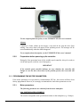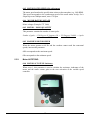
1
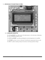
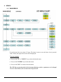
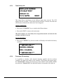
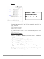
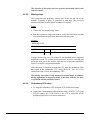
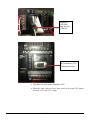
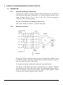
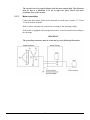
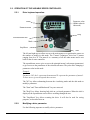
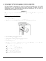
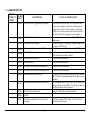
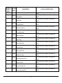
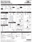
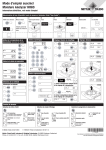
USER MANUAL CONTROL PANEL MECHANICAL ESCALATOR CJ1M PLC JEC-2000 & JEC-3000 SERIES CODE B44-07 JEC-2000 & JEC-3000 EN VERSION 07-1.6 TABLE OF CONTENTS 1. TEMPORARY START-UP: ................................................................................................................................................... 1-1 2. FINAL START-UP: ................................................................................................................................................................. 2-1 3. INTRODUCING THE MONITORING SCREEN: .............................................................................................................. 3-1 3.1. KEYBOARD OPERATION:............................................................................................................................................ 3-1 4. MENUS: .................................................................................................................................................................................... 4-1 4.1. MAIN MENUS:................................................................................................................................................................ 4-1 4.2. SUPERVISION MENU:................................................................................................................................................... 4-2 4.3. ALARM AND CPU I/O CHECKING: ............................................................................................................................. 4-3 4.3.1. Reset alarms: ........................................................................................................................................................ 4-3 4.3.2. Active fault list: ..................................................................................................................................................... 4-3 4.3.3. Fault history list: .................................................................................................................................................. 4-4 4.3.4. Processor I/O checking: ....................................................................................................................................... 4-4 4.4. REGISTERS ACCESS: .................................................................................................................................................... 4-7 4.5. ESCALATOR & LCD CONFIGURATION MENU: ....................................................................................................... 4-8 4.5.1. Escalator options:................................................................................................................................................. 4-8 4.5.1.1. 4.5.1.2. 4.5.1.3. 4.5.1.4. 4.5.1.5. 4.5.1.6. 4.5.1.7. 4.5.1.8. 4.5.1.9. Motor Protections: .................................................................................................................................................... 4-9 Start & Stop fine tuning (If with drive) : .................................................................................................................. 4-9 Protection & brake delay: ......................................................................................................................................... 4-9 Handrails monitoring: .............................................................................................................................................. 4-9 Steps monitoring: ................................................................................................................................................... 4-10 Reversal stop detection:.......................................................................................................................................... 4-10 Automatic oiler: ..................................................................................................................................................... 4-10 Buzzer: ................................................................................................................................................................... 4-11 Tandem operation:.................................................................................................................................................. 4-11 4.5.2. Handrail/steps setup: .......................................................................................................................................... 4-11 4.5.2.1. Handrail/steps setup: .............................................................................................................................................. 4-11 4.5.2.2. Missing steps: ......................................................................................................................................................... 4-12 4.5.2.3. Redundancy CPU setup :........................................................................................................................................ 4-12 4.5.3. Date and time: .................................................................................................................................................... 4-14 4.5.4. Language ............................................................................................................................................................ 4-14 4.5.5. LCD screen contrast: .......................................................................................................................................... 4-15 4.5.6. Create I/O table PLC: ........................................................................................................................................ 4-15 4.6. OPERATION COUNTER MENU: ................................................................................................................................ 4-15 4.7. PASSWORD MENU: ..................................................................................................................................................... 4-15 4.8. THE "ABOUT" MENU: ................................................................................................................................................. 4-16 5. CONTROL TECHNIQUES UNIDRIVE SP DRIVE START-UP: ..................................................................................... 5-1 5.1. CONNECTION: ............................................................................................................................................................... 5-1 5.1.1. Isolation transformer connections: ....................................................................................................................... 5-1 5.1.2. Encoder connection: ............................................................................................................................................. 5-1 5.1.3. Motor connection: ................................................................................................................................................ 5-2 5.2. OPERATION OF THE VARIABLE SPEED CONTROLLER: ....................................................................................... 5-3 5.2.1. Drive keyboard operation:.................................................................................................................................... 5-3 5.2.2. Modifying a drive parameter: ............................................................................................................................... 5-3 5.2.3. Save drive parameters: ......................................................................................................................................... 5-4 5.2.4. Accessing the error messages list: ........................................................................................................................ 5-5 5.2.5. Preparations before powering up the controller: ................................................................................................. 5-6 5.3. PROGRAMMING THE MOTOR PARAMETERS: ........................................................................................................ 5-6 5.3.1. Motor parameters: ................................................................................................................................................ 5-6 5.3.2. Motor AUTOTUNE: ............................................................................................................................................. 5-7 5.4. SPEED, ACCELERATION/DECELERATION PARAMETERS PROGRAMMING: ................................................... 5-8 5.4.1. Operational speeds programming: ....................................................................................................................... 5-8 5.4.2. Rounding factor (S-CURVES): ............................................................................................................................. 5-9 5.4.3. Accelerations and decelerations: .......................................................................................................................... 5-9 5.4.4. Slip Adjustment: .................................................................................................................................................. 5-10 5.5. SMARTCARD (0.30): .................................................................................................................................................... 5-10 5.5.1. Saving the smartcard: ......................................................................................................................................... 5-11 5.5.2. Changing the drive parameters from the smartcard: ......................................................................................... 5-12 6. REPLACEMENT OF THE PROGRAMMABLE CONTROLLER BATTERY:.............................................................. 6-1 7. ALARM DESCRIPTION: ....................................................................................................................................................... 7-1 NOTES AND PRECAUTIONS The escalator controller must be installed by trained and competent personnel; The controller power must come from a temporized switch fuse, not included in the controller. The fuse value must comply with the electrical code; It is necessary to install a conductor to ground the controller. Check the electrical code to find out the conductor size. An indirect duct grounding may cause intermittent troubles; To avoid problems caused by transportation and handling, check and tighten all the points of connections on the side "power"; from main power supply of the controller to the motor; Please note the controller warranty is valid one (1) year, starting on the billing day. An incorrect usage, a wrong connection or the disrespect of the user manual may void the warranty. Please note only the components are under warranty. Operating conditions: The 3 phases entry voltage may vary of more or less 10 %; A 60HZ frequency is standard, a 50HZ frequency is available on special order; Operating temperature: 0°C à 45°C; Do not install the NEMA 1 standard enclosure in a dusty environment or where there is risk of water infiltration. Other types of enclosures are available upon request (NEMA 4, 12 etc.); Relative humidity: 95% ; Communicate with Automatisation JRT inc. if the motor is more than 50ft away from the controller ; CSA approved. General information: The JEC-2000 & JEC-3000 controllers were designed for a quick installation and an easy operation. They include an internal diagnosis function, which simplifies the controller maintenance. Carefully read the user manual for a quick and safe installation. 1. TEMPORARY START-UP: A. Installing the inductive proximities: (refer to electrical schematics) Left and right handrails speed: There are two ways to install the inductive proximities to ensure an accurate speed calculation. Choose the option that is better fit for your escalator. Image #1: Use a full roll and machine in it a hole or a roll with a large enough hole so that the proximity sensor detects nothing when it is in line with the hole. The hole must be large enough to ensure the sensor does not detect anything for 0.2 sec or more at full speed. The controller calculates the time once the sensor stops detecting. Image #2: Install metal plates at equal distances from a symmetrical driving wheel. The controller starts calculating the time from the moment the sensor stops detecting. 1-1 Steps speed: Image #3: Install a PNP encoder that has only one 24 VDC output on the steps driving shaft. Once the escalator travels at nominal speed, the input frequency should be around 500 Hz. The speed calculation is carried out every tenth of a second. B. Installing the capacitive proximities: (refer to electrical schematics) Detecting missing steps: For optimum protection, install the capacitive proximities as close as possible to the combs. The controller evaluates the time between each pulse coming from the steps passing by the sensor. There may be 2 pulses per step. C. Connect all inputs required for proper functioning (refer to electrical schematics). D. Connect, when required, the CANbus communication (refer to electrical schematics). E. Connect power to the escalator controller. Controller at 208-460-600 volts without isolation transformer: Connect power to the controller directly at the L1, L2, and L3 from the main switch. Remove the 3 fuses and measure the voltage the first time. Controller at 208-460-600 volts with isolation transformer: Connect power to the drive provided with the controller using the isolation transformer by choosing the appropriate primary and secondary connections. The controller power must come from another circuit (refer to electrical schematics). Ground the XO terminal of the isolation transformer. Remove the 3 fuses and measure the voltage the first time. F. Connect the motor and the temperature sensor, if required (refer to electrical schematics). 1-2 Provide a copper conductor to ground the motor. G. Connect the brake (refer to electrical schematics). Provide a copper conductor to ground the brake. H. Turn on the controller power and measure: Controller supply voltage (refer to electrical schematics) 120 volts AC between "J" and "N". (refer to electrical schematics) 24 VDC between "+A" and "COM". (refer to electrical schematics) 24 VDC between "+DC" and "COM". (refer to electrical schematics) I. Green lights "POWER" and "RUN" should be activated on the controller. J. Carry out the drive start-up procedure, if required (see section 5). K. Connect the control remote on the escalator controller (Note: connect only one remote control at a time). L. Turn the inspection selector to the "INSP" position. M. Enter the following operation parameters using the LCD: • Low oil level (see section 4.5.1.1) • Start and stop adjustment (if a drive is used) (See section 4.5.1.2) • Brake (see section 4.5.1.3) • Handrail monitoring (see section 4.5.1.4) • Step monitoring (see section 4.5.1.5) • Reversal stop detection (see section 4.5.1.6) • Automatic oiler (see section 4.5.1.7) • Buzzer (see section 4.5.1.8) • Tandem operation (see section 4.5.1.9) • Date and time (see section 4.5.3) • Etc. N. Perform the proximities calibration (see section 4.5.2.1). 1-3 O. Perform the missing step detection adjustment (see section 4.5.2.2). P. Reset the controller and reset the alarm list using the LCD. Q. Check the operation of each connection. IMPORTANT The PLC inputs were designed to operate at 24 volts. DANGER: Do not apply 120VAC as it may cause severe damage to the PLC inputs. 1-4 2. FINAL START-UP: A. Follow the steps described in chapter 1. "TEMPORARY START-UP". B. "POWER" and "RUN" green lights on the controller must be activated. C. Disconnect the remote control and turn the inspection selector to the "NORM" position. D. Try to move the escalator in normal mode. Maintain the key turned about 0.5 second to start the escalator. E. In normal mode, activate each switch one at a time to ensure the escalator stops and that resets are carried out according to the specifications. F. Access the different menus and verify each parameter to finalize the controller adjustments. 2-1 3. INTRODUCING THE MONITORING SCREEN: 3.1. KEYBOARD OPERATION: The "UP and DOWN" keys allow access to the main menus or to the sub-menus. Furthermore, they allow changing the parameter values. The "LEFT and RIGHT" keys allow positioning the cursor on the parameter to be modified. The "ENTER" key allows access to a sub-menu. It also allows the registration of the new value. The "ESC" key allows returning to the previous menus or canceling a parameter change. 3-1 4. MENUS: 4.1. MAIN MENUS: For each menu, the access time is 2 hours. The timer is reset to zero each time a key is pressed. After 2 hours, the supervision screen will be displayed. To access a menu: Press on the "UP" or "DOWN" key to select the desired menu. Press on the "ENTER" key to select this menu. Press on the "ESC" to return to the main menu. The LCD has a protection that locks the menus allowing a value or parameter to be changed. To access these menus, the user must enter the password. 4-1 4.2. SUPERVISION MENU: This screen includes information about the current escalator state. IN UP DIRECTION L=0090 R=009 S=0090 PSO ACCO STP Presented information: Actual state of the escalator. L = Left handrail speed. R = Right handrail speed. S = Step and motor speed (if necessary). If a drive is used, the last line indicates the state of the signals sent to the drive. PSX = Preset speed X. PS0 = Preset speed 0 (see the drive section for more information). ACCX = Acceleration or deceleration X. ACC1 = Acceleration 1 (see the drive section for more information). FOW = Up direction (Forward). REV = Down direction (Reverse). STP = Stop. If a soft starter is used, the last line indicates the state of the soft starter. STOP = The escalator is not working. RUN = The escalator is working. UP TO SPEED = Nominal speed reached. If there is more than one status present in the PLC; the LCD will display each status at every second. 4-2 4.3. ALARM AND CPU I/O CHECKING: 4.3.1. Reset alarms: This menu allows resetting alarms that requires manual intervention. A status in the monitoring page is displayed when the controller requires a reset. If "NO ALARM" is displayed in the "ACTIVE FAULT LIST" and the escalator controller does not start, see the alarm history to know which alarm was activated. 4.3.2. Active fault list: This menu allows visualization of the alarms listed in the escalator controller. The LCD displays "NO ALARM" when the escalator controller has no more alarms listed. REPLACE OMRON CPU BATTERY HR8001 ENTER ->ERASE To erase the alarms: Press on the "ENTER" key, the following window will display a confirmation that the alarms have been erased. ***IMPORTANT*** ENTER->ERASE ESC->CANCEL ***IMPORTANT*** If an alarm is still present, it will be automatically displayed in the alarm list menu. Erasing the alarm in the LCD does not reset it in the escalator controller. 4-3 4.3.3. Fault history list: REPLACE OMRON CPU BATTERY 2009-07-13 10:12:22PM H8001 This menu allows visualization of the different alarms that occurred. The LCD displays the last 20 alarms. If the history already includes 20 alarms, the oldest one will be removed from the list when a new one is triggered. Alarms visualization: Press on the "UP/DOWN" key to visualize the different alarms Press on the "ESC" to return to the main menu. This menu displays, for each alarm, the correspondent number and also the time and date when they occurred. To erase the history: Press on the "ENTER" key, the next window will display and confirm the history is deleted. ***IMPORTANT*** ENTER->ERASE ESC->CANCEL ***IMPORTANT*** 4.3.4. Processor I/O checking: It is possible to visualize, with electrical drawings supplied with the escalator controller, the inputs and outputs of the controller. In the inputs and outputs pages, the "Channel CH" number is located on top of the module. If the module includes more than one "Channel CH" the underlined number corresponds to the right one. 4-4 Example: CH0000 = 0009 0000000000001001 15 ^ 8 4 0 This example indicates that "BIT 0" and "BIT 3" are activated. So, inputs "DOL" and "BDS" are activated. "BIT 0" is always on the right. "BIT15" is always on the left. The numbers 8, 4 and the symbol "^" are for information to help determine which "BIT" is active or not. Selecting the register number: Press on the "LEFT" or "RIGHT" key to place the cursor on the number to modify. Press on the "UP" or "DOWN" key to modify the number. Press on the "ENTER" key to save and go to the next menu. Press on the "ESC" key to go back to the previous menu. Press on the "UP" or "DOWN" key to see what is in the following or previous "CH". This diagnostic tool may also be used when you have the "CANbus" option. The "Channel CH" number is on the drawing. 4-5 Modules example "JRT-CAN-24IO": A "JRT-CAN-24IO" module has 24 inputs and 24 outputs. A "CH" has 16 "BIT". Input: CH 3131 bits 07-00 JRT-CAN-24IO #0 (07-00) CH 3131 bits 15-08 JRT-CAN-24IO #0 (15-08) CH 3132 bits 07-00 JRT-CAN-24IO #0 (23-16) CH 3132 bits 15-08 JRT-CAN-24IO #1 (07-00) CH 3133 bits 07-00 JRT-CAN-24IO #1 (15-08) CH 3133 bits 15-08 JRT-CAN-24IO #1 (23-16) 4-6 Output: CH 3802 bits 07-00 JRT-CAN-24IO #0 (07-00) CH 3802 bits 15-08 JRT-CAN-24IO #0 (15-08) CH 3803 bits 07-00 JRT-CAN-24IO #0 (23-16) CH 3803 bits 15-08 JRT-CAN-24IO #1 (07-00) CH 3804 bits 07-00 JRT-CAN-24IO #1 (15-08) CH 3804 bits 15-08 JRT-CAN-24IO #1 (23-16) 4.4. REGISTERS ACCESS: This menu allows reading and writing in one of the controller’s register. Choosing a register type: Press on the "UP" or "DOWN" keys to select a register. Press on the "ENTER" key to save. or Press on the "ESC" key to go back to the previous menu. Choice of registers: DM, CH, HR, LR and AR. (for "CQM1" PLC) DM, CH, HR and AR (for "CJ1M" PLC) Selecting the register number: Press on the "LEFT" or "RIGHT" keys to place the cursor on the number to modify. Press on the "UP" or "DOWN" key to modify the number. Press on the "ENTER" key to save and go to the next menu. Press on the "ESC" key to go back to the previous menu. Register value: The register value is shown under hexadecimal and binary formats. The "BIT 0" is always shown at right. The "BIT 15" is always shown at left. 4-7 Press on the "ESC" key to go back to the previous menu. Press on the "UP" or "DOWN" key for the following or previous register. Press on the "ENTER" key to modify the chosen register value. Press on the "ESC" key to return to the previous menu. Modification of the register value: Press on the "LEFT" or "RIGHT" key to position the cursor on the number to modify. Press on the "UP" or "DOWN" key to change the value of the register. Press on the "ENTER" key to confirm your choice and return to the previous menu and observe the new value. Press on the "ESC" key to return to the previous menu. 4.5. ESCALATOR & LCD CONFIGURATION MENU: 4.5.1. Escalator options: This menu offers different options to configure and adjust the escalator. The options are distributed in different sub-menus. Selection of an option: Press on the "UP" or "DOWN" key to select the desired option. Press the "ENTER" key. Press the "UP" or "DOWN" key to select the parameter to check. Press the "LEFT" or "RIGHT" key to edit the parameter. Press the "LEFT" or "RIGHT" key to change the digit to modify. Press the "UP" or "DOWN" key to change the number. Press the "ENTER" key to save the new value and exit edition mode. Press the "ESC" key to exit without saving. Repeat for all parameters that you want to change. 4-8 4.5.1.1. OPTION Motor Protections: DESCRIPTION UNIT ACTIVATE LOW OIL LEVEL Activation of the low oil level sequence YES/NO INVERT LOW OIL SENSOR CONTACT Inverting of the polarity for the low oil sensor YES/NO DELAY LOCK START IF BNH The low oil level does not provoke a stop on the escalator control. A message is displayed. However, if the escalator is on and the low oil level sensor is activated; after the specified delay, the escalator will not be able to restart. Resetting is required. minutes 4.5.1.2. OPTION BRAKE OPENING DELAY AT START DRIVE ENABLE OFF DELAY AT STOP 4.5.1.3. OPTION BRAKE PEAK VOLTAGE DELAY ACTIVATE BRAKE SWITCH MONITORING INVERT BRAKE SWITCH CONTACT ACTIVATE EMERGENCY BRAKE SWITCH MONITORING INVERT EMERGENCY BRAKE SWITCH CONTACT 4.5.1.4. OPTION VALUE Start & Stop fine tuning (If with drive) : DESCRIPTION Approximated brake open delay at start. After that delay, a speed command is given. Delay before turning off the drive when the brake is released at the floor (zero electrics). UNIT VALUE 0.1s 0.1s Protection & brake delay: DESCRIPTION Time before the reduction of voltage at brake release if equipped with an HLD relay. UNIT TYPE 0.1s Activation of the brake release "BRC". YES/NO Inverting of the brake switch monitoring contacts "BRC". YES/NO Activation of the emergency brake release "BRCU". YES/NO Inverting of emergency brake switch monitoring contacts "BRCU". YES/NO Handrails monitoring: DESCRIPTION UNIT ERROR % OF UNDER SPEED ALARM DELAY UNDER SPEED STOP DELAY UNDER SPEED Percentage of errors allowed before stopping the escalator on a reduced speed of the handrails. Delay before the audible alarm is activated on a reduced speed of the handrails. Delay before the escalator stops on a reduced speed of the handrails. 0.1s ERROR % OVER SPEED Percentage of error allowed before stopping the escalator on an over speed of the handrails. % 4-9 % 0.1s TYPE OPTION DESCRIPTION UNIT ALARM DELAY OVER SPEED Delay before the audible alarm is activated on an over speed of the handrails. 0.1s STOP DELAY OVER SPEED Delay before the escalator stops on an over speed of the handrails. 0.1s ALARM DELAY PROXIMITY LOSS Delay before the activation of the audible alarm when losing the proximity sensor. 0.1s STOP DELAY PROXIMITY LOSS Delay before the escalator stops after losing the proximity sensor. 0.1s 4.5.1.5. OPTION Steps monitoring: DESCRIPTION UNIT ERROR % OF UNDER SPEED Percentage of errors allowed before stopping the escalator on a reduced speed of the steps. % ALARM DELAY UNDER SPEED STOP DELAY UNDER SPEED Delay before the audible alarm is activated on a reduced speed of the steps. Delay before the escalator stops on a reduced speed of the steps. Percentage of error allowed before stopping the escalator on an over speed of the steps. Delay before the escalator stops on an over speed of the steps. ERROR % OVER SPEED STOP DELAY OVER SPEED 4.5.1.6. OPTION ACTIVATE THE MONITORING INVERT THE CONTACT DELAY BEFORE STOP IN UP DIRECTION DELAY BEFORE STOP IN DOWN DIRECTION 4.5.1.7. OPTION TYPE TYPE 0.1s 0.1s % 0.1s Reversal stop detection: DESCRIPTION Supervision activation of the direction reversal detection. Inverting of the direction reversal switch monitoring contacts. Delay before the escalator stops on a detection of an upward direction reversal. Delay before the escalator stops on a detection of a downward direction reversal. UNIT TYPE YES/NO YES/NO 0.1s %0.1s Automatic oiler: DESCRIPTION UNIT ACTIVATE AUTOMATIC OILER Automatic lubrication sequence activation. YES/NO FREQUENCE AUTOMATIC OILER Time between each lubrication. HOURS INJECTION TIME Duration of lubrication. AUTOMATIC OILER WITH PULSES Allows applying lubrication with pulses. 4-10 0.1s YES/NO TYPE OPTION DESCRIPTION UNIT PULSE ON DELAY Duration of the lubrication pulse. 0.1s PULSE OFF DELAY Off time between lubrication pulses. 0.1s 4.5.1.8. Buzzer: OPTION DESCRIPTION Alarm operation time. The audible alarm is on when detecting: under/over speed of the handrails or steps, loss of the handrails proximity sensors signal, activation of the up/down cover of the emergency stop, low oil level and controller battery low tension. ALARM TIME 4.5.1.9. UNIT TYPE 0.1s Tandem operation: OPTION DESCRIPTION UNIT ACTIVATE THE TANDEM OPERATION Tandem operation activation. YES/NO TOP ESCALATOR Determines if the escalator is the upper or lower escalator (YES = Upper). YES/NO 4.5.2. TYPE TYPE Handrail/steps setup: 4.5.2.1. Handrail/steps setup: The calibration of the handrails allows determination of the correct number of counts so that the actual handrails calculated speed is equal to the rated speed of the escalator. The actual speed is automatically updated when a count number has been modified. Setup: Choose the "Left handrail" menu. Run the escalator in inspection mode to check the calculated speed with the current base count, which is entered into the controller. Modify the base count until the actual displayed speed corresponds to the nominal speed of the escalator. Repeat for the other handrail and the speed sensor of the steps and/or the motor if installed. Once the setup is complete in the main CPU, note the parameters value and repeat in the redundancy CPU using the LCD. See 4.5.2.3 for connection of the LCD to the redundancy CPU. 4-11 The detection of the under and over speed are deactivated when in the inspection mode. 4.5.2.2. Missing steps: The system has two proximity sensors (one at the top and one at the bottom). Typically, a pulse is generated at each step. The processor calculates the time between pulses in tenths of a second. Setup: Choose the "top step missing" menu. Run the escalator in inspection mode to verify the actual time in tenths of a second between each steps detected by the processor. Example: MISSING STEP 0016 (represents the observed timer total) ACTUAL = xx Timer total x 2 = 3.2 sec NEW = xx Timer total x 2 = 3.2 sec A step is observed at every 1.6 second. So the threshold before triggering should not exceed 3.2 seconds for the processor to detect a missing step before the hole gets to the surface. Take the sum of the timer and add at least 0.5 second as a triggering threshold. Once the setup is complete in the main CPU, note the parameters value and repeat in the redundancy CPU using the LCD. See 4.5.2.3 for connection of the LCD to the redundancy CPU. The missing step option is only activated in normal mode. In addition, during adjustments in inspection mode, if the timer indicates 99, there is a problem with the proximity sensors. 4.5.2.3. Redundancy CPU setup : To setup the redundancy CPU using the LCD, follow these steps: Unplug the communication cable from the main CJ1M PLC LCD (port 232) or remove the CS1W-CN118 if the LCD is connected on the peripheral port (refer to electrical schematics). 4-12 Unplug the LCD cable from the main CJ1M PLC. Plug the LCD cable on the rendundancy CPU communication port. Plug the LCD cable on the redundancy CPU. Enter the same values as have been saved in the main CPU during sections 4.5.2.1 and 4.5.2.2 setup. 4-13 4.5.3. Date and time: This menu allows you to view and modify the LCD internal clock. Modification: Press on the "ENTER" key to access the modification window. Press on the "LEFT" or "RIGHT" key to position the cursor on the digit to modify. Press on the "UP" or "DOWN" key to modify the selected digit. Press on the "ENTER" key to confirm your changes. or Press on the "ESC" key to cancel the changes and return to the previous menu. The LCD is fitted with a lithium battery that keeps the clock and date current when the LCD is unpowered. Format: Date = YYYY-MM-DD-dd (year – Month – Day - day of the week) AAAA = 2000 to…. MM = 1 – 12 DD = 1 – 31 dd = 0 – 6 (0 = Sunday) Hour = HH – MM – SS (Hour – Minute – Second) H = 0 – 23 M = 0 – 59 S = 0 – 59 4.5.4. Language This menu allows you to select the language. For French: Press on the "UP" key. 4-14 For English: Press on the "DOWN" key. or Press on the "ESC" key. 4.5.5. LCD screen contrast: This menu allows you to adjust the LCD contrast. Contrast adjustment: Press on the "UP" or "DOWN" key to modify the contrast. Press on the "ENTER" key to confirm your new setting. or Press on the "ESC" key to return to the previous menu. 4.5.6. Create I/O table PLC: This menu allows adjusting the modules input and output table. In the case of the CJIM controller, when adding a new module the table must be re-created so that the CPU recognizes the new module. To perform this command, the escalator must be stopped and in inspection mode. Input/output table creation: Press on the "ENTER" key to create the table. or Press on the "ESC" key to return to the previous menu. 4.6. OPERATION COUNTER MENU: This menu allows viewing some statistics compiled by the escalator controller. Operation time. Number of upward starts. Number of downward starts. 4.7. PASSWORD MENU: This menu provides the ability to lock or unlock the LCD. Moreover, it is possible to change the current password with a new one. If the LCD is locked, it is possible to see all menus; however 4-15 the work "LOCKED" will be displayed when accessing menus and changes to values will be denied. Entering the password: PASSWORD: 0000 Press on the "LEFT" or "RIGHT" key to position the cursor on the desired digit. Press on the "UP" or "DOWN" key to modify the password digit. Press on the "ENTER" key to confirm your changes. or Press on the "ESC" key to return to the previous menu. 4.8. THE "ABOUT" MENU: This menu indicates the LCD version. Press on the "ESC" key to return to the previous menu. 4-16 5. CONTROL TECHNIQUES UNIDRIVE SP DRIVE START-UP: 5.1. CONNECTION: 5.1.1. Isolation transformer connections: If the escalator controller is equipped with an isolation transformer, the variable drive controller input voltage must be maintained 5 to 10 volts around the controller's rated voltage. Example: 450 to 470 for a drive of 460 volts. Choose the appropriate connections at the transformer primary. The "X0" terminal must be grounded for safety reasons. Refer to the schematic in section 5.1.3. (Motor connection). 5.1.2. Encoder connection: The encoder comprises a plastic insulator to protect the ball against feedback caused by PWM drive types. The plastic mounting bracket should be moderately tight and must allow lateral movement of the encoder. We strongly recommend mechanically isolating the motor shaft encoder. The encoder’s multi-strand cable must be placed alone in a conduit to eliminate electrical interference from other tension cables. This conduit must include a built-in shield. This shield is connected to the escalator controller "SHD" terminal. Connect as shown on the schematic supplied with the controller. 5-1 The encoder has to be properly aligned with the motor output shaft. The vibrations must be kept to a minimum so as not to affect the speed control and cause premature wear of the encoder. 5.1.3. Motor connection: Connect the three motor phases on the terminals or on the power switch, T1, T2 and T3 on the control enclosure. Refer to motor nameplate for connections according to the operating voltage. If the motor is equipped with a temperature switch, it must be connected according to the drawings. IMPORTANT The grounding conductors must be connected as per the following illustration: 5-2 5.2. OPERATION OF THE VARIABLE SPEED CONTROLLER: 5.2.1. Drive keyboard operation: Status █████████ █ ███ █ ████████ ██ █ █ ██ ██ █████████ ██ ███ Parameter name Parameter value (Blinks when in edit mode) Help Forward/Backwards Mode Stop/Reset Start The left and right arrows allow access to the main menus or to position the cursor on the number to modify in edit mode. The "Control Techniques" drive has 23 menus ranging from 0 to 22. The menu 0 is a summary of all the other menus and it was built for the elevator controller. The up and down arrows give access to the principal menus’ sub-menus (parameters) or give access to the parameters of the selected sub-menu. They also allow changing a parameter value in edit mode. Example: Parameter 3.02, the 3 represents the menu and 02 represent the parameter of menu 3. To have access, press the up and down arrows. The "M" key allows alternating between the visualizing mode and the edit mode to modify a parameter. The "Start" and "Forward/Backwards" keys are not used. The "Help" key allows showing help info on a selected parameter. When the info is displayed, the up and down arrows allows scrolling through the text. The "Stop/Reset" key allows resetting the drive. It will also be used for saving purposes, as describes later on. 5.2.2. Modifying a drive parameter: Use the following sequence to modify a drive parameter: 5-3 Use the left and right arrows to find the desired menu (example "0"). Use the up and down arrows to find the parameter to modify (example "0.45") and press the "M" key to switch to edit mode. The parameter value must be blinking. Press again on the "M" key to exit the Edit mode without saving changes. When the parameter to be modified contains several options, use the up and down arrows to select an option (example "SC.EnDat"). If the parameter is a numeric value, use the left and right arrows to position the cursor on the number to modify (example "0070") and use the up and down arrows to change the value. Once the value is correct, press the "Mode" key to save the new value and exit the Edit mode. 5.2.3. Save drive parameters: Do the following sequence to permanently save the values: Enter 1000 in the parameter 0.00: 0.00 1000 Frequency reference Using the left and right arrows, find the menu "0.yy"; Using the up and down arrows, find the parameter "0.00" and press "M" to enter the Edit mode. Using the left and right arrows, place the cursor on the number to modify. Using the up and down arrows, change the value of the number and enter 1000. Press "M" to save the modifications and exit the Edit mode. Press the red "Stop/Reset" button. The value 1000 becomes 0 and the parameters are saved. 5-4 5.2.4. Accessing the error messages list: The "UNIDRIVE SP" variable speed drive indicates two classes of events: faults and alarms. Faults: When a fault occurs, the drive stops and the brake drops. The screen light will blink. The word "Trip" will appear in the top left corner of the screen and the fault will appear in the screen top right corner. The fault description will appear in the bottom lines of the screen. To erase faults: Faults must be corrected before being erased from the drive’s memory. Once they are corrected press red "Stop Reset" button. Trip EnC2 Brake's encoder wire trip The content of parameters 10.20 to 10.29 indicates the 10 latest faults, 10.20 being the last one to have occured. 5-5 To visualize the faults: 10.21 EnC2 Trip 1 For the complete fault description, see the UNIDRIVE SP drive user’s manual. Alarms: Contrarily to faults, alarms do not trigger a stop and do not stop the drive from starting. Any active alarm will appear on the operating screen. The message will be erased automatically when the alarm disappears. For a complete alarm description, see the UNIDRIVE SP drive user’s manual. 5.2.5. Preparations before powering up the controller: During the first operational tests of the variable speed controller, always be ready to cut the main power switch in case of emergency. IMPORTANT If the variable speed controller indicates an error situation, the controller will attempt to reset the drive three times. If the problem persists, the reset trials will stop. 5.3. PROGRAMMING THE MOTOR PARAMETERS: If the motor parameters were provided to Automatisation JRT Inc., this section will have been factory programmed. However, it is strongly recommended to check these parameters on site. 5.3.1. Motor parameters: The following parameters are obtained from the motor nameplate. 0.46 MOTOR RATED CURRENT The current corresponds to the specification written on the nameplate (e.g. 18 amps). 5-6 0.45 MOTOR RATED SPEED (Slip adjustment) The motor speed matches the specification written on the nameplate (e.g. 1800 RPM). This speed corresponds to the synchronous speed of the motor minus its slip. For a 50rpm slip on an 1800rpm motor, enter 1750 rpm. 0.44 MOTOR RATED VOLTAGE Motor voltage: (Example: 575 Volts). 0.42 MOTOR – POLES QUANTITY This parameter contains the number of motor poles. Number of poles = 120 Degrees X frequency Hz = 120 Degrees X 60Hz = 4 poles motor RPM 1800 0.02 MAXIMUM MOTOR SPEED When the motor operates at 60 Hz and the escalator cannot reach the contractual speeds, increase this parameter. 60Hz corresponds to the maximum speed. 0Hz corresponds to the minimum speed. 5.3.2. Motor AUTOTUNE: 0.40 MOTOR AUTOTUNE Stationary When set to 1, this parameter is used to calculate the resistance, inductance of the motor and the motor current gains at the next activation of the variable speed controller. 0.40 Autotune 5-7 1 Using the LCD, note the controller’s DM0049 parameter value and increase it to 500. Put 1 in drive parameter 0.40. Place the escalator in "Inspection" mode. Activate the escalator in upward or downward direction using the remote until parameter 0.40 indicates 0. The motor will not be turning during the AUTOTUNE. The tuning is now complete. The values will be updated in 0.36, 0.37, 0.38 and 0.39. Restore parameter DM0049 to its previously noted value. Save the drive's parameters. 5.4. SPEED, ACCELERATION/DECELERATION PARAMETERS PROGRAMMING: 5.4.1. Operational speeds programming: 60Hz corresponds to the contractual speed. Find the value to be entered using a rule of 3. Parameter 0.20 Description Preset ref 1: Zero Value to enter Controller output 0 Hz No outputs 20 Hz PS1 = Activated 30 Hz PS2 = Activated 60 Hz PS1 and PS2 = Activated electrics 0.21 Preset ref 2: Economical speed 0.22 Preset ref 3: Inspection speed 0.23 Preset ref 4: Contractual speed Connect all necessary inputs to allow the escalator to be opened in inspection mode. The "PS2" inspection speed is set to 30 Hz at the factory. Try to move the escalator in inspection mode and measure the actual speed in ft/min with a tachometer. The ft/min/Hz relation has to be determined: Example: Speed measured with a tachometer = 45ft/min. Desired speed = 50 ft/min. Variable speed controller output frequency = 30 Hz We now know the conversion factor: 5-8 30Hz * 50 ft/min = 33.3 Hz enter this value in "PS2" 45fti/min Save the parameters at the end of the adjustments. 5.4.2. Rounding factor (S-CURVES): The rounding factor allows a transition between 2 speeds. Adjust according to the table below: Parameter Description Value to enter 0.28 2 s²/1000RPM: Generally between 1 and 4 by each S ramp acceleration limit 0.25 or 0.5 increment, depending on the desired comfort. The higher the value, the more the rounding factor is accentuated, the smoother the acceleration and deceleration will be. However, the acceleration and deceleration distances will be longer. 5.4.3. Accelerations and decelerations: It is essential that all speeds be well programmed before adjusting the accelerations and the decelerations. The accelerations and decelerations parameter units are in sec/100 Hz. Adjust the accelerations and decelerations according to the table below: Parameter Description Value to enter 0.03 Acceleration rate 1: Not used 0.04 Deceleration rate 1: Not used 0.16 Acceleration rate 2: For Inspection speed = 30Hz inspection speed Desired Acc/Dec = 0-30Hz in 4 sec 4Sec 100 Hz 13.33s / 100 Hz 30 Hz 0.17 Deceleration rate 2: For Inspection speed = 30Hz inspection speed Desired Acc/Dec = 0-30Hz in 0.5sec 0,5Sec 100 Hz 1.66s / 100 Hz 30 Hz 0.18 Acceleration rate: For contractual Inspection speed = 60Hz speed Desired Acc/Dec = 0-60Hz in 20sec 20Sec 100 Hz 33.33s / 100 Hz 60 Hz 5-9 0.19 Deceleration rate 3: For See parameter 0.18 example contractual speed 5.4.4. Slip Adjustment: 0.48 MOTOR RATED SPEED (Slip adjustment) Indicates the synchronous speed of the motor minus the motor slip. This value is generally between 1 and 3 percent of the synchronous speed. New motors: Enter the value found on the identification plate. Example: 1175 RPM for a 6 poles motor (slip of 25RPM). Old motors 1 or 2 AC speed with or without encoder: These motors have a high slip and often have 1200 RPM registered on the identification plate. This value is generally between 3 and 10 percent of the synchronous speed. Example: 1200 – (1200Rpm X 5%) = 1140 RPM Motor Rated Speed = 1140 RPM to start the trials. If the programmed slip frequency value does not correspond to the motor, it will not sufficiently develop the required torque to move the escalator in upward or downward direction at low speed with a full charge. 0.43 POWERS RATED FACTOR This parameter corresponds to the motor torque factor, the down phasing between the motor tension and current. The default value is 0.85. However, on certain old motors, if it does not follow instructions or if it is not constant, reduce the value by increments of 0.02. This value must be between 0.60 and 0.85. 5.5. SMARTCARD (0.30): There is a smart card behind the Unidrive SP drive’s operator screen. It allows, among other things, copying data from one drive to the other. This saves time and avoids forgetting parameters. Once the first escalator is adjusted, the card allows transfering all of the modified parameters to the other drives. It is, however, necessary to carry out again the Autotune, since some parameters may differ. 5-10 If the data copy of one escalator to another is done after the "Autotune", take note of the parameters "0.36, 0.37 0.38" and "0.39" (current gain), copy the data and restore the original values of those 3 parameters. 5.5.1. Saving the smartcard: 0.30 Prog Smartcard Param. cloning Use the left and right arrows to find the menu "0.yy". Use the up and down arrows to find the parameter "0.30" and press "M" to enter the edit mode. Use the up and down arrows to select "Prog". Press "M" to save the new value and exit the edit mode. Press the red button "Stop/Reset", the word "Prog" becomes "None" and the parameters are saved in the smartcard. (The letters CC will blink during access to the card). 5-11 5.5.2. Changing the drive parameters from the smartcard: 0.30 Read Smartcard Param. cloning Use the left and right arrows to find the menu "0.yy". Use the up and down arrows to find the parameter "0.30" and press "M" to enter the edit mode. Use the up and down arrows to select "Read". Press "M" to save the new value and exit the edit mode. Press the red button "Stop/Reset", the word "Read" becomes "None" and the parameters are saved in the smartcard. (The letters CC will blink during access to the card). For more explanation on the smartcard, go to the parameter "0.30" in the drive manual. 5-12 6. REPLACEMENT OF THE PROGRAMMABLE CONTROLLER BATTERY: The battery lifetime is approximately five years. If the voltage level becomes too low, the ALARM indicator on the PLC will flash and the car will be turned "out of order". The battery must then be replaced within one week. Replacement dates of the battery are indicated on the CPU front cover. The catalogue number for the battery is CJ1W-BAT01. IMPORTANT The new battery must be installed within 5 minutes after removing the old one to preserve the program. Follow these steps to replace the battery: Turn off the main power. Open the cover above the peripheral port on the CPU. The battery can now be seen. Pull out the battery and unplug its connector. Quickly put the new battery in place and plug the connector. Turn the main power on. Though it is not mandatory, the "low battery" message in the CPU should be erased. If a "low battery" alarm is active, it must be cleared. Connect the handheld programmer; Type in the password CLR-MONTR-CLR; The screen will display "low batt"; Type in CLR-FUN-MONTR-MONTR. 6-1 Make sure that POWER and RUN indicators on the CPU are on. The escalator may then be put back into service. 6-2 7. ALARM DESCRIPTION: WITH OR WITHOUT RESET: ALARM CODE: DESCRIPTION: CAUSES & VERIFICATIONS 0 HR80.00 The low oil level is triggered or not triggered. 1 HR80.01 The PLC battery must be replaced. 0 HR80.02 Phase reverse/lost detection 1 0 HR80.03 Motor overload detection by the "RS1" relay. HR80.04 24 Volts DC +A power failure. 0 HR80.05 The latch does not activate. Verify protection fuse. The filament could be defective. There may have been short-circuited. Verify the latch functionality 1 HR80.06 The latch is stuck. Verify the latch functionality 1 HR80.07 Direction reversal detected while going up. Verify the switch functionality 1 1 HR80.08 Direction reversal detected while going down. HR80.09 The brake does not open properly. 1 HR80.10 The emergency brake does not open properly. 1 HR80.11 The "ML" brake malfunction. Verify the switch functionality The brake does not pick up according the brake contact (BRC). Check the mechanical brake and the brake switch operation. The emergency brake does not pick up according the emergency brake contact (BRCU). Check the mechanical brake and the brake switch operation. Verify the "ML" brake switch functionality. 0 HR80.12 SPARE 0 HR80.13 Drive RUN signal did not come on at a start command. 7-1 Verify the oil level in the tank. The low oil level does not cause the controller to shut down. The message is logged in the event list. If the escalator is operational and the low oil switch activates, after the user-specified time the escalator will no longer turn on if stopped. See section 6 of user’s manual for the PLC battery replacement. Verify the controller’s main input voltage, the supply and the contact of "RPR" relay. Verify the state and/or the adjustment of the "RS1" relay. Verify the controller "MA" output. Verify if the drive received the start function. WITH OR WITHOUT RESET: ALARM CODE: DESCRIPTION: CAUSES & VERIFICATIONS 0 HR80.14 Drive fault. 0 HR80.15 The actual speed does not follow the internal drive speed "Speed deviation low". Refer to section 5 to access alarms list. Verify RDY signal condition, it should be activated. Compare the encoder rotation direction to the motor's. Verify the motor adjustment parameters. 1 HR81.00 Under speed left handrail. Verify the left handrail proximity sensor functionality. 1 HR81.01 Over speed left handrail. Verify the left handrail proximity sensor functionality. 1 HR81.02 Under speed right handrail. Verify the right handrail proximity sensor functionality. 1 HR81.03 Over speed right handrail. Verify the right handrail proximity sensor functionality 1 HR81.04 Step under speed detection Verify the proximity sensor functionality or the escalator encoder. 1 HR81.05 Step over speed detection Verify the proximity sensor functionality or the escalator encoder 1 HR81.06 Left handrail proximity sensor signal loss Verify the functionality of the left handrail proximity. 1 HR81.07 Right handrail proximity sensor signal loss Verify the functionality of the right handrail proximity 1 HR81.08 Proximity sensor or encoder signal loss Verify the functionality of the escalator encoder or the proximity. 1 HR81.09 Top sensor missing step detection Verify the functionality of the top missing step proximity 1 HR81.10 Top sensor missing step detection Verify the functionality of the top missing step proximity 1 HR81.11 Tandem escalator stop If bottom escalator = Stops if the top escalator stops while going upward. If top escalator = Stops if the bottom escalator stops while going downward. The escalator will stop if the adjacent escalator stops. 0 HR81.12 SPARE HR81.13 SPARE 0 7-2 WITH OR WITHOUT RESET: ALARM CODE: DESCRIPTION: CAUSES & VERIFICATIONS 0 HR81.14 SP (safety processor) relay output did not active. The CP1L processor output (SP) did not open. Turn off the power and check the output with a meter. 0 HR81.15 SP (safety processor) relay output remained closed. The CP1L processor output (SP) remained closed. Turn off the power and check the output with a meter. 1 HR82.00 Refer to the electrical schematics to determine the switch. Refer to the electrical schematics to determine the switch. Refer to the electrical schematics to determine the switch. Refer to the electrical schematics to determine the switch. Refer to the electrical schematics to determine the switch. Refer to the electrical schematics to determine the switch. Refer to the electrical schematics to determine the switch. Refer to the electrical schematics to determine the switch. Refer to the electrical schematics to determine the switch. Refer to the electrical schematics to determine the switch. Refer to the electrical schematics to determine the switch. Refer to the electrical schematics to determine the switch. Refer to the electrical schematics to determine the switch. Vertical bottom right comb. 1 HR82.01 0 HR82.02 0 HR82.03 1 HR82.04 1 HR82.05 0 HR82.06 0 HR82.07 1 HR82.08 Horizontal bottom right comb. Bottom stop switch in machinery. Bottom emergency stop. Horizontal top left comb. Vertical top left comb. Top stop switch in machinery. Top emergency stop. Right step broken chain 1 HR82.09 0 HR82.10 0 HR82.11 1 HR82.12 Bottom step sag Bottom stop key/button Bottom left access switch Left step broken chain 7-3 WITH OR WITHOUT RESET: ALARM CODE: 0 HR82.13 1 HR82.14 1 HR82.15 1 HR83.00 0 HR83.01 0 HR83.02 0 0 1 0 DESCRIPTION: CAUSES & VERIFICATIONS Bottom right uptrust 2 Refer to the electrical schematics to determine the switch. Refer to the electrical schematics to determine the switch. Refer to the electrical schematics to determine the switch. Refer to the electrical schematics to determine the switch. Refer to the electrical schematics to determine the switch. Refer to the electrical schematics to determine the switch. Bottom left skirt 1 Refer to the electrical schematics to determine the switch. Bottom left skirt 2 Refer to the electrical schematics to determine the switch. Bottom right handrail Refer to the electrical schematics to determine the switch. Bottom right access switch Vertical bottom left comb Horizontal bottom left comb Bottom left handrail Bottom left uptrust 1 HR83.03 HR83.04 HR83.05 HR83.06 Refer to the electrical schematics to determine the switch. Refer to the electrical schematics to determine the switch. Refer to the electrical schematics to determine the switch. Refer to the electrical schematics to determine the switch. Refer to the electrical schematics to determine the switch. Refer to the electrical schematics to determine the Bottom right skirt 1 0 HR83.07 0 HR83.08 0 HR83.09 1 HR83.10 1 HR83.11 Horizontal top right comb Bottom right skirt 2 Top left access switch Top right access switch Vertical top right comb 7-4 WITH OR WITHOUT RESET: ALARM CODE: 0 HR83.12 0 HR83.13 1 HR83.14 0 HR83.15 1 HR84.00 1 HR84.01 1 HR84.02 0 HR84.03 1 HR84.04 0 HR84.05 1 HR84.06 1 HR84.07 0 HR84.08 0 HR84.09 0 HR84.10 DESCRIPTION: CAUSES & VERIFICATIONS switch. Refer to the electrical schematics to determine the switch. Refer to the electrical schematics to determine the switch. Refer to the electrical schematics to determine the switch. Refer to the electrical schematics to determine the switch. Refer to the electrical schematics to determine the switch. Refer to the electrical schematics to determine the switch. Refer to the electrical schematics to determine the switch. Refer to the electrical schematics to determine the switch. Refer to the electrical schematics to determine the switch. Refer to the electrical schematics to determine the switch. Refer to the electrical schematics to determine the switch. Refer to the electrical schematics to determine the switch. Refer to the electrical schematics to determine the switch. Refer to the electrical schematics to determine the switch. Refer to the electrical schematics to determine the switch. Top right skirt Top left skirt Top right handrail Right step obstruction Over speed governor Motor temperature Top step sag Top stop key/button Top left handrail Left step obstruction Broken drive chain. Disconnected motor safety Egress restriction Top cover button LID Bottom cover button LID 7-5 WITH OR WITHOUT RESET: ALARM CODE: 0 HR84.11 0 HR84.12 SPARE 0 HR84.13 SPARE 0 HR84.14 SPARE 0 HR84.15 SPARE 1 HR85.00 The "MAN" relay was not activated. Verify the "MAN" relay functionality; it was not activated when the controller "MAN" input was activated. 1 HR85.01 The "MAN" relay contacts remained closed. Verify the "MAN" relay functionality, it remained closed when the controller "MAN" input deactivated. 1 HR85.02 The "CM1" relay was not activated Verify the "CM1" relay functionality; it was not activated when the controller "CM1" input was activated. 1 HR85.03 The"CM1" relay contacts remained closed. Verify the "MAN" relay functionality; it remained closed when the controller "MAN" input deactivated 1 HR85.04 The "CM2 was not activated. Verify the "CM2" relay functionality; it was not activated when the controller "CM2" input was activated. 1 HR85.05 The "CM2" relay contacts remained closed. Verify the "CM2" relay functionality; it remained closed when the controller "CM2" input deactivated 1 HR85.06 The "SEC" was not activated. Verify the "SEC" relay functionality; it was not activated when the controller "SEC" input was activated 1 HR85.07 The "SEC" relay contacts remained closed. Verify the "SEC" relay functionality; it remained closed when the controller "SEC" input deactivated 1 HR85.08 The "RSEC" relay was not activated. Verify the "RSEC" relay functionality; it was not activated when the controller "RSEC" input was activated. DESCRIPTION: CAUSES & VERIFICATIONS Refer to the electrical schematics to determine the switch. Wheel cover switch 7-6 WITH OR WITHOUT RESET: ALARM CODE: DESCRIPTION: CAUSES & VERIFICATIONS 1 HR85.09 The "RSEC" relay contacts remained closed. Verify the "RSEC" relay functionality; it remained closed when the controller "RSEC" input deactivated. 1 HR85.10 The "RA" relay contacts remained closed. Verify the "RA" relay; it has remained closed even if a switch has opened in its safety line. 1 HR85.11 The "RB" relay contacts remained closed Verify the "RB" relay; it has remained closed even if a switch has opened in its safety line. 1 HR85.12 The "RC" relay contacts remained closed Verify the "RC" relay; it has remained closed even if a switch has opened in its safety line. 1 HR85.13 The "RD" relay contacts remained closed Verify the "RD" relay; it has remained closed even if a switch has opened in its safety line. 1 HR85.14 The "RE" relay contacts remained closed Verify the "RE" relay; it has remained closed even if a switch has opened in its safety line. 1 HR85.15 SPARE 1 HR86.00 The "R5" relay was not activated Verify the "R5" relay functionality; it was not activated when the controller "R5" input was activated. 1 HR86.01 The "R5" relay contacts remained closed. Verify the "R5" relay functionality; it remained closed when the controller "R5" input deactivated. 1 HR86.02 The "B/B1" relay was not activated Verify the "B/B1" relay functionality; it was not activated when the controller "B/B1" input was activated. 1 HR86.03 The "B/B1" relay contacts remained closed Verify the "B/B1" relay functionality; it remained closed when the controller "B/B1" input deactivated. 1 HR86.04 UC or UDC contactor did not activate. Verify the "UD" or "UDC" relay functionality; it was not activated when the controller "UD" or "UDC" input was activated. 1 HR86.05 UC or UDC contactor has remained closed. Verify the "UC" or "UDC" relay functionality; it 7-7 WITH OR WITHOUT RESET: ALARM CODE: DESCRIPTION: CAUSES & VERIFICATIONS remained closed when the controller "UC" or "UDC" input deactivated. 1 HR86.06 DC contactor did not activate. Verify the "DC" relay functionality; it was not activated when the controller "DC" input was activated. 1 HR86.07 DC contactor has remained closed. Verify the "DC" relay functionality; it remained closed when the controller "DC" input deactivated. 1 HR86.08 C2 contactor did not activate. Verify the "C2" relay functionality; it was not activated when the controller "C2" input was activated. 1 HR86.09 C2 contactor has remained closed. Verify the "C2" relay functionality; it remained closed when the controller "C2" input deactivated. 1 HR86.10 C3 contactor did not activate. Verify the "C3" relay functionality; it was not activated when the controller "C3" input was activated. 1 HR86.11 C3 contactor has remained closed. Verify the "C3" relay functionality; it remained closed when the controller "C3" input deactivated 1 HR86.12 ML contactor did not activate. Verify the "ML" relay functionality; it was not activated when the controller "ML" input was activated. 1 HR86.13 ML contactor has remained closed. Verify the "ML" relay functionality; it remained closed when the controller "ML" input deactivated. 0 HR86.14 SPARE 0 HR86.15 SPARE 1 HR87.00 The "RUN1" relay was not activated. Verify the "RUN1" relay functionality; it was not activated when the controller "RUN1" input was activated. 1 HR87.01 The "RUN1" relay was not activated. Verify the "RUN1" relay functionality; it was not activated when the controller "RUN1" input was activated. 7-8 WITH OR WITHOUT RESET: ALARM CODE: DESCRIPTION: CAUSES & VERIFICATIONS 1 HR87.02 The "RUN2" relay contacts remained closed. Verify the "RUN2" relay functionality; it was not activated when the controller ""RUN2" input was activated. 1 HR87.03 The "RUN2" relay contacts remained closed. Verify the "RUN2" relay functionality; it remained closed when the controller "RUN2" input deactivated. 1 HR87.04 The "UPDW" was not activated. Verify the "UPDW" relay functionality; it was not activated when the controller "UPDW" input was activated. 1 HR87.05 The "UPDW" relay contacts remained closed. Verify the "UPDW" relay functionality; it remained closed when the controller "UPDW" input deactivated. 1 HR87.06 The "SSR1" was not activated. Verify the "SSR1" relay functionality; it was not activated when the controller "SSR1" input was activated. 1 HR87.07 The "SSR1" relay contacts remained closed. Verify the "SSR1" relay functionality; it remained closed when the controller "SSR1" input deactivated. 1 HR87.08 The "SSR2" was not activated. Verify the "SSR2" relay functionality; it was not activated when the controller "SSR2" input was activated. 1 HR87.09 The "SSR2" relay contacts remained closed. Verify the "SSR2" relay functionality; it remained closed when the controller "SSR2" input deactivated. 1 HR87.10 Top step missing signal remained closed. Verify the top missing step proximity functionality. 1 HR87.11 Bottom step missing signal remained closed. Verify the bottom missing step proximity functionality. 1 HR87.12 The relays "RA" to "RE" contacts remained closed on start. Verify the "RA" to "RE" relays functionality. They remained closed when the controller RAE" input deactivated. 1 HR87.13 Redundancy CPU fault. Connect the CPU on the redundancy CPU to access the 7-9 WITH OR WITHOUT RESET: ALARM CODE: DESCRIPTION: CAUSES & VERIFICATIONS alarms. See section 4.5.2.3 for LCD connection. 1 1 HR87.14 SPARE HR87.15 SPARE 1 HR88.00 Loss of communication with JRT-CAN-24IO module 0 Verify the switch connections, the electrical power and configuration (See manual CANBUS) 1 HR88.01 Loss of communication with JRT-CAN-24IO module 1 Verify the switch connections, the electrical power and configuration (See manual CANBUS) 1 HR88.02 Loss of communication with JRT-CAN-24IO module 2 Verify the switch connections, the electrical power and configuration (See manual CANBUS) 1 HR88.03 Loss of communication with JRT-CAN-24IO module 3 Verify the switch connections, the electrical power and configuration (See manual CANBUS) 1 HR88.04 Loss of communication with JRT-CAN-MAS Verify the switch connections, the electrical power and configuration (See manual CANBUS) 0 HR88.05 SPARE HR88.06 SPARE 0 0 0 0 0 0 0 0 0 HR88.07 SPARE HR88.08 SPARE HR88.09 SPARE HR88.10 SPARE HR88.11 SPARE HR88.12 SPARE HR88.13 SPARE HR88.14 SPARE 7-10 WITH OR WITHOUT RESET: 0 ALARM CODE: DESCRIPTION: CAUSES & VERIFICATIONS HR88.15 SPARE 7-11