1
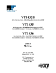
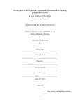
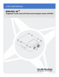
LORD USER MANUAL
IEPE-Link™ -LXRS®
Wireless IEPE Sensor Node
© 2014 LORD Corporation
MicroStrain® Sensing Systems
459 Hurricane Lane
Suite 102
Williston, VT 05495
United States of America
Phone: 802-862-6629
Toll Free: 800-449-3878
Fax: 802-863-4093
http://www.microstrain.com
[email protected]
[email protected]
Copyright © 2014 LORD Corporation
IEPE-Link™, Torque-Link™, 3DM-RQ1™, Strain Wizard® , DEMOD-DC® , DVRT ® , DVRT-Link™, WSDA® , HSLink® , TC-Link® , G-Link® , V-Link® , SG-Link® , ENV-Link™, Watt-Link™, Shock-Link™, LXRS® , Node
Commander ® , SensorCloud™, Live Connect™, MathEngine® , EH-Link® , 3DM® , FAS-A® , 3DM-GX1® , 3DMGX3® , 3DM-GX4™, 3DM-DH® , 3DM-DH3™, EmbedSense® , MicroStrain® , and Little Sensors, Big Ideas.® are
trademarks of LORD Corporation.
Document 8500-0043 Revision A
Subject to change without notice.
IEPE-Link™ -LXRS® Wireless Sensor Node User Manual
Table of Contents
1.
Wireless Sensor Network Overview
6
2.
Node Overview
7
3.
4.
2.1 Components List
8
2.2 Interface and Indicators
9
System Operation Overview
10
3.1 Software Installation
11
3.2 System Connections
12
3.3 Gateway USB Communication
13
3.4 Automatic Node Discovery
14
3.5 Channel Configuration
16
3.5.1 Sensor Conversion Values
18
3.5.2 Saving Sensor Profiles
20
3.6 Sampling Settings
21
3.7 Synchronized Sampling
24
3.8 Data Display and Processing
28
3.9 Sensor Data Files
29
Node Installation
30
4.1 Mounting Recommendations
30
4.2 Optimizing the Radio Link
31
4.2.1 Range Test
32
4.
Connecting Sensors
33
5.
Powering the Node
34
5.1 Selecting the Power Source
34
IEPE-Link™ -LXRS® Wireless Sensor Node User Manual
5.2 Using the Internal Node Battery
36
5.3 Charging the Node Battery
37
5.4 Connecting an External Power Supply
38
5.5 Terminal Block Connections
39
6.
Troubleshooting
40
6.1 Troubleshooting Guide
40
6.2 Device Status Indicators
45
6.3 Updating Node Firmware
46
6.4 Repair and Calibration
48
6.5 Technical Support
49
7.
Maintenance
50
8.
Parts and Configurations
51
8.1 Standard Nodes
51
8.2 Node Accessories
52
8.3 Wireless System Equipment
53
8.4 Warranty Information
54
8.5 Product Ordering
55
9.
Specifications
56
9.1 Physical Specifications
56
9.2 Operating Specifications
57
9.3 Power Profile
58
9.4 Radio Specifications
59
10.
Safety Information
60
10.1 Battery Hazards
60
10.2 User Configurable Power Settings
61
IEPE-Link™ -LXRS® Wireless Sensor Node User Manual
11.
References
62
11.1 Reference Information
62
11.2 Glossary
63
IEPE-Link™ -LXRS® Wireless Sensor Node User Manual
1.
System Overview
Wireless Sensor Network Overview
The LORD MicroStrain ® Wireless Sensor Network is a high- speed, scalable, sensor data
acquisition and sensor networking system. The system consists of wireless sensor interface
nodes, a data collection gateway, and full featured user software platforms based on the LORD
MicroStrain® Lossless Extended Range Synchronized (LXRS® ) data communications protocol. Bidirectional wireless communication between the node and gateway enables sensor data
collection and configuration from up to two kilometers away. Gateways can be connected locally to
a host computer or remotely on local and mobile networks. Some gateways also feature analog
outputs for porting sensor data directly to standalone data acquisition equipment.
The selection of available nodes allows interface with many types of sensors, including
accelerometers, strain gauges, pressure transducers, load cells, torque and vibration sensors,
magnetometers, 4 to 20mA sensors, thermocouples, RTD sensors, soil moisture and humidity
sensors, inclinometers, and orientation and displacement sensors. Some nodes come with
integrated sensing devices such as accelerometers. System sampling capabilities are IEEE
802.15.4- compliant and include lossless synchronized sampling, event and burst sampling,
streaming, and data logging. One gateway can coordinate many nodes of any type, and multiple
gateways can be managed from one computer with the Node Commander ® and SensorCloud™
software platforms. Integration to customer systems can be accomplished using OEM versions of
the sensor nodes and leveraging the LORD MicroStrain® data communications protocol.
Common applications of the LORD MicroStrain ® Wireless Sensor Networks are wireless strain
sensor measurement, wireless accelerometer platforms, wireless vibration monitoring, wireless
energy monitoring, wireless environmental monitoring, and wireless temperature monitoring.
6
IEPE-Link™ -LXRS® Wireless Sensor Node User Manual
2.
Node Overview
Node Overview
The IEPE-Link™ -LXRS® wireless sensor node is a specialty node designed for high speed, high
resolution, short duration sampling from Integrated Electronics Piezoelectric (IEPE) type
accelerometers. The IEPE-Link ™ -LXRS® employs the ultra low noise, small packaging features
of conventional IEPE sensors to provide an excellent solution for high sensitivity vibration and
shock monitoring applications such as: long-term machine health monitoring; modal, seismic and
structural analysis; and flight and product testing.
The IEPE-Link™ -LXRS® accepts inputs from most IEPE sensors using the industry standard 1032 mini-coaxial connector and 2.3 mA constant current excitation. It features 24-bit resolution with
a 109.5 dB dynamic range, 1 kHz to 104 kHz sampling rates and user- selectable frequency
filtering. The node uses burst sampling with configurable sample rates, durations, and intervals.
Synchronized sampling allows precise coordination with other nodes.
To acquire sensor data, the IEPE-Link ™ -LXRS ® is used with any LORD MicroStrain ® data
gateway, such as the WSDA ® - Base and WSDA ® - 1000. The LORD MicroStrain ® Node
Commander ® software is used for node configuration and data collection, and the optional
SensorCloud™ web platform for data visualization and analysis. User-designed programs are
also possible with the open source LORD MicroStrain ® Wireless Sensor Networks Data
Communications Protocol. Figure 1 - IEPE-Link™ -LXRS® Wireless Sensor Node
7
IEPE-Link™ -LXRS® Wireless Sensor Node User Manual
2.1
Node Overview
Components List
IEPE-Link ™ -LXRS® sensor nodes come with the following components and options. For a
complete list of available configurations, accessories, additional system products, and ordering
information see Parts and Configurations on page 51.
Item
A
B
C
D
--
Description
IEPE-Link™ -LXRS® Wireless Sensor Node
1
Right angle antenna
1
Removable terminal block
1
Power supply and plug adapter kit
1
User Manual, Quick Start Guide and Calibration Certificate
1
Table 1 - Components List
8
Quantity
IEPE-Link™ -LXRS® Wireless Sensor Node User Manual
2.2
Node Overview
Interface and Indicators
The IEPE-Link ™ -LXRS ® interfaces include a power input jack for charging the internal
battery, or externally powering the node, a power on/off switch, a terminal block for connecting
sensing devices and power, and an antenna connector for attaching the node antenna.
The indicators on the IEPE-Link ™ -LXRS ® include a device status indicator and a battery
charge status indicator. The following table describes basic indicator behavior. During data
acquisition, the device status indicator has other advanced behaviors. See Device Status
Indicators on page 45.
Figure 2 - Interface and Indicators
Indicator
Battery charge
status indicator
Device status
indicator
Behavior
OFF
ON bright red
ON dim red
ON green
OFF
Rapid flashing on start-up
1 second pulse (approximate)
Node Status
Node battery is not currently being charged
Node battery is charging
Battery fault condition, reset by unplugging
power and then plugging it back in
Battery is fully charged
Node is OFF
Node is booting up
Node is in normal operational mode
Table 2 - Indicator Behaviors
9
IEPE-Link™ -LXRS® Wireless Sensor Node User Manual
3.
System Operation Overview
System Operation Overview
The IEPE-Link ™ -LXRS® contains an internal, rechargeable
Lithium Polymer (Li-Po) battery. For important precautions
see Safety Information on page 60.
To acquire sensor data, nodes are used with any LORD MicroStrain ® data gateway, such as the
WSDA® -Base -10x -LXRS™, or WSDA® -1000 - LXRS™ and a software interface. LORD MicroStrain ® has two software programs available for the Wireless Sensor Network:
SensorCloud™ and Node Commander ® . SensorCloud™ is a web- based data collection,
visualization, analysis, and remote management platform based on cloud computing technology. Node Commander ® is used for configuring nodes, viewing, and saving data, and is included with
all data gateways. In this section hardware and software setup is described, including an overview of the Node
Commander® software menus required to configure a sensor connected to the node and begin
data acquisition. It is intended as a quick start guide and is not a complete demonstration of all
system or software features and capabilities. Refer to the Node Commander ® User Manual
included with the software for more information. More information on SensorCloud™ can be found
on the LORD MicroStrain® website (see References on page 62).
NOTE
To maximize operating time, it is recommended that the IEPE-Link™ LXRS ® internal battery be fully charged before installation. If fully
discharged, it takes approximately 6 to 8 hours to achieve a full charge. For
charging instructions see Charging the Node Battery on page 37.
10
IEPE-Link™ -LXRS® Wireless Sensor Node User Manual
3.1
System Operation Overview
Software Installation
To install Node Commander ® on the host computer, insert the software CD into the host
computer and follow the on-screen prompts.
NOTE
The Node Commander® software includes hardware drivers required for use
with USB gateways. Once installed, the software will automatically detect and
configure any USB gateways that are plugged into the host computer.
11
IEPE-Link™ -LXRS® Wireless Sensor Node User Manual
3.2
System Operation Overview
System Connections
To acquire sensor data the following components are needed: 1) user-supplied external sensor
2) IEPE-Link™ -LXRS® wireless sensor node 3) LORD MicroStrain® data gateway 4) local or
networked host computer with access to the data acquisition software, such as Node
Commander ® and SensorCloud™. The selection of sensors, gateways, and software is
application dependent, but the basic interfaces are the same. For a connections overview refer
to Figure 3 - System Connections.
Nodes will communicate with any gateway. Gateways with analog outputs can be connected
directly to standalone data acquisition devices for data collection, however system
configuration will still occur through a digital communication interface.
Communication protocols between the gateway and host computer vary depending on which
model gateway is used. For example, the WSDA® -Base -10x -LXRS™ gateway utilizes local
serial connections to the host computer, such as RS232 and USB, and interface with the Node
Commander ® software. The WSDA ® - 1000 - LXRS ™ gateway utilizes Ethernet
communications and can be used with Node Commander ® and SensorCloud™. Users can
also write their own programs by utilizing the LORD MicroStrain® Wireless Sensors Network
Software Development Kit.
Figure 3 - System Connections
12
IEPE-Link™ -LXRS® Wireless Sensor Node User Manual
3.3
System Operation Overview
Gateway USB Communication
For USB gateways, drivers need to be installed on the host computer. These drivers are
included with the Node Commander ® software. After the software is installed, the USB
gateway will be detected automatically when the gateway is plugged in.
1. Open the Node Commander® software.
2. Make all hardware connections (see System Connections on page 12). Power is
applied to the gateway through the USB connection. Verify the gateway status
indicator is illuminated.
3. Open Node Commander®.
4. When connected, the gateway should appear in the Controller window automatically
with a communication port assignment (Figure 4 - USB Gateway Communication). If
it is not automatically discovered, verify the port is active.
Figure 4 - USB Gateway Communication
13
IEPE-Link™ -LXRS® Wireless Sensor Node User Manual
3.4
System Operation Overview
Automatic Node Discovery
NOTE
Automatic node discovery only works in some boot-up modes, such as the
normal boot mode. When the node is set for normal boot mode and powered
on, the device status indicator on the node will flash rapidly and then pulse in
one-second intervals thereafter. If any other indicator behavior is observed, the
node may be configured for a different mode. If the node is in another boot
mode, it can be bypassed by toggling the node ON/OFF switch rapidly three
times and then leaving it in the ON position for normal power up.
1. After establishing communication with the gateway, right-click on the gateway name
in the Controller window and select Add Node > Node Discovery.
Figure 5 - Adding a Node in Node Commander®
2. Turn the node ON with the ON/OFF switch. During power-up the node will transmit a
message with its operating frequency within a few seconds.
3. When the device status indicator on the node ends the rapid flash sequence and
begins pulsing at one- second intervals, it has completed the normal boot- up
sequence and is running in idle mode. At this point the node should be listed in the
Controller window, and scanning can be stopped by selecting the Stop button in the
14
IEPE-Link™ -LXRS® Wireless Sensor Node User Manual
System Operation Overview
Node Discovery window. Additional node information can be viewed by selecting the
“+” symbol next to the node name.
Figure 6 - Node Discovery
15
IEPE-Link™ -LXRS® Wireless Sensor Node User Manual
3.5
System Operation Overview
Channel Configuration
Node channels are configured for the sensor connected to it. The sensor settings are stored in
the node memory for that channel. Only the channels and configuration options that are
available on the type of node being used will be available in the configuration menus.
1. To enter the configuration menu, right-click on the node name, and select Configure >
Configure Node. The Channels tab displays channel options available for the current
node.
a. Channel Enabled: indicates the channel number. The check box is used
to enable the channel and select it for sampling. The icon next to the check
box describes the channel type, which is intrinsic to the node being used.
b. Current channel configuration: The data output, units, input, and label
describe how the channel is currently configured.
c. Configure: Select the channel Configure button to change the channel
parameters. The channel must be enabled first by selecting its adjacent
check box.
Figure 7 - Node Channels Menu
16
IEPE-Link™ -LXRS® Wireless Sensor Node User Manual
System Operation Overview
2. To enter the channel configuration menu, select the Configure button as shown in
Figure 7 - Node Channels Menu. The channel configuration menu options change
depending on the sensor type selected.
a. Channel Label: names the channel
b. Channel diagram: describes the channel electronics and data flow
c. Conversion Coefficients: defines the type and units of the
measurement being made
d. Sensor Slope: is the sensor sensitivity value used to convert the sensor
voltage reading to engineering units. This value is provided in the sensor
manufacturer calibration data.
e. Edit Presets: allows users to save the conversion values for a particular
sensor. This is useful when the node may be used to take measurements
from different sensors. When the new sensor is attached, the Edit Preset
menu is used to save or select its conversion information.
f. Low Pass Filter Cutoff: This setting determines what sampled readings
will be reported based on the frequency of the signal. Any frequency
above the selected setting will be omitted. For best performance select a
Low Pass Filter Cutoff that is no more than half of the sample rate.
Figure 8 - Channel Setup
17
IEPE-Link™ -LXRS® Wireless Sensor Node User Manual
3.5.1
System Operation Overview
Sensor Conversion Values
Because the wireless sensor system is digital, the analog voltage readings from the sensor
are converted into a digital equivalent value based on the volt-to-bit scale of the internal
analog to digital voltage converter (A/D converter). A/D value can be read directly or further
converted to engineering units by applying conversion values and a conversion formula.
Sensor readings can be displayed and recorded in A/D value (bits) or engineering units.
For the IEPE-Link ™ -LXRS ® the engineering unit is g-force. The conversion value is
obtained from the sensor manufacturer and is typically referred to as sensitivity in units of
mV/g (milli-volts of sensor output per g-force it experiences). For example, a sensor with an
operating range of +/-50g may have a sensitivity of 99.8mV/g.
NOTE
In order to report accurate readings, many sensors require calibration. Calibration coefficients normalize the sensor output to a known reference
device and are often expressed in the conversion values. Calibration accounts
for the variations between sensor elements.
Conversion Formula:The default formula assumes a linear relationship between the A/D
value (bits) and engineering units and is expressed mathematically as y=mx+b, where y is
the engineering units at a given point (measurement), m is the slope of the line that
represents the linear ratio, x is the A/D value at a given point, and b is the fixed zero load
offset of the sensor.
Slope: The slope is the ratio of A/D value (bits) to engineering units (EU) that is used to
convert the sensor measurements, or bits per EU. The slope conversion value will vary
depending on the engineering units desired. For example, if the units are a measurement of
acceleration in units of g-force, the desired slope conversion would describe how many bits
equal unit of g-force (bits/g). Mathematically, the slope is m in the formula y = mx +b.
Offset: The offset value is the starting output value of the sensor with no load applied.
Mathematically, the offset is b in the formula y = mx +b. Because IEPE accelerometers are
AC coupled there is no offset value.
18
IEPE-Link™ -LXRS® Wireless Sensor Node User Manual
System Operation Overview
Effective Range: The effective range is the calculated sensor measurement range in
engineering units (EU). The effective range is dependent on the slope, offset and resolution
of the node. The effective range is the number of A/D values per EU unit (slope) multiplied
by the total number of A/D values, minus the offset (if applicable).
The conversion values are entered through the Node Commander ® software channel
Configuration menu (see Sampling Settings on page 21) and saved in the node memory .
19
IEPE-Link™ -LXRS® Wireless Sensor Node User Manual
3.5.2
System Operation Overview
Saving Sensor Profiles
The presets feature allows users to save the conversion values for a particular sensor in the
configuration menu. This is useful when the node may be used to take measurements from
different sensors. When the new sensor is attached, the Edit Preset menu is used to save or
select its conversion information (Figure 9 - Sensor Presets).
1. Select the Edit Presets button.
2. To add an new node, leave the Select Presets drop down menu at -Add New-.
a. Name the node in the Title field.
b. Enter the sensor sensitivity in the mV/g field.
c. Select the Add Preset to save the configuration.
3. For already saved nodes, select the node title from the Select Presets menu.
4. Select the Close button to exit.
Figure 9 - Sensor Presets
20
IEPE-Link™ -LXRS® Wireless Sensor Node User Manual
3.6
System Operation Overview
Sampling Settings
The IEPE-Link ™ - LXRS ® utilizes synchronized sampling burst mode for collecting sensor
data. Synchronized sampling allows multiple nodes to sample simultaneously. In burst mode
samples are taken for a short duration at high sample rates and scheduled to repeat at fixed
intervals (Figure 10 - Synchronized Burst Samples ). Sample rate, burst duration, and time
between bursts are user configurable.
Figure 10 - Synchronized Burst Samples
To adjust synchronized sampling burst settings in Node Commander ® , open the node
configuration menu by right- clicking on the node name and then selecting Configure >
Configure Node > Synchronized Sampling (Figure 11 - Synchronized Sampling Settings).
The Synchronized Sampling menu includes a bandwidth calculator. The bandwidth calculator
describes what percentage of the system sampling capacity has been reached (Figure 11 Synchronized Sampling Settings - Percent of Total Bandwidth). One node can be configured to
consume up to 50% of the system bandwidth. Sampling settings are interactive and
automatically limited to stay within the node bandwidth constraint. Adjusting one setting may
apply limits to another. The user should observe the bandwidth calculator while making
21
IEPE-Link™ -LXRS® Wireless Sensor Node User Manual
System Operation Overview
adjustments to sampling settings to find the balance of sample rate, burst duration and burst
intervals most suitable for the application.
Figure 11 - Synchronized Sampling Settings
The following considerations should be made when determining sampling settings:
l
Maximum burst length is determined by sample rate. The higher the sample rate, the
shorter the burst lengths can be (Table 3 - Sample Rate and Burst Duration).
Sample rate
(kHz)
Maximum burst
duration (seconds)
1
10
12.5
25
50
62.5
78
104
150
15
12
6
3
2.4
1.92
1.4
Table 3 - Sample Rate and Burst Duration
22
IEPE-Link™ -LXRS® Wireless Sensor Node User Manual
l
System Operation Overview
Increasing the sample rate and duration, or decreasing the time between bursts,
reduces the system bandwidth and therefore the number of nodes that can be
networked to one gateway (Table 4 - Example of Node Network Limits).
Sample rate
(kHz)
Burst duration
(seconds)
Time between
samples
(minutes)
10
10
10
10
5
5
5
5
10
30
60
240
Maximum
number of
nodes per
gateway
7
31
64
125
Table 4 - Example of Node Network Limits
l
Increasing the sample rate and duration, or decreasing the time between bursts,
increases the duration the node is in sample or transmit states, and therefore reduces
battery life (see Power Profile on page 58).
NOTE
In burst mode, it may take many minutes to transmit all of the burst data.
Total transmit time depends on the amount of sampled data (based on
sample rate and burst duration) and the transmit rate. Transmit rate is
automatically set in Node Commander® depending on the time available
between samples (more time = slower transmission rates ). As the data
is received by the gateway it will update in the software, but does not
represent real time acquisition.
23
IEPE-Link™ -LXRS® Wireless Sensor Node User Manual
3.7
System Operation Overview
Synchronized Sampling
To start a sampling session, nodes can be selected individually or as a group. When selected
as a group, they will all be set to the same sampling mode. Right-click on the node or group of
node names and select Sample. The menus are different, depending on which method is
selected.
Figure 12 - Starting a Sampling Session
When a synchronized sampling session is started, the sampling menu appears and includes
settings to enable optional sampling features, configure nodes, and specify where the data is
saved. The built- in bandwidth calculator displays the total bandwidth used by the nodes
selected for synchronized sampling (Figure 13 - Synchronized Sampling Menu).
a. Save Location: indicates where the data file will be saved on the host computer.
Use the Browse button to select a preferred location.
b. Node configuration: includes the node serial number, sampling settings,
bandwidth calculation, and current status. Highlight any node or group of nodes,
and the Remove, Configure, and Refresh buttons become active. The Configure
button opens the node configuration menus to adjust settings as needed, and
recalculates the node bandwidth. Multiple nodes can be configured together by
using the Shift or Ctrl key to select them.
24
IEPE-Link™ -LXRS® Wireless Sensor Node User Manual
System Operation Overview
Figure 13 - Synchronized Sampling Menu
c. Lossless: enables the lossless data protocol. The protocol enables buffering and
retransmission of data in order to provide 100% data collection success. Using this
feature may increase data display latency.
d. High Capacity: reduces the transmit rates in order to optimize bandwidth and
power savings among nodes with slower sample rates.
e. Network Bandwidth: is the total bandwidth used by all the nodes.
f. Enable Beacon on Start: Refer to the Node Commander® User Manual for more
information.
g. Apply settings and start sampling: Before acquisition can begin, use the Apply
Network Settings to save the session settings to the node. When completed, select
Start Sampling to begin.
h. Close sampling window with the red "X" to exit sampling or, once the sampling
has been started, to view the data window behind it.
25
IEPE-Link™ -LXRS® Wireless Sensor Node User Manual
System Operation Overview
Synchronized sampling features two data views: a grid view and a graph view. Once sampling
is started, the data grid view is the default view.
NOTE
Depending on the synchronized sampling settings, it may take many seconds
before the first sample to appear in Node Commander®.
Figure 14 - Synchronized Sampling Data View
a. Device status: Node sampling mode and gateway status are displayed in
parentheses next to the device name.
b. Node information: includes node serial number and sampling statistics. Rightclick on the node name for more menu options such as Stop Nodes.
c. Data: display of the sampled data with each channel in a column
d. Radio strength: indicates how good the communication is between the gateway
and node. See Range Test on page 32.
e. Data file: the location and size of the data file, as data is added. View the data in
CSV format with the Open File button.
f. View menu: Select between Data Grid and Graph views.
g. End sampling: The red "X" is used to exit the sampling window and/or end
sampling.
26
IEPE-Link™ -LXRS® Wireless Sensor Node User Manual
System Operation Overview
Use the view menu to select the Graph view of the data. Click on the node to view the graph for
that node. Click again to hide it.
Figure 15 - Synchronized Sampling Graph View
a. Available Nodes: Click on the node to display the graph for that node. Click again
to hide it. Right-click on the node name for more menu options such as stop nodes
and save stream.
b. Axis range: Select the X-axis width and Y-axis zoom percentage, or use the Auto
check box for automatic scaling.
c. Graph: the node graph shows the sampled data. Each active channel is displayed
as a different color. The X-axis is time in seconds and the Y-axis is the A/D value
(bits). Right click on the graph for additional menu options such as View Graph Key,
Pan, Zoom, Pause, and Remove Graph.
d. View menu: Select between Data Grid and Graph views.
e. Data file: The location and size of the data file as data is added. View the data in
CSV format with the Open File button.
f. End sampling: The red "X" is used to exit the sampling window and/or end
sampling.
27
IEPE-Link™ -LXRS® Wireless Sensor Node User Manual
3.8
System Operation Overview
Data Display and Processing
Data collected through Node Commander ® can be automatically ported to the LORD
MicroStrain® SensorCloud™ web platform for near-real time display, monitoring, data storage,
and analysis (Figure 16 - Data Visualization and Analysis). SensorCloud™ is based on cloud
computing technology and is designed for long term collecting and preservation of data.
Features include time series and visualization graphing, automated alerts, and data
interpretation tools such as data filtering, statistical analysis, and advanced algorithm
development with the integrated MathEngine® interface.
Leveraging the open source API, SensorCloud™ can also be used to collect data from other
LORD MicroStrain ® sensor products or third party systems. Users can also upload already
collected data into SensorCloud™ . More information about SensorCloud™ can be found on
the LORD MicroStrain® website (see References on page 62).
Figure 16 - Data Visualization and Analysis
28
IEPE-Link™ -LXRS® Wireless Sensor Node User Manual
3.9
System Operation Overview
Sensor Data Files
Data acquired from Node Commander ® is stored in CSV format and can be opened with
Microsoft Excel, Quattro Pro, Open Office, or other CSV editors and spreadsheet programs. The files can be found in the default directory or the location specified at the beginning of
sampling (as applicable).
The default directory is: C:\ProgramData\Microstrain\NodeCommander\SampledData
Figure 17 - Exploring Data
NOTE
The Microsoft Excel the Time data column in the data file may have to be
changed to "m/d/yyyy h:mm:ss:000" format to be human readable.
29
IEPE-Link™ -LXRS® Wireless Sensor Node User Manual
4.
Node Installation
Node Installation
4.1
Mounting Recommendations
The IEPE-Link ™ -LXRS ® is rated for indoor use only, unless housed in a ruggedized outdoor
enclosure.
The node has two mounting tabs with holes for fastening. The node can be mounted in any
orientation, but it is recommended that it is mounted in a way that optimizes the wireless
communications. For more information see Optimizing the Radio Link on page 31. Figure 18 - Mounting the Node
30
IEPE-Link™ -LXRS® Wireless Sensor Node User Manual
4.2
Node Installation
Optimizing the Radio Link
In ideal conditions, the nodes and gateway can communicate up to two kilometers apart. In
order to accomplish this, the node must be installed in a manner that optimizes the wireless
transmission. The IEPE-Link ™ -LXRS ® operates at a 2.4GHz transmission frequency and
comes standard with a right-angle, ¼- wave rubber whip antenna with an omni-directional
radiation pattern. The antenna has a joint in the middle that allows it to be rotated and aimed.
Using any other antenna than what is included with the node will void FCC compliance.
The best method for ensuring optimal radio communication is to conduct an RF survey of the
installation site. This is easily accomplished in Node Commander ® by using the range test
feature to quantify the radio signal strength (RSSI) in various scenarios. See Range Test on
page 32 for instructions on using Node Commander ® for measuring RSSI. The following
bullets are general guidelines for maximizing transmission range:
l
l
l
l
31
Establish Line of Sight (LOS) between the node and gateway antennas as best as
possible. Try to avoid obstructions between the antennas, such as buildings, terrain,
vegetation, or other physical barriers. Increase the mounting height of the node or
antenna if it allows a clearer LOS path to the gateway. Minimize Radio Frequency Interference (RFI) such as other equipment
antennas, especially those operating in the same frequency range. This includes
other nodes. If other antennas are required nearby, mount them at different heights
to minimize interference. Additionally, the specific node frequency is selectable within
its operational range using the Node Commander ® software. Set the devices to
different transmission frequencies.
Minimize Electromagnetic Interference (EMI) such as that generated by power
transmission equipment, microwaves, switching power supplies, and other
electromagnetic sources.
Metal Objects in close proximity to the node antenna, especially ferrous metals such
as steel and iron, can be problematic for wireless communications. The larger the
object, the greater the influence. If mounting the node on metal or near metal objects
in unavoidable, the antenna can be mounted remotely with an antenna cable. The
connector on the antenna is male reverse polarity SMA (male RPSMA), so a male-tofemale RPSMA cable would be required.
IEPE-Link™ -LXRS® Wireless Sensor Node User Manual
4.2.1
Node Installation
Range Test
After establishing communication between node and gateway, use the range test in Node
Commander® to monitor the signal strength and optimally position the node, gateway, and
antennas for installation. Maximum achievable range is determined by the gateway and
node power settings (found in the device Configure menu) and is highly dependent on the
physical environment surrounding the devices.
1. Right-click on the node header, and select Communicate > Range Test.
Figure 19 - Range Test Menu
2. The total RSSI range for the node and gateway is -90 to 0dBm. The higher the value
(closer to zero), the better, but reliable communication can be achieved between 0
and -75dBm. The devices may still communicate between -75 and -90dBm, but could
be intermittent or result in data loss. Position the node where the best RSSI value is
observed.
Figure 20 - Range Test Statistics
32
IEPE-Link™ -LXRS® Wireless Sensor Node User Manual
4.
Node Installation
Connecting Sensors
The IEPE-Link ™ - LXRS ® sensor connector is a 10-32 coaxial connector, common to many
IEPE sensors. There is one female connection port on the device enclosure (see Interface and
Indicators on page 9).
Cables are available from the IEPE sensor manufacturers and third party coaxial cable assembly
providers. For example, Dytran 6010A05 and Pasternack PE36520.
33
IEPE-Link™ -LXRS® Wireless Sensor Node User Manual
5.
Powering the Node
Powering the Node
Apply only the input voltage range specified for the node in the
polarity indicated. Failure to do so could result in personal
injury and permanent damage to the node. For important
safety considerations see Safety Information on page 60.
The node can be powered with the internal battery or an external source. These sources cannot
be used simultaneously. When the node is manufactured, the switch is set to operate using the
internal battery.
External battery holders are available for the IEPE-Link ™ -LXRS® and can be used to extend
battery operating capacity and duration. For more information see Node Accessories on page 52. 5.1
Selecting the Power Source
There is user-accessible switch inside of the node to select the power source. The following
steps describe how to change between internal battery operation and an external power
source:
The IEPE-Link ™ -LXRS® contains an internal, rechargeable
Lithium Polymer (Li-Po) battery. For important precautions
see Safety Information on page 60.
The electronics within the node are sensitive to static and
moisture. Do not touch the internal circuitry or expose to
liquids. Verify the node power switch is OFF and the power
supply disconnected before servicing.
The IEPE-Link ™ -LXRS ® is susceptible to damage and/or
disruption of normal operation from Electrostatic Discharge
(ESD). For important precautions see Safety Information on
page 60.
34
IEPE-Link™ -LXRS® Wireless Sensor Node User Manual
Powering the Node
1. Verify the node power switch is in the OFF position and no external power is applied.
2. Remove the node cover screws with a 0.05” hex head wrench.
3. Use a small flat head screwdriver to push the recessed switch fully to the desired
position, as indicated in Figure 21 - Power Source Selection. The figure shows the
node configured for an external power source.
4. Once the setting is selected, fasten the node cover back in place.
Figure 21 - Power Source Selection
35
IEPE-Link™ -LXRS® Wireless Sensor Node User Manual
5.2
Powering the Node
Using the Internal Node Battery
The IEPE-Link ™ -LXRS® contains an internal, rechargeable
Lithium Polymer (Li-Po) battery. For important precautions
see Safety Information on page 60.
When the internal node switch is set for internal power, the node is powered by a rechargeable
650mAH lithium polymer battery. The battery is not user-serviceable. For additional IEPELink™ -LXRS® power specifications see Power Profile on page 58.
36
IEPE-Link™ -LXRS® Wireless Sensor Node User Manual
5.3
Powering the Node
Charging the Node Battery
Use only the power supply specified for the node to charge
the battery. Using a power supply above the rated voltage
could cause personal injury and permanent damage to the
node. For important safety considerations see Safety
Information on page 60.
NOTE
Touching connected sensors while acquiring data may induce noise on
sensitive sensor signals and is not recommended.
1. Turn the node power switch off and plug the node power supply into the node and into
a 120/240VAC, 50/60Hz AC power source. Use only the power supply specified for
the node. Use the supplied power plug adapters, as needed.
2. Verify the charge indicator is red and on brightly, indicating charging. If it is only on
dimly a battery fault has occurred. Reset the node by unplugging power and then
plugging it back in. The indicator should now turn on brightly. Continue charging until
the indicator turns green to indicate a completed charge. Charging takes
approximately 6-8 hours from a full discharge. Figure 22 - Node Charging
37
IEPE-Link™ -LXRS® Wireless Sensor Node User Manual
5.4
Powering the Node
Connecting an External Power Supply
Apply only the input voltage range specified for the node in the
polarity indicated. Failure to do so could result in personal
injury and permanent damage to the node. For important
safety considerations see Safety Information on page 60.
When the internal node switch is set for external power, the node may be directly powered by
the power supply specified for charging the node or another regulated AC to DC power supply
with the appropriate output parameters. It can also be powered by an external battery or other
regulated DC supply. The supply must deliver a stable voltage between 3.2V and 9.0VDC and
be capable of sourcing at least 50mA. Power supplies over 9VDC, such as vehicle batteries,
can be used by installing a step-down regulator. External battery holders are available for the
IEPE-Link™ -LXRS® (see Node Accessories on page 52).
External power is applied through either the power supply jack or the terminal block
connectors. Do not connect both. Observe connection polarities, or the node may be
damaged.
Figure 23 - External Power Connections
38
IEPE-Link™ -LXRS® Wireless Sensor Node User Manual
5.5
Powering the Node
Terminal Block Connections
When inserting the leads into the terminal block ensure the lead wire is being clamped under
the terminal screw and not the lead insulation. If the sensor wires are a very fine gauge, folding
and tinning them may be useful to provide more area for the terminal screw to make contact. Failure to provide adequate connection may result in faulty connections
Node Pin
Number
Signal
1
2
3
4
5
6
7
8
9
10
11
12
13
14
15
(future use)
(future use)
(future use)
(future use)
(future use)
(future use)
(future use)
(future use)
(future use)
(future use)
(future use)
(future use)
(future use)
GND
Vin
Table 5 - Terminal Block Connections
39
IEPE-Link™ -LXRS® Wireless Sensor Node User Manual
6.
Troubleshooting
6.1
40
Troubleshooting Guide
Troubleshooting
IEPE-Link™ -LXRS® Wireless Sensor Node User Manual
Problem
Troubleshooting
Possible cause and recommended solution
1.1 power switch is off
1. POWER
gateway or node does
not turn on, or node
does not charge
The status indicator LED on the device will be off. Turn the
device on, and the status indicator LED should illuminate.
1.2 external power is off or miswired
Verify the device power source is connected correctly and
turned on.
1.3 wrong power supply
Using a power supply other than the one specified the device or
an external supply that is outside of the device operating range
could result in permanent damage to the device or cause it to
not work properly.
1.4 node internal source select switch is set incorrectly
When the node is manufactured, it is set to internal battery
operation, but it can be configured to accept an external source.
When set to an external source, the battery cannot be charged.
1.5 node battery is dead
If the node power source selector is set to internal and the node
will not power on or charge, the node battery may need to be
replaced. Contact LORD MicroStrain ® Technical Support (See
Technical Support on page 49).
1.6 node battery fault
If the battery charge indicator on the node is only dimly
illuminated when charging is attempted, a battery fault condition
has occurred. Unplug power and then plug it back in. The
indicator should turn on brightly, indicating charging.
1.7 node or gateway is damaged
If all power settings and connections have been verified, and the
node is still unresponsive, contact LORD MicroStrain ®
Technical Support (See Technical Support on page 49).
41
IEPE-Link™ -LXRS® Wireless Sensor Node User Manual
Problem
Troubleshooting
Possible cause and recommended solution
2.1 node or gateway has no power
2. COMMUNICATION
no communication to
the gateway or node
Verify the node and gateway have power applied and applicable
power switches are on. Power is indicated on both devices by a
status indicator LED.
2.2 gateway has no communication with the computer
Verify gateway communication in the software. Check, remove,
and reconnect communications and power cables as
applicable. l
l
l
For serial gateways, verify the COM port setting.
For USB gateways, verify the drivers are installed on the
computer (included with Node Commander®) and that the
software has had sufficient time to detect it.
For Ethernet gateways, use Live Connect™ to verify
communications on a DHCP network. Check that the
extended timeouts are enabled in the Node Commander®
Edit > Preferences menu, under Devices. Once
communication has been established the network
configuration can be changed.
2.3 node cannot be configured
Observe the node status indicator LED to determine what state
it is in: boot, idle, sample, or sleep. If the node is sampling or
sleeping, it cannot be configured. In Node Commander ® ,
execute the Stop Node command to put the node in idle state
and allow configuration to occur.
If the user inactivity timeout is set very low, the configuration
menu will have to be entered quickly, before the timeout occurs,
putting the node back in a sample or sleep state.
2.4 node is out of range
Perform a bench test with the node and gateway in close
proximity to verify they are operational. For range test and
installation recommendations see Range Test on page 32. The
system has been tested to operate with the node and gateway
up to 2km apart with clear line of sight.
42
IEPE-Link™ -LXRS® Wireless Sensor Node User Manual
Problem
Troubleshooting
Possible cause and recommended solution
2.5 node is not in normal start-up mode
If the node status indicator shows the node booting in a mode
other than the normal boot mode, it can be bypassed by toggling
the node ON/OFF switch rapidly three times, then leaving it in
the ON position for normal power up. In normal boot mode the
communication can be established with automatic node
discovery or manually once the boot process is complete and
the node is in the idle state. Start up mode can then be changed
in the software.
2.6 node is sampling
Observe the node status indicator LED to determine what state
it is in: boot, idle, sample, or sleep. If the node is sampling, it
cannot be configured. In Node Commander®, execute the Stop
Node command to put the node in idle state, allowing
configuration to occur.
2.7 node is sleeping
Observe the node status indicator LED to determine what state
it is: boot, idle, sample, or sleep. If the node is sleeping, it cannot
be configured. In Node Commander ® , execute the Stop Node
command to put the node in idle state, allowing configuration to
occur.
2.8 gateway or node is damaged
Verify all connections, power, and settings. If available, try
installing alternate nodes and gateways one at a time to see if
the faulty device can be identified. If no conclusion can be
determined, or to send a device in for repair, contact LORD
MicroStrain ® Technical Support ( See Technical Support on
page 49).
3.1 no communication to node or gateway
3. DATA ACQUISITION
sensor data is missing
or incorrect
Verify connections and power to the node and gateway. Verify
they are powered on and communicating in the software. Enter
a configuration menu to verify that the node can be accessed.
3.2 sampling settings are incorrect
43
IEPE-Link™ -LXRS® Wireless Sensor Node User Manual
Problem
Troubleshooting
Possible cause and recommended solution
If the sampling mode, rate, or duration are not performing as
expected, enter the node configuration menu, and verify the
sampling settings.
3.3 sampling has not started
If sampling is occurring, the mode will be displayed next to the
node name in Node Commander ® . The node device status
indicator will also be flashing the sampling mode code. If the
node is not sampling, activate it in the software or with a sample
on start up boot sequence.
3.4 sensor is not connected correctly
Verify sensors connections and wiring. For non- standard
connections contact LORD MicroStrain ® Technical Support
(See Technical Support on page 49).
3.5 sensor channel not configured correctly
Verify that the sensor is configured on the correct channel and
has been enabled for data acquisition. 3.6 sensor calibration is invalid
If possible, perform a field verification of the sensors by applying
known loads and comparing the measured values. In the
channel configuration settings, verify that the sensor channel
units are selected correctly. Verify that the calibration value
(slope) is correct. Verify that all parameters were written to the
node channel.
3.7 sensor requires more warm-up time
When taking samples with the IEPE-Link™ -LXRS® the sensor
is turned on 15 seconds in advance of sampling to allow the
sensor time to warm up and settle. Settling time may vary
between sensors and sensor manufacturers. If any
performance degradation is observed between sensors, it may
be necessary to adjust the warm-up internal. If this is suspected,
contact LORD MicroStrain ® Technical Support for instructions
(see Technical Support on page 49).
44
IEPE-Link™ -LXRS® Wireless Sensor Node User Manual
6.2
Troubleshooting
Device Status Indicators
The following is a complete summary of the IEPE-Link™ -LXRS® status indicators.
Indicator
Behavior
OFF
Battery Charge
Status Indicator
ON bright red
ON dim red
ON green
OFF
OFF, with occasional flash
Ten rapid flashes green
1 second pulse (approximate)
green
Continuously ON green
Pulses at sample rate green
Faint pulse blue
Device Status
Indicator
ON bright blue
Pulses for each ping
Pulses at very high speed
Several rapid pulses
Four slow pulses when power
is initially applied
Five slow pulses when power
is initially applied
Node Status
Node battery is not currently
being charged
Node battery is charging
Battery fault condition, reset by
unplugging power and then
plugging it back in
Battery is fully charged
Node is OFF or sleeping
Node is sleeping with radio check
intervals enabled
Node is booting normally and
sending out a status message.
Node is active and idle
Node is logging or streaming data
Node is sampling in low duty cycle
Node is in synchronized sampling
mode
Node is in synchronized sampling
mode and is re-syncing or taking a
burst sample
Node is sending out
communication requests
Node is being range tested
Node EEPROM is being read or
written
Fault condition
Fault condition
Table 6 - Device Status Indicators
45
IEPE-Link™ -LXRS® Wireless Sensor Node User Manual
6.3
Troubleshooting
Updating Node Firmware
Under the recommendation of LORD MicroStrain ® Technical Support Engineers, nodes can
be upgraded to the latest available firmware to take advantage of new features or correct
operating issues. Node Commander ® version 2.7.0 or greater can be used to update any
mXRS® or LXRS® node or gateway firmware to the most current version. Updates are found
on the LORD MicroStrain ® website. See Technical Support on page 49 for contact and
website information.
1. Download the LXRS® Firmware Upgrade file from the LORD MicroStrain® website.
2. Once downloaded, extract the contents of the zip file into a folder on the computer. Verify there is a file with a .zhex extension.
3. Launch Node Commander ® , and establish communication between the node and
gateway as normal.
4. Press and hold F1 on the computer keyboard. While holding F1, right-click the node
name, and a drop-down menu will appear.
Figure 24 - Update Node Firmware
46
IEPE-Link™ -LXRS® Wireless Sensor Node User Manual
Troubleshooting
5. Release the F1 key.
6. Click Upgrade Firmware, and the Node Firmware Upgrade window will appear.
7. Click Browse, and navigate to the downloaded .zhex file.
8. Click Write, and the upgrade sequence will begin. When complete, "Upgrade
Success" will appear in the Status column.
Figure 25 - Upgrade Firmware Window
47
IEPE-Link™ -LXRS® Wireless Sensor Node User Manual
6.4
Troubleshooting
Repair and Calibration
The IEPE-Link™ -LXRS® is factory calibrated when it is manufactured. No further calibration
is required.
General Instructions
In order to return any LORD MicroStrain ® product, you must contact LORD
MicroStrain ® Sales or Technical Support to obtain a Return Merchandise
Authorization number (RMA). All returned merchandise must be in the original
packaging including manuals, accessories, cables, etc. with the authorization
(RMA#) clearly printed on the outside of the package. Removable batteries
should be removed and packaged in separate protective wrapping. Please
have the LORD MicroStrain ® model number and serial number as well as your
name, organization, shipping address, telephone number, and email. Normal
turn-around for RMA items is 7 days from receipt of item by LORD
MicroStrain®.
Warranty Repairs
LORD MicroStrain ® warrants its products to be free from defective material
and workmanship for a period of one (1) year from the original date of
purchase. LORD MicroStrain ® will repair or replace, at its discretion, a
defective product if returned to LORD MicroStrain® within the warranty period.
This warranty does not extend to any LORD MicroStrain® products which have
been subject to misuse, alteration, neglect, accident, incorrect wiring, misprogramming, or use in violation of operating instructions furnished by us. It
also does not extend to any units altered or repaired for warranty defect by
anyone other than LORD MicroStrain®.
Non-Warranty Repairs
All non- warranty repairs/replacements include a minimum charge. If the
repair/replacement charge exceeds the minimum, LORD MicroStrain ® will
contact the customer for approval to proceed beyond the minimum with the
repair/replacement.
48
IEPE-Link™ -LXRS® Wireless Sensor Node User Manual
6.5
Troubleshooting
Technical Support
There are many resources for product support found on the LORD MicroStrain ® website,
including technical notes, FAQs, and product manuals.
http://www.microstrain.com/support_overview.aspx
For further assistance our technical support engineers are available to help with technical and
applications questions.
Technical Support
[email protected]
Phone: 802-862-6629
Toll Free: 800-449-3878
Fax: 802-863-4093
SKYPE: microstrain.wireless.support
Live Chat is available from the website during business hours:
9:00 AM to 5:00 PM (Eastern Time US & Canada)
49
IEPE-Link™ -LXRS® Wireless Sensor Node User Manual
7.
Maintenance
There are no user-serviceable parts on the IEPE-Link™ -LXRS® .
50
Maintenance
IEPE-Link™ -LXRS® Wireless Sensor Node User Manual
8.
Parts and Configurations
Parts and Configurations
8.1
Standard Nodes
For the most current product information, custom, and OEM options not listed below, refer to
the LORD MicroStrain® website or contact the LORD MicroStrain® Sales Department.
Model Number
IEPE -LXRS
51
Description
l
Signal channel IEPE input
LORD MicroStrain®
Part Number
6316-0010
IEPE-Link™ -LXRS® Wireless Sensor Node User Manual
8.2
Parts and Configurations
Node Accessories
The following parts are available for use with the IEPE-Link ™ -LXRS ® . For the most current
product information refer to the LORD MicroStrain® website or contact the LORD MicroStrain®
Sales Department. See Product Ordering on page 55.
Description
LORD MicroStrain®
Part Number
Power supply for IEPE-Link™ -LXRS®
Power supply plug adapter kit
Antenna, 2.4GHz, 1/4 wave whip
Replacement terminal blocks
D cell battery tray for use with wireless nodes (indoor use)
AA cell battery tray for use with wireless nodes (indoor use)
Lithium D cell battery 19 Ah capacity
Lithium AA cell battery 2 Ah capacity
9011-009
9011-0022
9010-0048
9008-0272
6302-0200
6302-0300
6302-0000
6302-0100
Table 7 - Node Accessories
52
IEPE-Link™ -LXRS® Wireless Sensor Node User Manual
8.3
Wireless System Equipment
Model
Description
WSDA-1000-SK
Ethernet Data Gateway Starter Kit
SensorCloud™ Software Subscription
(contact LORD MicroStrain® Sales)
USB Gateway Starter Kit
RS232 Gateway Starter Kit.
Analog Gateway Starter Kit
Replacement USB cable
USB Gateway cable extender
Replacement serial cable
Ethernet Data Gateway
Ethernet Data Gateway
(ruggedized to MILS-STD-461F/MIL-STD 810F)
USB Gateway
RS232 Serial Output Gateway
Analog Output Gateway
Node Commander® Software
Wireless Accelerometer Node
Wireless Accelerometer Node
Wireless 2-Channel Analog Input Sensor Node
Wireless 2-Channel Analog Input Sensor Node
Ruggedized Wireless Analog Sensor Input Node
Wireless 7-Channel Analog Input Sensor Node
Wireless Thermocouple Node
Wireless Displacement Sensor Node
Wireless Environmental Sensor Node
Wireless Energy Monitoring Sensor Node
Wireless RTD Sensor Node
-WSDA-BASE-104-SK
WSDA-BASE-102-SK
WSDA-BASE-101-SK
---WSDA-1000
WSDA -RGD
WSDA-BASE-104
WSDA-BASE-102
WSDA-BASE-101
-G-Link-LXRS
G-Link2-LXRS
SG-Link-LXRS
SG-Link-OEM
SG-Link-RGD
V-Link-LXRS
TC-Link-LXRS
DVRT-Link-LXRS
ENV-Link-Mini-LXRS
Watt-Link-LXRS
RTD-Link-LXRS
Table 8 - Wireless System Equipment
53
Parts and Configurations
LORD
MicroStrain®
Part Number
6314-0051
-6307-1041
6307-1021
6307-1011
9022-0029
6307-0900
4005-005
6314-0050
6314-1050
6307-1040
6307-1020
6307-1010
6301-0300
various models
various models
various models
various models
various models
various models
various models
various models
various models
various models
various models
IEPE-Link™ -LXRS® Wireless Sensor Node User Manual
8.4
Parts and Configurations
Warranty Information
Warranty
LORD MicroStrain ® warrants its products to be free from defective material
and workmanship for a period of one (1) year from the original date of
purchase. LORD MicroStrain ® agrees to repair or replace, at its sole
discretion, a defective product if returned to LORD MicroStrain ® within the
warranty period and accompanied by proof of purchase. This warranty does
not extend to any LORD MicroStrain ® products which have been subject to
misuse, alteration, neglect, accident, incorrect wiring, mis-programming or to
use in violation of operating instructions furnished by us. It also does not
extend to any units altered or repaired for warranty defect by anyone other
than LORD MicroStrain ® . This warranty does not cover any incidental or
consequential damages and is in lieu of all other warranties expressed or
implied. No representative or person is authorized to assume for us any other
liability in connection with the sale of our products. Some states do not allow
limitations on how long an implied warranty lasts, and/or the exclusion or
limitation of incidental or consequential damages, so the above limitations and
exclusions may not apply to the original customer.
Terms and Conditions of Sale
Please refer to the LORD MicroStrain ® website Support page for
complete Terms and Conditions of product sales.
Terms and Conditions of Service
Please refer to the LORD MicroStrain ® website Support page for
complete Terms and Conditions of product service.
Trial System
To enable customers to try our products risk-free, LORD MicroStrain® offers a
30-day return policy on the purchase of a starter kit. In order to take advantage
54
IEPE-Link™ -LXRS® Wireless Sensor Node User Manual
Parts and Configurations
of this offer, a purchase order or payment for the starter kit is required when
the order is placed. If the product is not suited to the application, the product
may be returned within 30 days from the date of receipt for a full refund
(excluding shipping and handling), as long as the product is unaltered and
undamaged. Items can only be returned after LORD MicroStrain ® has issued
an Return Material Authorization (RMA). Items must be packed to withstand
shipping, sent via freight, and pre-paid. LORD MicroStrain ® will inspect the
items returned and issue a refund or credit once the items have been
examined and are deemed to be unaltered or undamaged. Non-standard or
custom products may only be returned with approval and a re-stocking penalty
may be assessed. A 30- Day Return must be initiated by receiving a
RMA from LORD MicroStrain®.
8.5
Product Ordering
Products can be ordered directly from the LORD MicroStrain ® website by navigating to the
product page and using the Buy feature. http://www.microstrain.com/wireless
For further assistance, our sales team is available to help with product selection, ordering
options, and questions.
Sales Support
[email protected]
Phone: 802-862-6629
Toll Free: 800-449-3878
Fax: 802-863-4093
9:00 AM to 5:00 PM (Eastern Time US & Canada)
55
IEPE-Link™ -LXRS® Wireless Sensor Node User Manual
9.
Specifications
9.1
Physical Specifications
Dimensions:
Weight:
Enclosure Environmental Rating:
56
95 mm x 79 mm x 21 mm
114 grams
General purpose protected
Specifications
IEPE-Link™ -LXRS® Wireless Sensor Node User Manual
9.2
Specifications
Operating Specifications
Parameter
Specification
Input channels
Accelerometer options
IEPE connector type
IEPE excitation voltage
IEPE excitation current
Programmable analog low-pass
filter
Digital finite impulse response
(FIR) filter
Analog to digital (A/D) converter
Sampling mode
Sampling rate
Bandwidth
Maximum burst periods
Wireless network capacity
Time synchronization between
IEPE-Link-LXRS nodes
Time synchronization rate stability
single external channel for IEPE accelerometer
most IEPE accelerometers; ask your Lord support engineer
10-32 coaxial
23 VDC
2.3 mA
5th order low-pass Butterworth filter with programmable cutoff frequencies ranging
from 26 Hz to 33 KHz
Radio frequency (RF) transceiver
carrier
RF data packet structure
Range for bi-directional RF link
Maximum vibration/shock limit
Dimensions
Weight
Enclosure material
Power consumption
Power
Operating temperature
ROHS
Compatible gateways
Software
Software development kit (SDK)
SensorCloud
FCC ID
IC ID
100 dB in frequency band from 1/2 sample rate to 8x sample rate
24-bit resolution, 109.5 dB dynamic range
periodic burst mode (synchronized sampling)
1 kHz to 104 kHz
1 Hz to 33 kHz
150 seconds @ 1 kHz; 3 seconds @ 50 kHz; 1.3 seconds @ 104 kHz
up to 125 IEPE-Link-LXRS per WSDA depending on network configuration
± 32 μsec
+/-3 ppm
2.4 GHz direct sequence spread spectrum, license free worldwide (2.405 to 2.470
GHz) – 14 channels, radiated power programmable from 0 dBm (1 mW) to 16 dBm
(39 mW); European models limited to 10 dBm (10 mW)
IEEE 802.15.4, open communication architecture
programmable communication range from 70 m to 2 km (line of sight)
200 g
95 mm x 79 mm x 21 mm
114 grams
aluminum
1 burst /10 minutes: 2.9373mA (10.57 mW) 1 burst/hr: 0.6957mA (2.50 mW) 1
burst/4 hrs: 0.2875mA (1.04 mW) 1 burst/24 hrs: 0.1738mA (0.63 mW)
All sampling @ 10kHz with 5 second burst duration
internal rechargeable 3.7 volt 650 mAh battery or external +3.2 to +9.0 volts DC
-20 ˚C to +60 ˚C with standard internal lithium polymer battery and enclosure;
extended range to -40 ˚C to +85˚C with optional external battery
compliant
WSDA-RGD, WSDA-1000-LXRS, WSDA-Base-102- LXRS, WSDA-Base-104LXRS
Node Commander for Windows XP/Vista/7/8
includes complete data communications protocol manual, EEPROM maps and
sample code (OS and platform independent)
compatible
XJQMSLINK0003
8505A-MSLINK0003
Table 9 - Operating Specification
57
IEPE-Link™ -LXRS® Wireless Sensor Node User Manual
9.3
Specifications
Power Profile
Node power use is highly dependent on the sensor connected and operational parameters
such as sample rate, burst duration and time between bursts. Higher sample rates, longer
burst durations, and shorter times between bursts equate to shorter battery life. Both the
sampling and transmit modes use a lot of power, while the sleep mode is very low (Table 10 Node Power Use). The total amount of power use is largely determined by how long the node
stays in sleep mode. The node will automatically go into sleep mode after sampling and
transmitting is completed. The more time the node is in sleep state, the more power is
conserved. For information on sampling settings see Sampling Settings on page 21.
Node state
Current draw
Duration
Sleep
Sensor warm-up
(before sampling)
100 uA
~29 mA
(will vary between sensors)
variable
Sample
43 mA
Transmit
varies with transmission rate
15 seconds
<1 to 150 seconds
(depending on sample rate)
~ 6 seconds
Table 10 - Node Power Use
Below is an example approximation of the power use of a IEPE-Link™ -LXRS ® with different
burst settings. This chart can be used to approximate internal battery life, and external node
power source requirements. A battery life estimation calculator is also available from LORD
MicroStrain ® Technical Support if more application specific estimations are needed. See
Technical Support on page 49.
Sample
rate (kHz)
Burst
duration
(seconds)
Time
between
bursts
Current
draw (mA)
Calculated
battery life
(days)
10
10
10
10
5
5
5
5
10 minutes
1 hour
4 hours
24 hours
2.9373
0.6957
0.2875
0.1738
9
39
94
156
Table 1 - Example IEPE-Link™ -LXRS® Power Use
58
IEPE-Link™ -LXRS® Wireless Sensor Node User Manual
9.4
Specifications
Radio Specifications
The IEPE-Link ™ -LXRS ® Wireless Sensor Node employs a 2.4GHz IEEE 802.15.4 compliant
radio transceiver for wireless communication. The radio is a direct-sequence spread spectrum
radio and can be configured to operate on 14 separate frequencies ranging from 2.405 GHz to
2.480GHz. Following the 802.15.4 standard, these frequencies are aliased as channel 11
through channel 24. For all newly manufactured nodes, the default setting is equivalent to
2.425GHz (channel 15). For standard models, radiated transmit power is programmable from 0dBm (1mW) to 16dBm
(39mW). For European models transmit power is limited to 10dBm (10mW).
The radio complies with ETSI EN 300 328, EN 300 440 Class 2, FCC CFR-47 Part 15 and
ARIB STD- T66. The radio is license- free worldwide. Using antennas and transmission
equipment other than what is provided with the node may void FCC compliance.
NOTE
l
l
59
The gateway can automatically manage nodes operating on different
frequencies by using the Node Discovery feature in Node Commander®. In
this routine, the gateway listens for node broadcasts on the frequency
channel it is set to. If the node is in normal boot up mode, it will provide the
broadcast when it is initially powered on and broadcast on all channels. As
long as the node is powered on after activating the Node Discovery feature,
the gateway will link to it and remember the channel setting for future node
queries.
Manually setting the node and gateway frequency channels to match is
required in some applications. For example, when sending broadcast
messages from the gateway to multiple nodes (including the synchronized
sampling beacon), all nodes must be on the same channel as the gateway to
receive the broadcast. Assigning channels is also a good idea when multiple
gateways are attached to one host computer, or when other wireless
equipment is nearby and frequency or transmission interference may occur.
IEPE-Link™ -LXRS® Wireless Sensor Node User Manual
10.
Safety Information
Safety Information
This section provides a summary of general safety precautions that must be understood and
applied during operation and maintenance of components in the LORD MicroStrain ® Wireless
Sensor Network. Throughout the manual, ANSI Z535 standard safety symbols are used to
indicate a process or component that requires cautionary measures.
10.1
Battery Hazards
The IEPE-Link ™ -LXRS ® Wireless Sensor Node contains
an internal, rechargeable Lithium Polymer (Li-Po) battery. Li-Po batteries are a fire and explosion hazard. Do not store
or operate the node at temperatures above 212°F (100°C). Do not disassemble, short circuit, crush, puncture, or
otherwise misuse the battery.
When recharging the node internal battery, use only the
power supply specified for node charging, and follow the
instructions. See Charging the Node Battery on page 37 .
Applying a voltage above the input range may result in
dangerous battery conditions or cause permanent damage
to the node.
Li-Po batteries contain toxic chemicals that are harmful to
humans and the environment. Disposal is subject to federal
and local laws. Do not discard the battery or the node in the
trash. Follow proper battery disposal protocol, or contact
LORD MicroStrain ® Technical Support for information on
extracting the battery or returning the product for proper
recycling and disposal.
60
IEPE-Link™ -LXRS® Wireless Sensor Node User Manual
10.2
Safety Information
User Configurable Power Settings
The IEPE-Link™ -LXRS® Wireless Sensor Node can be powered by either the internal battery
or an external source. There is user-accessible switch to select the source. The default setting
for this switch is for internal battery operation and charging. See Selecting the Power Source
on page 34.
Connecting an external power source when the node is set to
internal power could result in injury or permanent node
damage. For details on how to adjust the switch setting see
Connecting an External Power Supply on page 38.
l
l
l
61
If the node is set to use an external source and the charging power supply is plugged
in, it will power the node from the power supply and not charge the battery. It will
continue to use the internal battery.
If the node is set to internal, and an external power supply other than the one used for
charging is plugged in, several things could happen. If it is a power supply that is in
the operating range of the charging circuit, it may charge the battery. If it is below the
range of the charging circuit, nothing will happen. If the applied voltage is above the
range of the charging circuit, damage to the node will likely occur and personal injury
may result. When under battery operation there is a limit to how much current the node can
provide to sensors. If the node is in an over current condition it will shut off until the
cause is removed. Using an external power source for the node or sensor can
mitigate this issue.
IEPE-Link™ -LXRS® Wireless Sensor Node User Manual
11.
References
References
11.1
Reference Information
Many references are available on the LORD MicroStrain ® website including product user
manuals, technical notes, and quick start guides. These documents are continuously updated,
and new applications are added. They may provide more accurate information than printed or
file copies. Document
Where to find it
Node Commander® Software User Manual
http://www.microstrain.com/support/docs
http://www.sensorcloud.com/systemoverview
http://www.microstrain.com/wireless/sensors
http://www.microstrain.com/support/docs
http://www.microstrain.com/applications
http://www.nist.gov/calibrations/
http://www.astm.org/Standard/standardsand-publications.html
SensorCloud™ Overview
Product Datasheets
Product Manuals and Technical Notes
Product Application Notes
NIST Calibration Procedures
ASTM Testing Procedures
Table 11 - Related Documents
62
IEPE-Link™ -LXRS® Wireless Sensor Node User Manual
11.2
References
Glossary
These terms are in common use throughout the manual:
A/D Value: the digital representation of the analog voltages in an analog to digital (A/D)
conversion. The accuracy of the conversion is dependent on the resolution of the system
electronics. Higher resolution produces a more accurate conversion.
ASTM: The Association of Standards and Testing is a nationally-accepted organization for the
testing and calibration of technological devices
Base Station: The base station is the transceiver that attaches to the host computer and
provides communication between the software and the node(s). It is also referred to as a
“gateway”.
Bits: the digital equivalent of voltage on the node
Burst Sampling: a mode of operation in synchronized sampling that takes momentary high
sample rate readings with configurable time durations and intervals
Calibration: to standardize a measurement by determining the deviation standard and
applying a correction, or calibration, factor
Configuration: a general term applied to the node indicating how it is set up for data
acquisition. It includes settings such as sampling mode and rate, number of active channels,
channel measurement settings, offsets, hardware gain, and calibration values. Coordinated Universal Time (UTC): the primary time standard for world clocks and time. It
is similar to Greenwich Mean Time (GMT).
Cycle Power: a command transmitted to the node to re-boot it, either through a hardware or
software switch
Data Acquisition: the process of collecting data from sensors and other devices
Data Logging: the process of saving acquired data to the system memory, either locally on
the node or remotely on the host computer
DHCP (network): Dynamic Host Configuration Protocol is the standardized networking
protocol used on Internet Protocol (IP) networks, which automatically configures devices that
are attached to it by assigning and configuring the device IP address.
63
IEPE-Link™ -LXRS® Wireless Sensor Node User Manual
References
Differential (signal): is a method of transmitting electrical signals in which they are paired
together as a differential pair and measured with reference to each other only. This method
makes the pair less susceptible to electrical noise.
EMI: Electromagnetic Interference is inductive or radiated disturbance that can create signal
degradation on electrical signals, including loss of data.
ESD: Electrostatic Discharge is the sudden flow of electricity that can occur between to
charged objects of different potential that come in contact or in close proximity of each other.
Static electricity is a common source of ESD.
Firmware: the code that is programmed onto a microcontroller or similar device in an
embedded system that includes device operation commands, conditions, memory allocation,
and many other tasks Gateway: The gateway is a transceiver that attaches to the host computer and provides
communication between the software and the node(s). It is also known as a “base station”.
Host (computer): The host computer is the computer that orchestrates command and control
of attached devices or networks.
LED: Light Emitting Diode is an indicator light that is used in electronic equipment.
LOS: Line of Sight is used in radio communications to describe the ideal condition between
transmitting and receiving antennas in a radio network. As stated, it means they are in view of
each other with no obstructions.
LXRS ® : Lossless Extended Range Synchronized is the LORD MicroStrain ® data
communications protocol used in the wireless sensor network.
NIST: The National Institute of Standards and Testing is a nationally-accepted organization for
testing and calibration of technological devices.
Node: The node is the wireless transceiver that the sensor (s) are connected to, providing
communication with the gateway. The G-Link ® -LXRS ® , V-Link ® -LXRS ®, and SG-Link ® LXRS® are all nodes manufactured by LORD MicroStrain®.
Node Tester board: The Node Tester board is a device designed by LORD MicroStrain® that
can be plugged into nodes to test functionality.
64
IEPE-Link™ -LXRS® Wireless Sensor Node User Manual
References
Offset: When describing a mathematically-linear relationship, the offset is the value where the
line that represents the relationship in a graph crosses the y-axis. The equation of a straight
line is: y = mx+b, where x is the x-axis coordinate, y is the y-axis coordinate, m is the slope and
b is the offset.
Packet: unit of sampled data
Ping: A byte is transmitted by the gateway to the node, and the node responds by echoing the
byte, indicating communication exists between them.
PGA: A Programmable Gain Amplifier is an electronic device used to amplify small electrical
signals.
Range Test: a continuous string of pings used to validate communication between the
gateway and the node over distance and obstruction
Read/Write EEPROM: commands transmitted to the node to read or write parameters stored
in the node’s operating system
Real Time Clock (RTC): a computer clock that keeps track of the current time
Resolution: in digital systems, the resolution is the number of bits or values available to
represent analog values or information. For example, a 12- bit system has 4,096 bits of
resolution and a 16-bit system has 65,536 bits.
RFI: Radio Frequency Interference is a disturbance in an electrical circuit due to
electromagnetic induction or radiation.
RSSI: Received Signal Strength Indication is a measurement of the transmission power in a
radio signal. The units are decibels per meter (dBm).
RS232: a serial data communications protocol
Sensor: a device that physically or chemically reacts to environmental forces and conditions
and produces a predictable electrical signal as a result
Sleep: a command transmitted to the node to set a node into sleep configuration
Sampling: the process of taking measurements from a sensor or device
65
IEPE-Link™ -LXRS® Wireless Sensor Node User Manual
References
Sampling Mode: the type of sampling that is being utilized, such as event- triggered,
continuous, or periodic. The nodes have several sampling modes that employ these types of
sampling.
Sampling Rate: the frequency of sampling
Single Ended: electrical signals that are measured with reference to a system ground
Slope: When describing a mathematically linear relationship, the slope is the steepness of the
line that represents that relationship on a graph. The equation of a straight line is: y = mx+b,
where x is the x-axis coordinate, y is the y-axis coordinate, m is the slope, and b is the offset.
Streaming: Streaming is a sampling mode in which all active channels (and the sensors
attached to them) are measured, and the data acquired is transmitted to the gateway and
software. The data is not written to non- volatile memory during streaming. Streaming can
either be finite (have a user defined start and end time) or continuous (continue until the power
is cycled on the node).
Synchronized Sampling: a sampling mode that automatically coordinates all incoming node
data to a particular gateway. This mode is designed to ensure data arrival and sequence.
Transmission rate: the number of data packets per transmission window in seconds.
Depending on the sampling mode and settings it will be between 1 and 64 packets/second.
Transmission window: the time allowed for one data transmission at the automatically
determined transmission rate
USB: Universal Serial Bus, a serial data communications protocol
Wheatstone Bridge: an electrical circuit used to measure unknown electrical resistances WSN: Wireless Sensor Network describes a distribution of sensors and data acquisition
equipment that autonomously monitors environmental characteristics, such as temperature,
pressure and strain.
66