1
How To Use
Data Communications
with the Watlow
Series 733/734
Total
Customer
Satisfaction
3 Year
Warranty
User's Manual
Watlow Controls, 1241 Bundy Blvd., P.O.Box 5580, Winona, MN 55987-5580, Phone: 507/454-5300, Fax: 507/452-4507
W733-XDCN Rev D00
November 1995
Supersedes: W733-SA10-9324
$5.00
Made in the U.S.A.
Printed on Recycled Paper
Contents
Pg.
Item
23
Index
Pg.
Fig.
Item
Hardware and Wiring
Figures
3
Data Communications and the Series 733/734
3
Hardware Interfaces Protocols
4
1
EIA/TIA-422 Interface Wiring
3
Communications Wiring
5
2
EIA/TIA-423 Interface Wiring
4
EIA/TIA-422 Interface Pinouts
6
3
EIA/TIA-485 Interface Wiring
5
EIA/TIA-423 Interface Pinouts
7
4
EIA/TIA-422 & EIA/TIA-423 Switch
Selection
(EIA/TIA-232 Compatible)
6
EIA/TIA-485 Interface Pinouts
11
5
General Message Syntax Example
6
Connecting the Control and Computer
12
6
XON/XOFF "=" Command Example
7
Setting Hardware Protocol Switches
13
7
XON/XOFF "?" Command Example
7
Network Connections
15
8
ANSI X3.28 "=" Command Example
Software Setup
16
9
ANSI X3.28 "?" Command Example
Pg.
Table
8
Communications Setup Prompts
9
ASCII and Series 733/734 Information
10
Series 733/734 General Message Syntax
10
Message Syntax
10
Data Rules
10
Command List
8
1
Communications Setup
11
Example Format
9
2
ASCII Character Set
11
XON/XOFF Protocol for EIA/TIA-423
9
3
ASCII Control Characters (Partial Set)
12
Start and Stop Communicating with the Series
14
4
Address to ASCII Conversion
733/734 and XON/XOFF
17
5
Command Summary and Syntax
12
XON/XOFF "=" Command Example
13
XON/XOFF "?" Command Example
14
ANSI X3.28 Protocol for EIA/TIA-422 & EIA/
Item
Tables
TIA-485
14
Device Address
Commands
14
Starting Communications in ANSI X3.28
15
Stopping Communications in ANSI X3.28
15
ANSI X3.28 "=" Command Example
16
ANSI X3.28 "?" Command Example
17
Command Summary and Syntax
20
NAKs and Error Codes
20
User Responsibility
21
Series 733 Model Number Information
22
CE Declaration of Conformity
2
WATLOW Series 733/734
How to Use Data Communications
Data Comm
How to Use Data Communications
with the Watlow Series 733/734
This manual is a supplement to the Series 733/734 Program and Service Manuals.
It is for controls with the data communications option. Use in conjunction with the
Program and Service manuals.
You Have One of Two Serial Hardware Interfaces
˜
NOTE:
This is expert userlevel material, and
requires previous
experience with data
comunications.
Depending on your unit's model number, you have one of two hardware
interfaces:
1)EIA/TIA-422 for a "multidrop" or (multiple device) network, up to ten devices
total; with 4000 ft. network length limit, or EIA/TIA-423 (EIA/TIA-232 compatible)
for one on one communication with a 50 ft. network length limit with a 733/734
(73xx-xxxx-xBxx) and a host computer. Selecting EIA/TIA-422 or EIA/TIA-423 is
user selectable via internal switches. See Page 7.
2)EIA/TIA-485 (73xx-xxxx-xDxx) also for a multidrop network, up to 32
addresses total, and with a 4000 ft. network length limit.
You Can Use One of Two Software Protocols
There are two protocols available to you. Depending on the type of network you
need, you must use the correct combination of interface and protocol.
We use ANSI X3.28 Protocol, based on ANSI X3.28 - 1976 Subcategories 2.2,
and A3, with the EIA/TIA-422 and EIA/TIA-485 interface to run a multiple device
network. We also use XON/XOFF Protocol, a simpler protocol, to run a two
device network with an EIA/TIA-423 interface. XON/XOFF will also work with the
EIA/TIA-422 and EIA/TIA-485 interface, but the network is limited to two devices
(one computer and a Series 733/734). XON/XOFF Protocol requires no responses
to messages like the ANSI X3.28 Protocol does. Likewise, ANSI X3.28 Protocol,
which provides a response to every message, will work with the EIA/TIA-423
interface. But again you are limited to one Series 733/734 and a host computer.
To select which protocol you are going to use, go into the Program menu and use
the MODE key to advance to the Prot prompt. Select either FULL, for ANSI X3.28
2.2 - A.3, or On for XON - XOFF.
If you are using ANSI X3.28 Protocol, choose an address number for the control
under the Addr prompt following the Prot prompt. This prompt will only appear if
Prot = FULL.
Communications Wiring
To connect your Series 733/734 to a computer, use the next three pages as a
reference. Your computer hardware manual will provide more detailed serial port
pin information. In the often noisy industrial environments, do not take noise
isolation lightly.
How to Use Data Communications
WATLOW Series 733/734
3
RS-422
EIA/TIA-422 Interface Pinouts
73xx-xxxx-xBxx
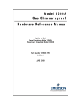
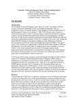
The EIA/TIA-422 communications uses a four wire (full duplex) system. There are
two separate lines for transmitting, and two lines for receiving data between the
computer and the Series 733/734. With EIA/TIA-422 you can have from one to ten
Series 733/734 controls connected to a single computer.
This diagram is a typical wiring example. The connections on the host computer
may vary depending on models. See page 7 for information about serial interfaces.
Refer to your computer user's manual for more information.
Figure 1 EIA/TIA-422 Interface, Wiring Diagram.
T+
TR+
RCom
Series
733 / 734
#1
˜
NOTE:
The Electronic
Industry Association (EIA) EIA/TIA422 standard
recommends a
maximum 4000 ft.
total network
distance.
4
WATLOW Series 733/734
T+
TR+
RCom
Series
733 / 734
#2
12
11
10
9
8
7
6
5
4
3
2
1
12
11
10
9
8
7
6
5
4
3
2
1
Twisted Pair Wire
Twisted Pair Wire
Common Pin 8
Twisted Pair Wire
Twisted Pair Wire
Common Pin 8
R+
RT+
TCom
B'
A'
B
A
Gnd.
EIA/TIA-232
to
EIA/TIA-422
Converter
How to Use Data Communications
RS-423
EIA/TIA-423 Interface Pinouts (EIA/TIA-232 Compatible)
73xx-xxxx-xBxx
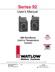
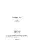
The EIA/TIA-423 communications uses a three wire (full duplex) system. There is
a separate line for transmitting, a line for receiving data, and a line for signal
common between the computer and the Series 733/734. With EIA/TIA-423 you
can have only one Series 733/734 control connected to a single computer.
This diagram is a typical wiring example. The connections on the host computer
may vary depending on models. Refer to your computer user's manual for more
information.
12
Transmit 11
10
Receive 9
Common 8
7
6
5
4
3
Series 733
(1 unit only) 2
1
DB-9 Pinouts
1 DCD
2 receive
3 transmit
4 DTR
5 common
6 DSR
7 RTS
8 CTS
1 2 3 4 5
6 7 8 9
DB-9 female viewed from wire side
(typical connections with jumpers)
How to Use Data Communications
Figure 2 EIA/TIA-423 Interface, Pin Designations.
˜
NOTE:
The Electronic
Industry Association (EIA) EIA/TIA423 standard
recommends a
maximum 50 foot
total point-to-point
distance.
WATLOW Series 733/734
5
EIA-485
EIA/TIA-485 Interface Pinouts
73xx-xxxx-xDxx
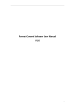
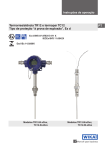
The EIA/TIA-485 communications uses a two wire (half duplex) system. There are
only two lines, both lines used for transmitting and receiving. Only one device, the
computer or the control, can be speaking at a time. The Series 733/734 requires a
7 millisecond delay between transmission and receipt of data. With EIA/TIA-485
you can have from one to thirty-two Series 733/734 controls connected to a computer.
This diagram is a typical wiring example. The connections on the host computer
may vary depending on models. See page 7 for information about serial interfaces.
Refer to your computer user's manual for more information.
Figure 3 EIA/TIA-485 Interface, Pin Designations.
T+ / R+
T- / R-
Com
12
11
Twisted Pair Wire
10
9
8
7
Common Pin 8
6
5
4
3
Series 733
#1
T+ / R+
T- / R-
˜
Com
NOTE:
The Electronic
Industry Association EIA/TIA-485
standard recommends a maximum
4000 ft. total network distance.
Series 733
#2
2
1
12
11
10
9
8
Twisted Pair Wire
Common Pin 8
T+ / R+
T- / R-
Com
7
6
5
4
3
2
B
A
Gnd.
EIA/TIA-485
Interface
1
Connecting the Control and the Computer
Remove power from both the Series 733/734 and your computer before connecting
them together. This prevents noise or static interference from entering the data
communication lines. Assemble a cable and the appropriate wiring at your computer. Refer to the wiring on pages 4 through 6. As soon as you connect the data
communications lines, you may apply power to your system.
6
WATLOW Series 733/734
How to Use Data Communications
Configuration
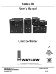
Figure 4 Internal EIA/TIA-422
& EIA/TIA-423 Switch
Location and Selection.
Series
733/734
(rear view)
˜
EIA/TIA-422 (C2) ← → EIA/TIA-423 (C1)
NOTE:
The Series 733/734
leaves the factory
configured for
EIA/TIA-423 operation, unless otherwise requested.
Communications Board
How to Set the EIA/TIA-422 & EIA/TIA-423 Hardware
Protocol Switches for 73xx-xxxx-xBxx Units Only
The EIA/TIA-422 or EIA/TIA-423 switches are on the Communication Module Board
(A007-1830) inside the control. Figure 4 shows the approximate location of this
board. Select C1 on both switches for EIA/TIA-423, or C2 on both switches for EIA/
TIA-422 operation. Both switches must be set to the same position.
To change the position of the switches:
Watlow recommends using a properly grounded wrist strap before opening
this control.
1) Remove power from the Series 733/734.
2. Remove the two snap-on connectors from the back of the unit.
2) Remove the two rear cover screws from the back of the unit.
3) Remove the rear cover and locate the switches. See Figure 4.
4) Set both switches to C1 for EIA/TIA-423, or to C2 for EIA/TIA-422
5) Replace the rear cover; secure the two rear cover screws.
6. Re-attach the two snap-on connectors.
7. Apply power to the control.
Your Computer's Serial Interface:
The Key To Network Connections
You can connect a data communication-equipped Series 733/734 to any computer
with an EIA/TIA-422 or EIA/TIA-423 (EIA/TIA-232 compatible) or EIA/TIA-485 serial
interface. The IBM™PC® with an EIA/TIA-232 serial output card, for instance, will
talk to a single EIA/TIA-423 equipped Series 733/734. For a multiple 733/734
network with the same PC, you'll need an EIA/TIA-232 to EIA/TIA-422 converter to
act as a "bus," or multiple connection point.
Watlow recommends the Burr-Brown LDM 422 for that purpose. The address is:
Burr-Brown, Inc., 1141 West Grant Rd,. Suite 131, Tucson, AZ 85705,
Phone: (602) 624-2434, Fax: (602) 623-8965.
For EIA/TIA-485, we recommend the Black Box LD485A-MP. The address is:
Black Box Corp., Mayview Road at Park Drive, Box 12800, Pittsburgh, PA 15241,
Phone: (412) 746-5530, Fax: (412) 746-0746.
How to Use Data Communications
WATLOW Series 733/734
7
Comms Setup
Program Mode - Communications Prompts
Enter the Program Mode at the front panel: [0)º0]
Press key sequence:
The display shows: [C_F`]
Continue pressing:
Until: [bAUd]
Current value displays alternately: [1200] or [bAUd]
Press to change value:
or
Press for next prompt:
Press to exit:
Document any changes.
Enter data on a photocopy of this page.
Table 1 Program Mode
prompts and Descriptions.
Prompt
[bAUd]
[dAtA]
8
This
Value
Range
Factory
Default
Appears…
(Baud rate)
300, 600, 1200, 2400, 4800, 9600
1200
if comms unit
7o = 7 data bits and odd parity
7E = 7 data bits and even parity
8n = 8 data bits and no parity
(Start bit = 1)
(Stop bit = 1)
7o
(Fixed)
(Fixed)
if comms unit
[Prot]
FULL = ANSI X3.28 2.2 - A.3
On = XON - XOFF
FULL
if comms unit
[Addr]
0 to 31 (ASCII)
0
if Prot = FULL
WATLOW Series 733/734
How to Use Data Communications
Read ASCII
ASCII Character Set
Dec
00
01
02
03
04
05
06
07
08
09
10
11
12
13
14
15
Hex
00
01
02
03
04
05
06
07
08
09
0A
0B
0C
0D
0E
0F
Char
NUL
SOH
STX
ETX
EOT
ENQ
ACK
BEL
BS
HT
LF
VT
FF
CR
SO
SI
Dec
16
17
18
19
20
21
22
23
24
25
26
27
28
29
30
31
Hex
10
11
12
13
14
15
16
17
18
19
1A
1B
1C
1D
1E
1F
Char
DLE
DC1
DC2
DC3
DC4
NAK
SYN
ETB
CAN
EM
SUB
ESC
FS
GS
RS
US
Dec
32
33
34
35
36
37
38
39
40
41
42
43
44
45
46
47
Hex
20
21
22
23
24
25
26
27
28
29
2A
2B
2C
2D
2E
2F
Char
SP
!
"
#
$
%
&
'
(
)
*
+
,
.
/
Dec
48
49
50
51
52
53
54
55
56
57
58
59
60
61
62
63
Hex
30
31
32
33
34
35
36
37
38
39
3A
3B
3C
3D
3E
3F
Char
0
1
2
3
4
5
6
7
8
9
:
;
<
=
>
?
Dec
64
65
66
67
68
69
70
71
72
73
74
75
76
77
78
79
Hex
40
41
42
43
44
45
46
47
48
49
4A
4B
4C
4D
4E
4F
Char
@
A
B
C
D
E
F
G
H
I
J
K
L
M
N
O
Dec
80
81
82
83
84
85
86
87
88
89
90
91
92
93
94
95
Hex
50
51
52
53
54
55
56
57
58
59
5A
5B
5C
5D
5E
5F
Char
P
Q
R
S
T
U
V
W
X
Y
Z
[
\
]
^
_
Dec
96
97
98
99
100
101
102
103
104
105
106
107
108
109
110
111
Hex
60
61
62
63
64
65
66
67
68
69
6A
6B
6C
6D
6E
6F
Char
`
a
b
c
d
e
f
g
h
i
j
k
l
m
n
o
Dec
112
113
114
115
116
117
118
119
120
121
122
123
124
125
126
127
Hex
70
71
72
73
74
75
76
77
78
79
7A
7B
7C
7D
7E
7F
Char
p
q
r
s
t
u
v
w
x
y
z
{
|
}
~
DEL
Table 2 ASCII Character
Set.
ASCII Control Characters (Partial Set)
ASCII
Char.
ENQ
ACK
NAK
STX
ETX
EOT
DLE
CR
DC1
DC3
Ctrl Key
Equiv.
Ctrl E
Ctrl F
Ctrl U
Ctrl B
Ctrl C
Ctrl D
Ctrl P
Ctrl M
Ctrl Q
Ctrl S
Definition
Enquiry
Acknowledge
Neg. Acknowledge
Start of Text
End of Text
End of Transmission
Data Link Escape
Carriage Return
XON
XOFF
How to Use Data Communications
Dec.
Equiv.
5
6
21
2
3
4
16
13
17
19
Hex.
Equiv.
05
06
15
02
03
04
10
0D
11
13
Table 3 ASCII Control
Characters
(Partial Set).
WATLOW Series 733/734
9
Learn Syntax
Series 733/734 General Message Syntax
As soon as you link the devices, you'll be able to talk to the Series 733/734 using
ASCII characters.
The Series 733/734 will respond to any Operation or Program prompt, plus some
others. The control will respond to either upper or lower case ASCII characters
from your computer.
Both protocol/interface combinations will respond to the general syntax, providing
the commands or queries are correctly transmitted. However, the ANSI X3.28
Protocol requires beginning and ending characters, and the XON/XOFF Protocol
requires ending characters. We'll look at those shortly.
Message Syntax
Messages from your computer to the Series 733/734 must take this general form.
All commands do not require the full number of data fields.
Command <space> data.1 <space> data.2 <space> data.3... data.N
"Command" is a character set to which the Series 733/734 will respond. The
brackets "< >" enclose a non-literal description. "Space" is simply a delimiter, an
ASCII space character (Hex 20). "Data Fields" are prompts and values specific to
a command; the number of possible data fields depends on the particular command you use. Data 1 is here abbreviated, "data.1", Data 2 is "data.2" and so on.
In the syntax explanations ahead, we'll show you the specific arguments for each
command. It will speed the process, if you remember this general syntax.
Data Rules
Data fields are prompts and values specific to particular commands. These rules
govern their use. Specific data for each command is listed later in this chapter.
• Data will be ASCII 0 through 9, unless otherwise noted.
• Data can go up to seven total characters, including a minus sign. A + or - sign, if
used, must be first, and it must have a decimal point if applicable.
• Data can use leading zeros. (Up to 7 digits.)
• Data does use decimal points.
• Data.1 portion of message can be up to four total characters.
Command List
These commands, represented by their respective ASCII characters, will enable
you to program the Series 733/734 from your computer. More detailed descriptions of the commands are in Table 5, pages 17-19.
?
=
10
WATLOW Series 733/734
Finds the value of a specific prompt.
Sets a specific prompt to a specific value.
p. 17 - 19
p. 17 - 19
How to Use Data Communications
See Syntax
Example Format
For your benefit, we're presenting message/response examples with syntax
required for Series 733/734 communication. Information bracketed by < > indicates a description, rather than literal characters. We show each ASCII character
that you must transmit to the Series 733/734, including space between the characters. (A "space" is itself an ASCII character, hex 20). For clarity, we also represent
each ASCII character as a hexadecimal pair. The pairs are spread apart on the
page for easy reading. However, electronic devices "see" the hex pairs all together
in "strings," with no spaces in between.
For instance, from the example just below, you want to set the Alarm 1 Low
(A1LO) prompt to 500°. Notice the syntax just below which uses the "=" command.
= <space> A1LO <space> 500
=
<Space>
A
ASCII
Characters
1
L O
Space
5
0
Figure 5 Series 733/734
General Message
Syntax Example.
0 <CR>
HEX
Value
3D 20 41 31 4C 4F 20 35 30 30 0D
To send this message, key the ASCII characters into your computer, or write them
into your program. The computer, in turn, will send a string similar to the one at the
bottom of the example, 3D2041314C4F20353030.
Notice that we haven't mentioned protocol here, or any characters added to this
syntax by a protocol. With XON/XOFF, the message above can be transmitted
with only an additional Carriage Return <cr> (hex 0D) character at the end. However, the ANSI X3.28 Protocol requires an envelope of Start of Text <STX> (hex
02) and End of Text <ETX> (hex 03) characters around the information you see
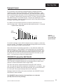
above. You'll learn how to do that in the pages ahead.
XON/XOFF Protocol for EIA/TIA-423
XON/XOFF (flow control) Protocol allows a communicating device (either a 733/
734 or the host) to suspend transmission of all messages from the other device,
and then to continue transmission when it's again ready.
The device that needs to suspend transmission sends the XOFF character
(hex 13) to stop the other device's transmitter, and XON (hex 11) to restart it. Note
that technically any character will restart the transmitter, but only the XON character is not a part of any regular message that may be transferring.
Messages transmit according to the syntax described in the XON/XOFF formats
which follow for each command.
The XON/XOFF Protocol requires a Carriage Return <cr> character
(hex 0D) at the end of every message.
How to Use Data Communications
WATLOW Series 733/734
11
XON/XOFF "="
How To Start and Stop Communicating
with the Series 733/734 and XON/XOFF
Starting communications with XON/XOFF Protocol is simple. You just configure
your computer to agree with the Series 733/734 communication prompts and open
its serial communication port in software. Then begin to "talk" by transmitting a
message to the Series 733/734. You stop communicating with XON/XOFF Protocol simply by ceasing to send messages.
XON/XOFF "=" Command Example
The general command syntax is the one you've already seen. Each command
uses a slightly different variation of it, depending on the number of arguments
required for a message.
• You want to change the Alarm 1 Low (A1LO) value to 500°. The "=" command
will do the job.
The syntax with XON/XOFF Protocol requires an ending Carriage Return
<cr>.
"=" Command Syntax with XON/XOFF Protocol:
= <space> data.1 <space> data.2 <cr>
With the "=" Command, data.1 is the Series 733/734 prompt, in this case Alarm 1
Low, A1LO. Data.2 is the value you want to set for that prompt, in this example,
500.
Enter in ASCII:
= <space> A1LO <space> 500 <cr>
The hex string will be:
3D2041314C4F203530300D
=
<Space>
A
ASCII
Characters
Figure 6 XON/XOFF "="
Command Example.
1
L O
Space
5
0
0 <CR>
HEX
Value
3D 20 41 31 4C 4F 20 35 30 30 0D
Response from the Series 733/734:
It sends an "XOFF" when a carriage return is received and then an "XON" when
the unit is done processing the command.
• The complete list of Commands is in Table 5, Pages 17-19.
<XOFF> <XON>
13
12
WATLOW Series 733/734
11
How to Use Data Communications
XON/XOFF "?"
XON/XOFF "?" Command Example
You want to know the Alarm 1 Low (A1LO) value. The "?" uses a variation of the
message syntax shown just below. This protocol requires an ending carriage
return character.
"?" Command syntax with XON/XOFF Protocol:
? <space> data.1 <cr>
Enter in ASCII:
? <space> A1LO <cr>
The hex string will be:
3F2041314C4F0D
?
Space
A
1
ASCII
Characters
HEX
Value
L
Figure 7 XON/XOFF "?"
Command Example.
O ace
CR
3F 2 0 4 1 3 1 4C 4F 0 0D
The value of A1LO will be between rL (Range Low) and rH (Range High), say, 500.
Response from the Series 733/734:
<XOFF> <XON> <current value of A1LO> <cr>
The hex response string is:
13113530300D
<XOFF>
<XON>
5
ASCII
Characters
0
0
CR
HEX
Value
13
11
How to Use Data Communications
35 30
30 0D
WATLOW Series 733/734
13
ANSI X3.28
ANSI X3.28 Protocol for EIA/TIA-422 and EIA/TIA-485
The ANSI X3.28 Protocol provides high quality communications by requiring a
response to every message. With a multiple device or "multidrop" network, this
protocol prevents confusion among the separate devices. Furthermore, if noise
occurs somewhere in the system, no prompt will change because noise can't
comply with the protocol.
By placing messages inside a protocol envelope, the messages are protected. In
the examples to come you'll see how this works.
The ANSI X3.28 Protocol requires STX characters at the beginning of a
message and ETX characters at the end.
Device Address
If you are using the ANSI X3.28 Protocol, you must have a device address (identification) number. A Watlow EIA/TIA-422 multidrop network can handle up to 10
devices with this protocol. EIA/TIA-485 can handle up to 32 devices.
Set the address number with the Series 733/734 in the Addr prompt under the
Setup menu.
Address
0-9
10 - 31
Table 4 Address to ASCII
Conversion.
ASCII Equivalent
0-9
A-V
Starting Communications in ANSI X3.28 Protocol
Here's the syntax for starting communications with ANSI X3.28 Protocol. The
master device, your computer, must initiate the data link. The example below
uses the ASCII number 4 as a Series 733/734 device address.
Enter in ASCII, using this syntax: <Address # 4><ENQ>
ASCII
Characters
HEX Value
4
<ENQ>
34 05
Response from the 733/734:
<Address # 4><Acknowledge (ACK)>
ASCII
Characters
HEX Value
14
WATLOW Series 733/734
4
<ACK>
34 06
How to Use Data Communications
ANSI X3.28 "="
Stopping Communications in ANSI X3.28 Protocol
The master device, your computer, must end communications with Device #4 by
using Data Link Escape (DLE) and End of Transmission (EOT) characters.
Enter in ASCII: <DLE> <EOT>
ASCII
Characters
HEX Value
<DLE>
<EOT>
10 04
Response from the 733/734:
None
ANSI X3.28 "=" Command Example
The "=" Command sets a specific 733/734 prompt to a specific value. The general
command syntax applies to all commands. The definition and number of arguments depends on the command itself. See Table 5, Pages 17.
In this example, you want to change the Alarm 1 Low value to 500°. Here, the "="
command will do the job.
'"=" command Syntax with ANSI X3.28 Protocol:
<STX> = <space> data.1 <space> data.2 <ETX>
With the "=" command, data.1 is the Series 733/734 prompt, in this case Alarm 1
Low , A1LO. Data.2 is the value you want to set for that prompt, in this example,
500.
Enter in ASCII:
<STX> = <space> A1LO <space> 500 <optional carriage return> <ETX>
The hex string is:
023D2041314C4F2035303003
<STX>
=
<Space>
A
ASCII
Character
1
L
O Space
5
0
HEX
Value
0 <ETX>
Figure 8 ANSI X3.28 "="
Command Example.
02 3D 20 41 31 4C 4F 20 35 30 30 03
Optional
Carriage
Return
How to Use Data Communications
WATLOW Series 733/734
15
ANSI X3.28 "?"
Response from the Series 733/734:
<ACK>
The hex response string is:
06
• You'll find the the complete list of "=" command arguments (prompts and value
limits) in Table 5, Pages 17-19.
ANSI X3.28 "?" Command Example
You need to know the Alarm 1 Low value (A1LO). The "?" uses a variation of the
message syntax shown just below. This syntax requires the protocol start of
text and end of text characters.
"?" command syntax with ANSI X3.28 Protocol:
<STX> ?<space> <data.1> <ETX>
Enter in ASCII:
<STX> ? <space> <A1LO> <optional carriage return> <ETX>
The hex string will be:
023F2041314C4F03
Optional
<STX>
?
Space
A
Figure 9 ANSI X3.28 "?"
Command Example.
ASCII
Characters
HEX
Value
Carriage
Return
1
L O
<ETX>
02 3F 20 41 31 4C 4F 03
First response from the Series 733/734:
<ACK>
The <ACK> hex response string is:
06
Your computer's confirming response:
<EOT>
The <EOT> response hex string is:
04
Second response from the Series 733/734:
<STX> <current A1LO value> <carriage return> <ETX>
The hex string is:
023530302003
<STX>
ASCII
5
Characters
0
0
<cr><ETX>
HEX
Value
02
35
30
30
20
03
Your computer's next response:
<ACK> or < NAK> (if the message needs to be repeated).
The hex string is:
06 or 15
Final response from the Series 733/734:
<EOT>
The hex string is:
04
16
WATLOW Series 733/734
How to Use Data Communications
Commands
Command Summary Series 733/734 Data Communications
Name Description
Read (?) and/or Write (=) Syntax
Range
(data.1)
Add ETX & STX with ANSI X3.28 Protocol
(data.2)
? <sp> A1HI <cr>
= <sp> A1HI <sp> data.2 <cr>
Process Alarm: A1LO to R1H
Deviation Alarm:
0 to 555°C/0 to 999°F
A1LO Zone 1 Alarm Low
? <sp> A1LO <cr>
= <sp> A1LO <sp> data.2 <cr>
Process Alarm: R1L to A1HI
Deviation Alarm:
0 to -555°C/0 to -999°F
A2HI
? <sp> A2HI <cr>
= <sp> A2HI <sp> data.2 <cr>
Process Alarm: A2LO to R2H
Deviation Alarm:
0 to 555°C/0 to 999°F or Units
A2LO Zone 2 Alarm Low
? <sp> A2LO <cr>
= <sp> A2LO <sp> data.2 <cr>
Process Alarm: R2L to A2HI
Deviation Alarm:
0 to -555°C/0 to -999°F or Units
AL1
Zone 1 Alarm Type
? <sp> AL1 <cr>
= <sp> AL1 <sp> data.2 <cr>
0 = Process Alarm
1 = Deviation Alarm
2 = No Alarm
AL2
Zone 2 Alarm Type
? <sp> AL2 <cr>
= <sp> AL2 <sp> data.2 <cr>
0 = Process Alarm
1 = Deviation Alarm
2 = No Alarm
ALM
Alarm Status
(Writing a 0 will clear
all alarms if all alarm
conditions no longer
exist.)
? <sp> ALM <cr>
= <sp> ALM <sp> 0 <cr>
0 = No alarms occurring
1 = A1HI occurring
2 = A1LO occurring
4 = A2HI occurring
8 = A2LO occurring
AUT1
Zone 1 Auto-tune
? <sp> AUT1 <cr>
= <sp> AUT1 <sp> data.2 <cr>
0 = No auto-tuning
1 = Slow response tuning
2 = Medium response tuning
3 = Fast response tuning
AUT2
Zone 2 Auto-tune
? <sp> AUT2 <cr>
= <sp> AUT2 <sp> data.2 <cr>
0 = No auto-tuning
1 = Slow response tuning
2 = Medium response tuning
3 = Fast response tuning
C1
Zone 1 Process Value ? <sp> C1 <cr>
Between R1L and R1H
C2
Zone 2 Process Value ? <sp> C2 <cr>
Between R2L and R2H
CAL1
Zone 1 Cal Offset
? <sp> CAL1 <cr>
= <sp> CAL1 <sp> data.2 <cr>
-99°F to 99°F
-55°C to 55°C
CAL2
Zone 2 Cal Offset
? <sp> CAL2 <cr>
= <sp> CAL2 <sp> data.2 <cr>
-99°F to 99°F
-55°C to 55°C
-99 Units to 99 Units
CF
Degrees Select
? <sp> CF <cr>
= <sp> CF <sp> data.2 <cr>
0 = Display °F
1 = Display °C
CSP
Current Set Point
? <sp> CSP <sp> zone <cr>
0 = Zone 1
1 = Zone 2
CT1
Zone 1 Cycle Time
? <sp> CT1 <cr>
= <sp> CT1 <sp> data.2 <cr>
1 to 60 seconds
CT2
Zone 2 Cycle Time
? <sp> CT2 <cr>
= <sp> CT2 <sp> data.2 <cr>
1 to 60 seconds
A1HI
Zone 1 Alarm High
Zone 2 Alarm High
Table 5 Command Summary
with Read (?) and
Write (=) Simple
Syntax and Data
Range/Responses.
Table continued on the next page.
How to Use Data Communications
WATLOW Series 733/734
17
Commands
Name Description
Read (?) and/or Write (=) Syntax
Range
(data.1)
Add ETX & STX with ANSI X3.28 Protocol
(data.2)
ER1
Error 1 Code
(Multiple errors
possible.)
? <sp> ER1 <cr>
= <sp> ER1 <sp> 0 <cr>
0 = No error
1 = ROM error
2 = RAM error
3 = Ambient sensor error
4 = Configuration error
5 = EEprom error
6 = A/D underflow error, Zone 1
7 = A/D overflow error, Zone 1
8 = A/D underflow error, Zone 2
9 = A/D overflow error, Zone 2
10 = Stack overflow error
11 = Open sensor, Zone 1
12 = Shorted sensor, Zone 1
13 = Open sensor, Zone 2
14 = Shorted sensor, Zone 2
15 = Loop error, Zone 1
16 = Loop error, Zone 2
ER2
Error 2 Code
? <sp> ER2 <cr>
0 = No error
1 = Transmit buffer overflow
2 = Receive buffer overflow
3 = Framing error
4 = Overrun error
5 = Parity error
6 = Talking out of turn
7 = Invalid reply error
8 = Noise error
20 = Command not found
21 = Prompt not found
22 = Incomplete command line
23 = Invalid character
24 = Number of chars. overflow
25 = Input out of limit
26 = Read only command
27 = Write allowed only
GB
Guard Band
? <sp> GB <cr>
= <sp> GB <sp> data.2 <cr>
1 to 4000°F
1 to 2222°C
1 to 4000 Units
HYS1
Zone 1 Hysteresis
? <sp> HYS1 <cr>
= <sp> HYS1 <sp> data.2 <cr>
1 to 99°F
1 to 55°C
HYS2
Zone 2 Hysteresis
? <sp> HYS2 <cr>
= <sp> HYS2 <sp> data.2 <cr>
1 to 99°F
1 to 55°C
1 to 99 Units
INP1
Zone 1 Input Type
? <sp> INP1 <cr>
= <sp> INP1 <sp> data.2 <cr>
0 = J t/c; 32 to 1382°F/0 to 750°C
1 = K t/c; 32 to 2282°F/0 to 1250°C
2 = E t/c; 32 to 1220°F/0 to 660°C
3 = RTD; 32 to 1112°F/0 to 600°C
INP2
Zone 2 Input Type
? <sp> INP2 <cr>
= <sp> INP2 <sp> data.2 <cr>
0 = J t/c; 32 to 1382°F/0 to 750°C
1 = K t/c; 32 to 2282°F/0 to 1250°C
2 = E t/c; 32 to 1220°F/0 to 660°C
3 = RTD; 32 to 1112°F/0 to 600°C
4 = 0-5V; -500 to 3500 units
5 = 4-20mA; -500 to 3500 units
6 = 0-10V; -500 to 3500 units
7 = 0-20mA; -500 to 3500 units
LAT
Alarm Latching
? <sp> LAT <cr>
= <sp> LAT <sp> data.2 <cr>
0 = Non-latched alarms
1 = Latched alarms
LOC
Keyboard Lock
? <sp> LOC <cr>
= <sp> LOC <sp> data.2 <cr>
0 = Enable prompt change
1 = Disable prompt change
LOOP Loop Failure
? <sp> LOOP <cr>
= <sp> LOOP <sp> data.2 <cr>
0 = Loop fail check OFF
1 = Loop fail check ON
LI
? <sp> LI <cr>
Response depends on 733 hardware and LI switch positions.
Change a switch and retry; a
switch change = logic data chg.
Table 5 Command Summary
with Read (?) and
Write (=) Simple
Syntax and Data
Range/Responses.
Logic Input Test
Table continued on the next page.
18
WATLOW Series 733/734
How to Use Data Communications
Name Description
Read (?) and/or Write (=) Syntax
Range
(data.1)
Add ETX & STX with ANSI X3.28 Protocol
(data.2)
MDKY Mode Key Action
= <sp> MDKY <sp> 1 <cr>
1 = One MODE Key press
MDL
? <sp> MDL <cr>
x1 = 3 or 4; horiz. or vert. unit
x2 & x3 = Last two
characters of model #, AA-XX
x4 = Software rev; 0-9 or A-X
Model Number
Responds 73x-xx-x
(See Model # , p. 21)
MENU Menu Step
? <sp> MENU <sp> menu
<sp> step <cr>
= <sp> MENU <sp> menu <sp>
step <sp> sp1 <sp> sp2 <sp>
hours or minutes <sp> minutes or
seconds <sp> events <cr>
Data entered must be within
individual prompt guidelines,
i.e., SP1 = R1L to R1H, etc.
Enter data for sp2 and events
even if they are not available.
See 733/4 Program Manual.
MODE Mode Status
? <sp> MODE <cr>
0 = Operation mode
1 = Program mode
2 = Setup mode
3 = Service mode
4 = Calibration mode
MS
Melt Cycle
? <sp> MS <cr>
= <sp> MS <sp> data.2 <cr>
0 = Melt cycle OFF
1 = Melt cycle ON
PB1
Zone 1 Prop Band
? <sp> PB1 <cr>
= <sp> PB1 <sp> data.2 <cr>
0 to 999°F
0 to 555°C
PB2
Zone 2 Prop Band
? <sp> PB2 <cr>
= <sp> PB2 <sp> data.2 <cr>
0 to 999°F
0 to 555°C
0 to 999 Units
RA1
Zone 1 Rate
? <sp> RA1 <cr>
= <sp> RA1 <sp> data.2 <cr>
0 to 9.99 minutes
RA2
Zone 2 Rate
? <sp> RA2 <cr>
= <sp> RA2 <sp> data.2 <cr>
0 to 9.99 minutes
RE1
Zone 1 Reset
? <sp> RE1 <cr>
= <sp> RE1 <sp> data.2 <cr>
0 to 9.99 repeats per minute
RE2
Zone 2 Reset
? <sp> RE2 <cr>
= <sp> RE2 <sp> data.2 <cr>
0 to 9.99 repeats per minute
RH1
Zone 1 Range High
? <sp> RH1 <cr>
= <sp> RH1 <sp> data.2 <cr>
RL1 to max. INP1 type range
RH2
Zone 2 Range High
? <sp> RH2 <cr>
= <sp> RH2 <sp> data.2 <cr>
RL2 to max. INP2 type range
RL1
Zone 1 Range Low
? <sp> RL1 <cr>
= <sp> RL1 <sp> data.2 <cr>
Min. INP1 type range to RH1
RL2
Zone 2 Range Low
? <sp> RL2 <cr>
= <sp> RL2 <sp> data.2 <cr>
Min. INP2 type range to RH2
RTD
RTD Curve
? <sp> RTD <cr>
= <sp> RTD <sp> data.2 <cr>
0 = DIN
1 = JIS
RUN
Menu Run
= <sp> RUN <sp> menu <cr>
n = Run Menu n
SIL
Alarm Silence
? <sp> SIL <cr>
= <sp> SIL <sp> data.2 <cr>
0 = OFF
1 = ON
STAT
Run Status
? <sp> STAT <cr>
x x; x1=0 idle or 1 run, x2=menu#
STP
Maximum Steps
? <sp> STP <cr>
= <sp> STP <sp> data.2 <cr>
1 = 1 Step
2 = 2 Steps
3 = 3 Steps
STOP Menu Stop
= <sp> STOP menu <cr>
n = Stop Menu n
TCMP Temperature
Compensation
? <sp> TCMP <cr>
= <sp> TCMP <sp> data.2 <cr>
0 = OFF
1 = ON
TREM Time Remaining
? <sp> TREM <cr>
Learn Menu time remaining
TS
? <sp> TS <cr>
= <sp> TS <sp> data.2 <cr>
0 = minutes : seconds
1 = hours : minutes
Time Select
How to Use Data Communications
Commands
Table 5 Command Summary
with Read (?) and
Write (=) Simple
Syntax and Data
Range/Responses.
WATLOW Series 733/734
19
Errors
NAKs and Error Codes
When your message is "not acknowledged" (NAK) in EIA/TIA-422 or EIA/TIA-485
with ANSI X3.28 Protocol, you may clear ER2 codes by reading it. That is, use "?"
Then try the message again; you may have made a syntax error. See the error
code listing in Table 5, page 17.
With XON/XOFF protocol and the EIA/TIA-423 interface, the 733/734 sends no
feedback on commands. Therefore, you may want to query the status of ER2 after
each command you send.
All communications-related error codes are ER2 error codes, that is they are not
considered cause for a shutdown of the 733/734 unit itself. There is always a
communications error code generated when a <NAK> character is sent under the
ANSI X3.28. With XON/XOFF flow control error codes may be generated, but
there will be no standard indication of this fact.
ç
User Responsibility
CAUTION:
Sending commands
to a particular
Series 733/734 for
which it is not
equipped may cause
damage to equipment and/or
processes.
20
ç
All data communications commands are available on all models of the Series 733/
734 which have communications capability. Users must refrain from altering
prompts which do not appear on the Series 733/734 front panel. For example, do
not send an A1LO command, page 17, to a Series 733/734 not equipped with
alarm outputs.
The exception to this rule concerns the MENU command, which requires valid data
for SP2 (Set Point 2) and events, even though the hardware is not present in the
particular Series 733/734.
WATLOW Series 733/734
How to Use Data Communications
Model Number
7 3 _A-____-__AA
733/734 = One or two channel microprocessor-based, time and
temperature control; 24VÅ (VAC) power input.
*Order power supply and connector kit(s) separately below.
Display Orientation
3 = Horizontal
4 = Vertical
Display Location
A = Integral (local)
Input Type
1 = Single thermocouple (type J, K E)
2 = Single RTD 1°, curve selectable
4 = Dual thermocouple (type J, K, E); Order output types 1 & 2
5 = Dual RTD 1°, curve selectable; Order output types 1 & 2
6 = Dual Input: Channel 1 thermocouple (type J, K, E); and Channel 2
process (0-5VÎ (VDC), 0-10VÎ (VDC), 0-20mA, 4-20mA), Order output types 1 & 2
Dual-zone units must use ungrounded thermocouples.
Output 1 Type
B = Solid-state relay with RC suppression, form A, 0.4A
C = Switched DC, open collector, non-isolated
D = Mechanical relay, form A, 1A, with suppression
E = Mechanical relay, form A, 1A, without suppression
F = Process, 4-20mA, non-isolated
H = Process, 0-5VÎ (VDC), non-isolated
K = Solid-state relay without RC suppression, form A, 0.4A
Output 2 Type
A = None
B = Solid-state relay with RC suppression, form A, 0.4A
C = Switched DC, open collector, non-isolated
D = Mechanical relay, form A, 1A, with suppression
E = Mechanical relay, form A, 1A, without suppression
F = Process, 4-20mA, non-isolated
H = Process, 0-5VÎ (VDC), non-isolated
K = Solid-state relay without RC suppression, form A, 0.4A
Event Inputs/Outputs
0 = None
1 = 4 Event outputs, switched DC, non-isolated (custom only)
Alarm
A =
D =
None
Single mechanical relay, form A, 1A, with suppression
Communications (Isolated)
A = None
B = EIA/TIA-422 or EIA/TIA-423
D = EIA/TIA-485
Options
AA = Standard Single Display
Power Supply, Power Connector and Event Input/Output Accessory Kits (Order separately here.)
Part No.
Description
A001-0249-0001 =
120VÅ (VAC) - 24VÅ (VAC), stepdown transformer, Class 2, quick connect terminals included.
A001-0249-0002 =
208/240VÅ (VAC) - 24VÅ (VAC), stepdown transformer, Class 2, quick connect terminals included.
A001-0250-0012 =
Power input connector kit, 12-pin connector assembly, wire not included.
A001-0250-0009 =
Event input/output connector kit, 9-pin connector assembly, wire not included.
How to Use Data Communications
WATLOW Series 733/734
21
22
WATLOW Series 733/734
How to Use Data Communications
A
Addr, 8
Address, 14
ALM, 17
ANSI X3.28 "=" Command, Fig. 8, 15
ANSI X3.28 "?" Command, Fig. 9, 16
ANSI X3.28 Protocol for EIA/TIA-422 & EIA/TIA485, 14
ASCII Character Set, Table 2, 9
ASCII Control Characters (Partial Set), Table 3, 9
A1HI, A2HI, 17
A1LO, A2LO, 17
AL1, AL2, 17
AUT1, AUT2, 17
B
bAUd, 8
Baud Rate, 8
C
C1, C2, 17
CAL1, CAL2, 17
Carriage Return, 11
CF, 8, 17
Command, "?" Example
ANSI X3.28, 16
XON/XOFF, 13
Command, "=" Example
ANSI X3.28, 15
XON/XOFF, 12
Command List, Table 5, 17-19
Communications
Prompts, 8
Switch Selection, 7
Wiring, 3
Connecting the Control and the Computer, 4-6, 7
CSP, 17
CT1, CT2, 17
D
dAtA, 8
Data Link Escape (DLE), 15
Data Rules, 10
Device Address, 8, 14
E
EIA/TIA-422, 3, 4
EIA/TIA-423, 3, 5
EIA/TIA-485, 3, 6
End of Text (ETX), 14
End of Transmission (EOT), 15
ER1, ER2, 18
Error Codes, 18, 20
Example Format, 11
F
Flow Control, 11
G
GB, 18
General Message Syntax, 10
H
Hardware Interface, 3, 7
HYS1, HYS2, 18
I
Identification Number, 14
INP1, INP2, 18
How to Use Data Communications
Interface Wiring,
EIA/TIA-422, Fig. 1, 4
EIA/TIA-423, Fig. 2, 5
EIA/TIA-485, Fig. 3, 6
Index
L
LAT, 18
LOC, 18
LOOP, 18
M
MDL, 19
MDKY, 18
MENU, 19
Message Syntax, 10
MODE, 19
MS, 19
Multidrop, 3
N
NAKs and Error Codes, 20
Network Connections, 7
P
PB1, PB2, 19
Prot, 8
Protocol
ANSI X3.28, 3, 7
XON-XOFF, 3, 7
Switches, 7
R
RA1, RA2, 19
RE1, RE2, 19
RH1, RH2, 19
RL1, RL2, 19
RTD, 19
RUN, 19
S
Serial Interface, 7
Setup Menu, 8
SIL, 19
Software Protocols, 3, 8
Space, 11
Starting Communications in ANSI X3.28 Protocol, 14
Start of Text (STX), 14
STAT, 19
STOP, 19
STP, 19
Stopping Communications in ANSI X3.28 Protocol, 15
Switches, Hardware Protocol, 7
T
TCMP, 19
TREM, 19
TS, 19
Two Hardware Interfaces & Protocols, 3
W
Wiring for Data Communications, 4-6
X
XON/XOFF
"=" Command Example, Fig. 6, 12
"?" Command Example, Fig. 7, 13
Protocol, 3, 7
Protocol for EIA/TIA-423, 13
Switches, 7
WATLOW Series 733/734
23
Series 733/734 Data Communications User's Manual
Watlow Controls, 1241 Bundy Blvd., P.O. Box 5580, Winona, MN 55987-5580, Phone: 507/454-5300, Fax: 507/452-4507
24
WATLOW Series 733/734
How to Use Data Communications