1
Program Version 5.11
INSTALLER
MANUAL
GDAŃSK
ca10i_en 05/09
WARNINGS
Due to safety reasons, alarm system should be installed by qualified personnel only.
Telephone terminals of the panel should be connected to PSTN lines only. Connecting to
ISDN lines may lead to damage of the equipment.
Because alarm system may contain hazardous items, its components should be kept out of
reach of unqualified personnel.
In order to avoid the risk of electric shock, read carefully this manual before proceeding to
installation. Any connections should be made in deenergized state only (i.e. with power
supply disconnected).
In the event of service operations consisting in fuse replacement, they must only be carried
out after disconnecting the supply voltage. For the replacement, use only the fuses which
have identical parameters as the original ones.
It is recommended that the manufacturer’s required housings and power supply units be
used.
Making any construction changes or unauthorized repairs is prohibited. This applies, in
particular, to modification of assemblies and components.
CAUTION !
It is impermissible to connect a fully discharged battery (voltage on terminals without a load
less than 11V) to the alarm panel. To avoid hardware damage, fully discharged or never used
battery should be precharged using proper charger.
The batteries used in the alarm systems contain lead. The old batteries must not be thrown
away, but disposed of as required by the existing regulations (European Directives
91/157/EEC and 83/86/EEC).
DECLARATION OF CONFORMITY
Manufacturer: SATEL spółka z o.o.
ul. Schuberta 79
80-172 Gdańsk, POLAND
tel. (+48 58) 320-94-00
fax. (+48 58) 320-94-01
Product description: Mainboard for CA-10 control panel intended for use in intruder alarm systems.
This product meets the essential requirements and is in conformity with following EU Directives:
LVD 2006/95/WE
EMC 89/336/EWG + 91/263/EEC, 92/31EEC, 93/68/EEC
R&TTE 1999/5/EC (network connection, TBR21)
This product is compliant with the following harmonized standards:
LVD: EN 50131-1:1997; EN 50131-6:1997; EN60950:2000, EN60335-1:1994/A1:1996 Annex B
EMC: EN 55022:1998 (Class A); EN 61000-3-2/-3; EN 50130-4:1995, EN 61000-4-2/-3/-4/-5/-6/-11
R&TTE: TBR 21(1998)
Head of Test Laboratory:
Gdańsk, Poland
02.07.2007
Michał Konarski
Latest EC declaration of conformity and product approval certificates can be downloaded from web site
www.satel.pl
Product:
CA10P – control panel CA-10
mainboard
WARNING!
This is a class A product. In a domestic environment this product may cause radio
interference in which case the user may be required to take adequate measures.
CONTENTS
GENERAL DESCRIPTION OF THE CONTROL PANEL ......................................................... 2
TECHNICAL DESCRIPTION OF THE CONTROL PANEL ...................................................... 2
Zones ................................................................................................................................... 2
Outputs................................................................................................................................. 4
Partitions .............................................................................................................................. 7
Access codes and authority levels ....................................................................................... 8
Keypads ............................................................................................................................... 9
LED Keypad ....................................................................................................................................................9
LCD Keypad ....................................................................................................................................................9
Monitoring .......................................................................................................................... 10
Dialer .................................................................................................................................. 11
Remote programming – DOWNLOADING ......................................................................... 11
INSTALLATION OF THE CONTROL PANEL ........................................................................ 13
Description of control panel main board ............................................................................. 13
Connection of keypads ....................................................................................................... 15
Setting keypad addresses .................................................................................................. 19
Connection of zone expander ............................................................................................ 19
Connection of detectors ..................................................................................................... 20
Connection of Sirens .......................................................................................................... 22
Connections of telephone line ............................................................................................ 24
Connection of voice synthesizer ......................................................................................... 24
Connection of printer or computer ...................................................................................... 25
Connection of power supply ............................................................................................... 26
Starting the control panel ................................................................................................... 26
Hardware access to the service mode ............................................................................... 27
Programming the control panel from the computer ............................................................ 28
ACTIVATING SELECTED FUNCTIONS................................................................................ 28
Guard control function ........................................................................................................ 28
Telephone messaging – alarm reporting ............................................................................ 28
Reporting to telephone monitoring station .......................................................................... 29
Downloading – telephone communication with the computer............................................. 31
Modem initialization ......................................................................................................................................31
Programming the LCD keypad from the computer ............................................................. 32
REMOTE PROGRAMMING – DLOAD10 .............................................................................. 33
Program configuration for communication with the panel .............................................................................34
DEFAULT SETTINGS............................................................................................................ 35
Control panel configuration (restore with FS 107 function): .........................................................................35
Communication identifiers (restore identifiers with FS109 function):............................................................36
Control panel access codes (restore codes with FS110 function):...............................................................36
TECHNICAL DATA ................................................................................................................ 37
GENERAL DESCRIPTION OF THE CONTROL PANEL
The CA-10 alarm control panel is advanced, microprocessor-based alarm control panel,
developed in accordance with the latest trends in the field of burglary and assault signaling.
Its comprehensive features and affordable price permit application of the CA-10 both in small
and medium-size alarm systems.
The alarm control panel incorporates a number of solutions, which were previously
encountered only in special purpose equipment.
Basic functional features:
• operating the panel from remote LCD text display keypads or from LED keypads,
• remote control by means of a telephone set (selected functions) – support of the MST-1
module,
• connection of up to four independent keypads,
• possibility of four-partition operation, with completely separate alarm systems, or
common zone partitions or internal partitions,
• 10 to 16 fully programmable zone inputs (8 zones on the main board, 2 on each
keypad, extension through zones of next keypads or expander), each capable of
performing one of 21 functions,
• support of any detectors in NO, NC, EOL and 2EOL configuration with individual zone
violation,
• 6 programmable outputs, each being able to perform any of 41 functions,
• built-in telephone communicator for:
- messaging to two monitoring stations,
- messaging alarm condition via pager systems,
- messaging alarm condition with voice announcement,
- answering a call and reporting the system status,
- remote service from a modem equipped computer,
• built-in RS-232 port with RJ socket makes it possible to connect a printer (for printing
event log or current data) and program the control panel from a PC,
• internal clock for automatically arming/disarming partitions with TIMER function,
• operating the system with independent access codes by 32 users (up to 13 in each
partition) – the codes can have different authority levels, and their use is recorded in the
event log,
• nonvolatile memory of 255 last events, which gathers information about arming,
disarming, alarms, troubles, etc., with date and time of occurrence, and panel user
number,
• possibility to supervise guard rounds with TIMER function,
• automatic monitoring of the alarm system performance, inclusive of finding a damaged or
blocked detector.
TECHNICAL DESCRIPTION OF THE CONTROL PANEL
Zones
In its basic configuration, the CA-10 control panel has 10 zones: 8 on the panel main board
and 2 in the keypad. In its full configuration, with four keypads (or an expander), the panel
has 16 zones available. The zones can support any detectors in the configuration NC, NO,
CA-10
Installer Manual
3
EOL, 2EOL/NC, 2EOL/NO. The use of 2EOL configuration enables the panel to
simultaneously control the detector and its tamper circuit by means of one pair of wires.
The zones can perform the following functions in the system:
0 – entry/exit – the violation of which, when in the armed mode, will start countdown of the entry delay
time and will enable the delay mechanism for INTERIOR DELAY type zones (violation of an
INTERIOR DELAY zone without prior violation of the ENTRY/EXIT zone will trigger an alarm
immediately). Upon violation, a “zone violation” code is sent to the report station (it is possible to skip
sending this message), and, after counting down the "entry delay time" and triggering the alarm
- a “zone alarm” code. The "entry delay" countdown can be signaled in the keypad. It is possible to
define automatically bypassing zones if no ENTRY/EXIT zone is violated during the exit delay time”.
Because of its additional functions, this zone type cannot be used as a common zone for several
partitions.
1 – delay – when violated in the armed mode, it starts delay countdown, after which an alarm is triggered.
It will not occur if the zone is disarmed before completion of the delay countdown. Upon violation,
a “zone violation” code is sent to the report station (it is possible to skip sending this message), and,
after counting down the "entry delay time" and triggering the alarm – a “zone alarm” code. The delay is
not signaled in the keypads.
2 – interior delay – when violated in the armed mode after previous violation of the ENTRY/EXIT zone, it
behaves like a DELAY zone. When violated in the armed mode without previous violation of the
ENTRY/EXIT zone, it behaves like an INSTANT zone.
3 – instant – when violated in the armed mode, it immediately triggers an alarm and sends a ”zone alarm”
message to the monitoring station.
4 – day/night – when violated in the armed mode, it behaves like an INSTANT zone, while when
disarmed, it will signal violation in the keypad (unless the signaling is disabled) and send a “zone
violation” code to the station.
5 – counting L1 – when violated in the armed mode, it increases the status of the first of three violation
counters (a „zone violation” code is sent to the station), until the number of violations specified for that
counter is exceeded (programming in FS7). Then, the violation triggers an alarm (a „zone alarm” code
is sent to the report station). The violation counter is reset after 30 seconds since the first violation.
It is possible to program another counter count-up time (FS123). If the preset number of violations is
not reached within this time, there will be no alarm. More than one zone can be define as “counting L1”.
Violations of those zones will be summed up. Violation of the counting zone in armed mode can be
signaled in the keypad in the same way as for the DAY/NIGHT zone.
6 – counting L2 – operation identical as for the "counting L1", but changes the status of the second of the
three counters.
7 – counting L3 – operation identical as for the "counting L1", but changes the status of the third of the
three counters.
8 – 24H audible – armed all the time, irrespective of whether the partition it is assigned to is armed, or not.
Each violation of this zone will trigger alarm on the BURGLARY ALARM type outputs, in the keypad, and
will send a “zone alarm” code. It makes possible to create tamper circuits and panic buttons.
9 – 24H auxiliary – armed all the time, irrespective of whether the partition it is assigned to is armed, or
not. Each violation of this zone will trigger an alarm in the keypad and will send a “zone alarm” code. It is
intended for connecting detectors not related to the burglary alarm, such as gas or flooding sensors, etc.
10 – 24H silent – armed all the time, irrespective of whether the partition it is assigned to is armed, or not.
Violation of this zone will only send a “zone alarm” code to the monitoring station.
11 – 24H fire – armed all the time, irrespective of whether the partition it is assigned to is armed, or not;
intended to manage the fire detectors.
If the control panel contains an output programmed as the FIRE DETECTORS POWER SUPPLY,
violation of the zone will actuate the alarm verification mechanism and will signal alarm in the keypad.
To perform the verification, disconnect momentarily power supply to the fire detectors and check,
whether after reconnection of power supply the violation will be repeated within 90 seconds. If that’s
the case, the control panel will send a „zone alarm” message to the monitoring station, activate the
FIRE ALARM and FIRE/BURGLARY ALARM outputs, and trigger the fire alarm (intermittent signal) in
the keypad.
If there are no FIRE DETECTORS POWER SUPPLY outputs, the zone violation will immediately send
a „zone alarm” code to the monitoring station, activate the FIRE ALARM and FIRE/BURGLARY
ALARM type outputs, as well as trigger the fire alarm (intermittent signal) in the keypad.
4
12
13
14
15
16
Installer Manual
–
–
–
–
–
SATEL
arming – violation of this zone will arm the partitions the zone belongs to.
silent arming – violation of this zone will arm in silent mode the partitions the zone belongs to.
disarming – violation of this zone will disarm the partitions the zone belongs to.
no alarm action – violation of this zone will activate the ZONE VIOLATION type outputs.
arming/disarming – controls arming/disarming of partition to which this zone is assigned. Setting of
"PRIORITY" option allows to choose one of two different modes:
− PRIORITY option enabled: zone violation will arm the partition, while end of violation will disarm the
partition ("Bistable" action),
− PRIORITY option disabled: each violation of the zone will trigger partition's state between "Armed"
and "Disarmed" state ("Monostable" action).
17 – delay audible – a delayed zone with the delay countdown signaling in keypads.
18 – automatic bypass arming – violation of this zone arms the partition the zone belongs to,
simultaneously bypassing the zones programmed as AUTO-BYPASS (see FS16 – FS19).
19 – perimeter – zone armed since entering the access code and confirming it with the [#] key (i.e. arming
the partition). Violation of this zone during countdown of the „exit delay” will trigger an alarm.
20 – entry/exit-final – acts much like the type 0 (ENTRY/EXIT) zone, but the violated zone restore during
exit delay countdown will stop the countdown and begin the partition armed mode.
Reaction time for each zone can be programmed within 0.016 s to 4.08 s.
For each of the delayed zones, an individual time delay can be set.
Each zone involves a few options to determine the reaction in particular situations.
It is possible to determine for each zone the maximum violation time (in seconds), after which
the zone will be recognized by the control panel as defective, and to determine the maximum
"no violation" time (in hours), after which the zone will be recognized by the control panel as
defective.
The zones can be selectively bypassed.
For each zone can be determined the 9 event codes to be sent to the monitoring stations.
Outputs
The CA-10 is equipped with 6 programmable outputs: 4 high-current and 2 low-current ones.
The OUT1, OUT2, OUT3 and OUT4 outputs are protected by special electronic fuses with
current limiters set at 2.2 A. The panel monitors presence of voltage, overload, and signals
trouble conditions at these outputs. 2.2 kΩ resistors must be connected in parallel to these
outputs. The above outputs supply the load with +12 V voltage.
The OUT5, OUT6 outputs (low-current, up to 50 mA) control ground of the load.
All outputs are equipped with protective devices for inductive loads and pulse interference.
For each output can be defined the operation time in seconds (from 1 to 99 seconds),
in minutes (from 1 to 99 minutes), or LATCH type (until cut off). It is possible to determine the
output polarity for active state (+12 V or 0 V on the load), and whether it should operate in
pulsed or continuous mode.
Assignment of the particular outputs can be restricted to the specific partitions/zones of the
system.
Designation of the outputs can be adapted for the needs of the alarm system controlled by
the panel. Though individual outputs differ by their design, each of them can perform one of
the following functions:
0 – not used
1 – burglary alarm – the output starts on detecting a burglary alarm by the control panel. The alarm is
triggered by armed zones, zone tamper circuits, keypad tamper detectors, and by the user (through
the ALARM PANIC function). If the zones to which the output is to react are defined, the zone alarms
will be limited to those included in the „list of outputs” (the other alarms will be effected irrespective of
CA-10
Installer Manual
5
the source). It is also possible to indicate (in the output options) the partition the output is associated
with. If this is the case, the zone alarms will be limited to those from the zones belonging to the
partition indicated. When the "list of outputs" is empty and no partitions are indicated, the output reacts
to all alarms (except for the fire alarms).
The output can remain active for a specified time (from 01 to 99 seconds or from 01 to 99 minutes) or
until the alarm is cleared by the user. During its operation, it can every second change its state
(pulsate).
2 – fire/burglary alarm – the output starts on detecting by the control panel of a burglary alarm
(continuous signal) and/or a fire alarm (intermittent signal). The output operation can be limited to the
indicated "list of outputs" or a specific partition (identically as for the 1 output type). The output can
remain active for a specified time (from 01 to 99 seconds or from 01 to 99 minutes) or until the alarm is
cleared by the user.
3 – fire alarm – the output starts when the control panel detects a fire alarm. Such an alarm is triggered by
fire zones or the user (through the FIRE ALARM function). The output operation can be limited to the
specified "list of outputs" or particular partitions (identically as for the 1 output type), indication of any
zones other than the fire ones having no sense, as they would not generate a fire alarm. The output
can remain active for a specified time (from 01 to 99 seconds or from 01 to 99 minutes) or until the
alarm is cleared by the user. During operation, it can every second change its state (pulsate).
4 – keypad alarm – the output starts on detecting any keypad alarm (FIRE, PANIC, AUX., keypad tamper
alarms). The output operation can be limited to the alarms from specified partitions. The output can
remain active for a specified time (from 01 to 99 seconds or from 01 to 99 minutes) or until the alarm is
cleared by the user. During its operation, it can every second change its state (pulsate).
5 – keypad fire alarm – the output starts on triggering the fire alarm by the user (with the FIRE ALARM
function). The output operation can be limited to the alarms from specified partitions. The output can
remain active for a specified time (from 01 to 99 seconds or from 01 to 99 minutes) or until the alarm is
cleared by the user. During operation, it can every second change its state (pulsate).
6 – keypad panic alarm – the output starts on triggering the PANIC alarm by the user. The output
operation can be limited to the alarms from specified partitions. The output can remain active for a
specified time (from 01 to 99 seconds or from 01 to 99 minutes) or until the alarm is cleared by the
user. During operation, it can every second change its state (pulsate).
7 – keypad aux. alarm – the output starts on triggering the alarm by the user with the ALARM AUX
function. The output operation can be limited to the alarms from specified partitions. The output can
remain active for a specified time (from 01 to 99 seconds or from 01 to 99 minutes) or until the alarm is
cleared by the user. During operation, it can every second change its state (pulsate).
8 – keypad tamper alarm – the output starts on detecting violation of the tamper contact or a change of
the keypad address, and also after 3 wrong codes. The output operation can be limited to the alarms
from specified partitions. The output can remain active for a specified time (from 01 to 99 seconds or
from 01 to 99 minutes) or until the alarm is cleared by the user. During operation, it can every second
change its state (pulsate).
9 – day/night + counting – the output starts on detecting violation of disarmed DAY/NIGHT zone or
violations of COUNTING zones, which trigger no alarm. Operation of the output can be restricted to
a specified “list of outputs” or particular partitions (identically as for the 1 output type). Indication of any
other zones than those tested by this output type is irrelevant – they will give no violation signal. The
output can remain active for a specified time (from 01 to 99 seconds or from 01 to 99 minutes) or until
the alarm is cleared by the user. During operation, it can every second change its state (pulsate).
10 – duress alarm – the output starts on using an access code with authority level 4 (DURESS) to disarm
the system or to signal an alarm. This code is used to trigger a special "disarm under duress" alarm.
Operation of the output can be restricted to alarms from particular partitions. The output can remain
active for a specified time (from 01 to 99 seconds or from 01 to 99 minutes) or until the alarm is
cleared by the user. During operation, it can every second change its state (pulsate).
11 – chime – the output starts on violating the disarmed zones for which the “chime” option has been
activated. Operation of the output can be restricted to the indicated "list of zones" or to specified
partitions (identically as for the 1 output type). The output can remain active for a specified time (from
01 to 99 seconds or from 01 to 99 minutes) or until the alarm is cleared by the user. The output signals
violations irrespective of the chime lock setting in keypad (the lock is called by holding down the [8]
key).
12 – switch MONO – the output is activated by calling the user function 7 ([CODE][*][7]) or using a code
with authority level 5 ([CODE][#]). Operation of the output can be restricted to specified partitions.
The output can remain active for a time from 01 to 99 seconds or from 01 to 99 minutes.
6
Installer Manual
SATEL
13 – switch BI (ON/OFF) – the output changes its state when the user function 8 is called or a code with
authority level 6 is used. Operation of the output can be restricted to specified partitions.
14 – arm status – the output is active when the system is armed. Operation of the output can be restricted
by indicating a „list of zones” or specific partitions. Unless zones and partitions are indicated, the
output is active when any partition (zone) is armed.
15 – silent arm status – the output is active when the system is in the silent armed mode. Operation of
the output can be restricted by indicating a „list of zones” or specific partitions.
16 – exit delay status – the output is active during the „exit delay” countdown by the control panel.
Operation of the output can be limited to indicating the „exit delay” for specified partitions.
17 – entry delay status – the output is active during the „entry delay” countdown. Operation of the output
can be limited to indicating the „entry delay” for specified partitions.
18 – telephone usage status – the output is active when the control panel is on the telephone line.
19 – ground start – the output is activated by the control panel to generate the GROUND START pulse
(a 2 sec. signal occurring before the control panel "lifts the handset", required by a specific type of
telephone exchanges).
20 – report acknowledge – the output activated for 3 seconds by the control panel, after correct
termination of the monitoring session.
21 – bypass status – the output is active when some zones are bypassed in the system. Operation of the
output can be limited to showing the bypass of zones specified in the list of zones, or the bypass of
indicated partition zones.
22 – ready status – the output is active when all the control panel zones are free from violations. Operation
of the output can be limited to showing the READY status of zones specified in the list of zones, or the
READY status of indicated zones.
23 – zone violation status – the output starts when one of the zones is violated. Operation of the output
can be limited to the indicated "list of zones" or specified partitions (identically as for the 1 output type).
The output can remain active for a specified time (from 01 to 99 seconds or from 01 to 99 minutes) or
until the armed mode is deactivated or the alarm cleared.
24 – telephone line trouble – the output used when telephone messaging is doubled by radio
messaging; it makes possible reporting the telephone line trouble.
25 – 230 V AC loss indicator
26 – battery trouble indicator – activated when the battery voltage in three consecutive tests drops to
about 11 V.
27 – power supply – the output intended for powering detectors, encoders, radio lines and other
equipment with 12 V direct voltage. When programming this type of output, pay special attention to
permissible current-carrying capacity of each of the control panel outputs.
28 – fire detectors power supply – the output intended for powering the fire detectors. The output
closely interacts with the 24H FIRE zones. If assigned to any of the control panel outputs, the function
activates the fire alarm verification mechanism. The mechanism operates as follows: the first violation
cuts the fire detectors power supply off for about 15 seconds. The power-down results in reset of the
violated detectors. Then, the power supply is restored, but the panel will not control the 24H FIRE
zones for 10–20 seconds because of the balancing of detectors. Next, the control panel enters the
special mode of fire detectors control, which lasts about 90 seconds. If a repeated detector violation
occurs during that time, a FIRE alarm will be triggered. Otherwise, the control panel will go over to the
normal control of 24H FIRE zones. The output reacts to the "RESET POWER SUPPLY" function (user
function 9, cutoff for time programmed as the output active time).
29 – power supply with RESET function – the output is designated to power detectors which require
a periodical power cut-off until the state memory is cleared. The RESET mechanism is activated from
keypad through the user function 9 (calling: [CODE][*][9]). The voltage is cut off for time programmed
as the output active time (minimum 5 seconds).
30 – timer – the output is controlled by the control panel clock; it is activated/deactivated in the hours
indicated by a corresponding TIMER.
31 – audible arm status – the output signals the audible armed mode. Operation of the output can be
limited to the indicated "list of zones" or specific partitions.
32 – full arm status – the output is only active when all zones/partitions assigned to it are in the armed
mode.
CA-10
Installer Manual
7
33 – arm/disarm/clear alarm – the output signals the performance of particular operations with,
respectively, one, two, or four pulses 0.16s each.
34 – keypad buzzer alarm – silent alarm signaling in the partition keypad.
35 – power supply on armed mode – it functions similarly to the arm status output, but goes on right
after starting the exit delay countdown, not after changeover from the exit delay to the armed mode
(it can be used, for example, as indicator or power supply output for microwave detectors in spaces
where people stay).
36 – LED status – the output can control a LED to indicate the following statuses:
- off – control panel disarmed
- steady light – control panel armed
- blinking light – the control panel armed, there was alarm or trouble
Note: If in the armed mode any zones are violated in the system, the LED will be blinking
and will only change to steady light after the violation ends.
.37 – RELAY status – the output can control a relay. The output becomes active after arming, and inactive
after an alarm is triggered, a trouble occurs, or the system is disarmed.
Note: If in the armed mode any zones are violated in the system, the output will become
active after the violation ends.
38 – zone trouble – the output signals that the maximum zone violation time or the maximum zone no
violation time have been exceeded.
39 – no guard code – the output is activated by a timer programmed as the partition control TIMER,
unless a guard code is entered within the timer specified time.
40 – service mode status – the output is activated if the control panel service mode has been called from
any keypad.
41 – battery test result – the output whose state is updated after each battery voltage test.
Partitions
Creation of a partition consists in assigning at least 1 zone to it. The CA-10 permits
4 partitions to be created. Any outputs, telephone numbers and pager messages can be
assigned to one partition, thus enabling four independent alarm systems to be built on the
basis of one CA-10 control panel.
In the event of a few keypads being connected to the control panel, each keypad will be
hooked up to the particular partition via a special control output. The keypad connected to the
CLK1 output will belong to the partition 1, that connected to the CLK2 output – to the partition
2, etc.
Where the system comprises less keypads than partitions, individual partitions can be
operated from the existing keypads, by means of the GO TO function (when this function is
called, the keypad will for a time belong to another partition). The partition which has no
keypad, can be controlled through the zones to which the "arming" and "disarming" functions
are assigned. The state of such a partition can be signaled on the outputs.
Partitions can be defined in the following way:
• partitions have no common zones – they are independent sub-systems,
• some zones belong to several partitions – the common zones are only armed when all
the partitions these zones belong to are armed,
• all zones of one partition belong at the same time to another partition – the control
panel recognizes one partition as the master, and the other as an internal one;
arming/disarming the master partition results in simultaneously arming/disarming the
internal partition, while arming/disarming the internal partition only affects the zones within
that partition,
8
Installer Manual
SATEL
•
the same zones are assigned to different partitions – these partitions will become
mutually internal; arming/disarming one partition causes identical reactions in the other
partition: thus defined partitions behave like one partition with two (or more)
independent keypads.
When analyzing, if the given partition is an internal one, the control panel checks how the
zones for which arming is possible overlap. Therefore, an internal partition can be assigned
with separate "24H" zones as well as arming control zones.
The partitions have individual identifiers and event codes for monitoring purposes.
Access codes and authority levels
The CA-10 panel can store in memory 32 access codes (4 to 6 digits long), with different
authority levels. The codes are associated with the partitions they are assigned to. The each
partition has a master code. The master code cannot be deleted, however it can be changed.
It provides access to all user functions.
The master code user (user number 0) can add new users to partition, assigning various
authority levels to them. The code authority level defines which functions of the control panel
are accessible by using this code, and which are not.
New users (new codes) are automatically numbered by the control panel as they are entered.
This makes it possible to distinguish, who and when operated the control panel, as the user
(code) number is stored in the memory of events along with the command given. With the
LCD keypad, identification of the users by their name is also possible.
Deletion of the code will not cause renumbering of the other users’ access codes. Whenever
a new user is added, his code will replace the one left by the deleted user.
Access codes can be declared as the „global access codes” (FS131). Then they will be
accepted in each partition, irrespective of in which partition they are entered. However, with
this option it is impossible to identify the user who called the control function when viewing
the event log.
Note: Creating inner partitions in the system, with the option of global access codes on,
enables the basic partition to be controlled with the master codes of these partitions.
If these codes are not used, they should be changed for the safety reasons.
Individual users may have the following authority levels:
1 – accessible all functions, except creating and deleting users,
2 – accessible arming and disarming, change of access code,
3 – accessible arming, while disarming is only possible when the system was armed
with the same access code,
4 – code trap: it arms and disarms the system, but disarming sends a DURESS
("disarmed under duress") message to the monitoring station,
5 – activates the MONO SWITCH output, its use is recorded in the event log, can serve
as a guard code,
6 – changes the state of BI SWITCH output,
7 – partial arming – the code arms the system, simultaneously bypassing a group of
zones (specified by the installer in service functions), otherwise the code provides the
same features as that with authority level 2,
8 – accessible arming and disarming, without possibility to change own access
code,
9 – accessible arming only,
0 – accessible alarm clearing only.
CA-10
Installer Manual
9
Keypads
The keypads are designed for operating and programming the system (or a partition).
The CA-10 can support four independent LCD or LED keypads, thus making possible
creation of four partitions or separate systems. Each keypad is assigned to one partition.
The keypad operating mode is set when programming the panel. It is possible to disable
some of its functions (e.g. the quick arming by pressing in turn the [0] and [#] keys), and
determine what audible signals are to be provided by the keypad.
The keypads have an individual addresses, which make difficult replacement or connection of
another keypad, an individual tamper contact and two zones, which operate identically as the
zones of the control panel main board. The keypad zones can be assigned to any partition.
The data concerning the address, tamper contact status and zone status, are sent to the
control panel together with keypad data.
LED Keypad
There are two types of LED keypads available to interface with the CA-10 panel, which
have the following designations: CA-10 KLED and CA-10 KLED-S.
In LED keypads the status of partitions and zones is indicated by means of LEDs
(the CA-10 KLED keypad can display the status of up to 12 zones). Additionally, three
LEDs provide information on the system status: the red
LED indicates ALARM,
the green one
– ARMED (blinking means countdown of the exit delay), and the yellow
one
– TROUBLE.
For details regarding the keypad indication see the CA-10 User Manual.
LCD Keypad
There are three types of LCD keypads available (to interface with the CA-10 panel), which
have the following designations: CA-10 KLCD, CA-10 KLCD-L and CA-10 KLCD-S.
The CA-10 control panel in version 5.11 supports the keypads with program version v3.12
(or later).
The LCD keypad provides information on the alarm system status by means of a two-line
(2 x 16 characters) LCD display and, additionally, six LEDs. The LED functions are
described in the CA-10 User Manual.
The keypad is provided with 12 keys, designated according to the telephone standard, and
intended for entering data. The additional 4 arrow keys in the LCD keypad allow the user
to move through the MENU and to select functions.
Three operating modes of the keypad are provided:
1) Text mode. The first line of the display shows the system date and time. The second
line contains messages on the system state. The contents of messages can be either
standard (e.g. SYSTEM OK., ARMED), or customized by the installer. This mode
enables the status to be displayed either with or without priority. In the priority mode,
the most important information message from among a few relevant ones
(e.g. ALARM!) will be constantly on. In the non-priority mode, the display state will
change cyclically (e.g. the messages THERE WAS ALARM and ARMED will be
displayed alternately).
2) Zone state display – LCD standard. The first line of the display shows the system
date and time, while the second serves for monitoring the state of all the 16 zones of
the control panel. The zone state is determined by a displayed character (for example:
= zone OK., = zone violated). At the moment of changing the system state (e.g.
when the system is armed), the display shows the status for a while, much in the same
way as in the previous mode, then the keypad returns to monitoring the state of zones.
10
Installer Manual
SATEL
3) Zone state display – LED standard. This mode is similar to the mode 2.
The difference is that in the second line the state of 12 zones of the control panel is
being monitored in the same way as it is the case in the LED keypad.
The operating mode 1 or 2 is recommended for the LCD keypad. Having selected the
mode 1, the user can temporarily switch the display between the text mode and the zone
state mode by holding down the ▼ key.
The operating mode is defined by the installer with the Status format service function
(Service Mode; LCD Keypad; Settings; Status format), available only after
activation of the control panel service mode.
The LCD keypad is fitted with a RS-232 port to enable programming the keypad settings
directly from the computer (see section: Activating selected functions).
Monitoring
The CA-10 control panel can transmit information about the system (partition) status to one
or two monitoring stations. Communication with the monitoring stations takes place
irrespective of the voice messaging and the messaging to paging systems. It has a priority
and is realized before the voice messaging. In case problems occur with getting connected to
the station, the control panel will suspend dialing the station number for 60 seconds and, if
the message is also to be transmitted by the dialer, it will make the line available to the dialer.
There are a few ways of transmitting information to the monitoring stations.
• Reporting to one station.
• Reporting to Station 1, and if unavailable – to Station 2 (e.g., when the station has two
telephone numbers). If this is the case, all events are reported, irrespective of which
station was reached by the control panel.
• Reporting to both stations with event sorting – depending on what event occurred in
the system, e.g. information on alarms to Station 1, and information on troubles to
Station 2 (this mode is useful where the station serves many subscribers and it is
necessary that the number likely to receive most vital information be busy as little as
possible). In this mode, during control panel programming, you can determine which
information is to be sent to which station.
• Reporting to both stations: Station 1 first, then Station 2. This mode is reached by
assigning the same event to both stations.
In case of a system with 16 zones and 32 users, the number of messages to be sent to the
monitoring station in order to ensure an appropriate facility protection degree may be large
enough to exceed the capacity of standard transmission formats. Therefore, to increase the
control panel flexibility, the events occurring in the system have been divided into six groups:
• the first one includes the zone related events (this group has the highest priority),
• four groups are represented by the partition related events (the event priority depends
on the partition number, the first partition having the highest priority),
• the sixth group accounts for the other system events.
Individual system identifiers are assigned to each group of events (one for each station).
In the event of stations which cannot accept several different identifiers in one
communication session, the control panel can send the events in separate sessions, in the
order resulting from the priority, grouping events with the same identifiers.
It is possible to send information on nine different zone related events and seventeen
partition related events (whereof seven events may contain the user number). The control
panel is also capable of sending twenty six other events which occurred in the system (e.g.
troubles, start of programming mode via a telephone, activation of service mode, etc.).
The event codes for both stations are the same. For a majority of events, it is possible to
CA-10
Installer Manual
11
define how the events are to be sorted between the two stations. Information can be sent to
the stations in one of the seventeen transmission formats (including the TELIM format, used
in Germany).
Because of the analysis of commutation signals (algorithm ToneLOGIC), the CA-10 panel
controls the process of establishing connection with the station, which in case of the line
being frequently busy considerably reduces the time between occurrence of the event and
sending information to the monitoring station. As dialing retries are made immediately after
detecting the busy signal, the connection is established many times faster than with the
equipment which waits for one specific signal for a predetermined period of time and only
redials upon detecting that that signal has not occurred.
Dialer
The CA-10 control panel is equipped with a telephone dialer, which enables an alarm voice
message to be transmitted. The message is stored in an external synthesizer. The control
panel directly interfaces with the SM-2 voice synthesizer.
The dialer can also establish connections with paging systems. Four different alphanumeric
messages can be programmed.
The CA-10 allows programming of eight telephone numbers, 16 characters each.
It is possible to define for each number, which partitions signal alarm at that number and
assign to it one of the four text messages for the pager or a voice announcement from the
synthesizer.
During the procedure of connection setup, the ToneLOGIC system used in the CA-10 panel
controls sound signals from the telephone line. Hence, it can recognize that the call is
answered, irrespective of the type of telephone exchange.
Messaging for each telephone number is realized in accordance with the following
parameters:
• number of queues (1 to 7) – defines how many times it is necessary to call and send
information to each number,
• maximum number of retries (1–9) – number of attempts, after which the panel will stop
dialing the number, for which connection cannot be established (no answer, permanently
busy, etc.).
When waiting for the dial tone during dialing (code D, when the control panel is connected to
an extension line and is trying to get the outside line), detecting the busy signal does not
decrease the counter of queues and attempts.
The control panel dialer can also perform the function of answering the calls and
reporting the system state (service functions FS5 and FS101):
• with a sound signal: one beep a second if there was no alarm,
• with a voice message (if one hour has not elapsed yet after the alarm),
• with a sound signal: five short beeps every second if at least one hour has elapsed from
the alarm.
Another way of getting information on the system state via the telephone is through the
control panel operation in conjunction with the SATEL MST-1 module (service function
FS131). Additionally, this module enables the system to be remotely controlled, within certain
limits, by means of DTMF signals. For the connection diagram refer to the MST-1 module
operating instructions.
Remote programming – DOWNLOADING
In order to facilitate programming, the CA-10 panel is equipped with a DOWNLOADING
function, which enables a PC computer to be used for programming and service control of
the alarm system.
12
Installer Manual
SATEL
Operation with the computer can be realized in two ways: in the „local mode” by means of the
RS-232 port with RJ socket (after connecting the CA-10 directly to one of the computer COM
ports), or in the „remote mode”, via the telephone line (in this case the computer must be
equipped with a modem).
Programming the data of LCD keypad is available in the local mode through the RS-232 port
on the keypad board. The DLOAD10 program, delivered with the panel, supports both
operating modes.
The DLOAD10 program enables:
• downloading (reading) all control panel parameters,
• uploading (writing) new parameters to the control panel,
• downloading (reading) the system event log,
• ON LINE operation.
The program does not read or change the user access codes – these are only
accessible through the user functions from keypads.
In the ON LINE mode, the computer displays current information on the system state,
including zone violations, active outputs, control panel clock, and selected partition state.
Provision is made for controlling the system in the same way as with a LED keypad.
The computer screen keypad works in parallel with the real keypads in partitions, therefore
commands for all partitions can be given from one place. The ON LINE mode also permits
downloading troubles and programming the clock.
Communication in the local mode (through the RS-232 port) is started with a special service
function (FS112). Connection can also be initialized without using the keypad (e.g. if it is
located far from the control panel and the computer). This can be achieved using the "Local
connection with…" command in the DLOAD10 program.
Communication through the telephone line can be initialized in three modes:
1) The computer calls the control panel, which after answering the call exchanges
handshake signals with the computer. When they are correct, the panel confirms
acceptance of the remote programming command, hangs up and calls back to the
computer using a number preprogrammed in the control panel. Prior to calling the
computer back, the panel notifies the monitoring station that the programming has
started.
2) The computer calls the control panel and, after the handshake, the control panel
immediately proceeds to the exchange of data. This simplified mode of establishing
communication is reached when the computer telephone number is not entered in the
control panel. Notification of the monitoring station will take place after communication
with the computer is over.
3) Establishing of communication from the control panel by calling the user function 0
(zero). The control panel first notifies the monitoring station that the programming has
started (when monitoring is active), then it dials the computer telephone number.
In order to reduce the cost of telephone connections, multiple suspension of the transmission
is possible. At the next connection, the control panel does not inform the monitoring station of
remote programming. Only after receiving the command to end the communication,
a message on completing the remote programming is sent to the station.
Initialization of communication can be disabled from the computer. When the communication
is suspended from the computer, the control panel is waiting for a call from the computer for
four hours even when the functions of automatically answering the computer call are
disabled. When the communication is ended with the “end” command instead of “suspend”,
the information on ending the communication is entered into the event log and sent to the
monitoring station after four hours.
CA-10
Installer Manual
13
As the control panel is only accessible to the service, a number of protective devices is
provided to prevent hacking of the system and change of any data by unauthorized persons.
All the data exchanges are authorized by changing the access codes and the data are
encoded.
The DOWNLOADING can be particularly useful to installation firms engaged in servicing
many alarm systems. Then the user suggested inspections and modifications of software will
not necessarily require troublesome and costly traveling – they will be carried out with a
computer via the telephone line. Such a method of customer service and technical control of
customer systems will allow creation of alarm equipment services at an advanced and
professional level.
INSTALLATION OF THE CONTROL PANEL
Description of control panel main board
The control panel main board contains electronic components sensitive to
electric charges. Prior to installation, these charges must be removed. During
installation, avoid touching any elements on the control panel main board.
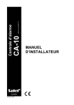
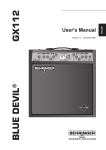
Explanations for Fig. 1:
1. The Battery cables – connect the red one to the battery terminal “+” and the black one to
the battery terminal “-“. The battery circuit is protected with a 2.5 A polymer fuse. Metal
connectors, which come with the control panel, can be used for connecting cables to the
battery (bolted connection, e.g. 17 Ah battery). Owning to that the battery cables lugs
should not be cut off.
2. The J20 pins are used for setting the battery charging current:
350 mA – pins shorted,
700 mA – pins open.
3. The RJ socket for connection of the control panel RS-232 port to the computer.
The RS-232 port is intended for programming the alarm system parameters from the
computer. For programming, a cable available in the kit designated DB9F/RJ-KPL is
required.
Notes:
• Do not short or touch the connector pins with your fingers.
• Prior to connecting the cable, the installer should first remove the electrostatic charge
e.g. touching a grounded fixture (a faucet or a heater) with the top of his hand.
• It is recommended that the cable be first connected to the control panel, and then to the
computer.
• The cable connecting the RS-232 ports may be up to twenty meters long.
4. The „DIALER” LED is on during telephone messaging by the panel, and blinks during
pulse dialing of the telephone number.
5. The J19 „RESET” pins make it possible to start the service mode without entering any
service code. This function can be disabled by the installer with software means (service
function FS131).
6. The BATTERY CHARGE LED situated next to the „J19” pins is on when the battery status
is being tested by the module and during charging of discharged battery. CA-10 tests the
presence of battery every 10 seconds and every 4 minutes it tests (for several seconds)
the battery status. During testing, the processor reduces the power supply and the loads
are powered from the battery. If the battery voltage drops down to 9.5 V, the control panel
will cut off the battery in order to prevent it from a complete discharge and damage.
14
Installer Manual
2
3
4
5
6
TIP RING T-1
R-1
1
SATEL
J20
J24
J19
RESET
SM-2
BATTERY
CHARGE
PORT
RS232
AC
AC
+
DATA CLK1 CLK2 CLK3 CLK4 COM Z1 COM Z2
18V COM OUT1 COM OUT2 COM OUT3 COM OUT4 COM KPD
Z3 COM
Z4
Z5 COM Z6
SYNTHESIZER
DIALER
COM OUT6 OUT5 +12V VOICE
350mA
700mA
Z7 COM Z8
Figure 1. Schematic view of CA-10 main board.
BOARD TERMINALS:
AC
– module power supply inputs (18 V AC ± 10%)
Z1 to Z8
– zones
OUT1 to OUT4 – programmable outputs (current-carrying capacity 2.2 A)
OUT5 to OUT6 – programmable outputs (current-carrying capacity 50 mA)
+KPD
– keypad power supply output
+12V
– power supply outputs
COM
– common
DATA
– common terminal of keypads
CLK1 to CLK4 – individual terminals of separate partition keypads
– protective terminal – ground (connect to protective circuit only)
TIP, RING
– terminals of outside telephone line
T-1, R-1
– terminals of extension telephone line (telephone set)
J18
– connector for SM-2 voice synthesizer
Electronic short-circuit and overload protection is provided for each of the outputs
OUT1-OUT4 and +KPD.
The telephone line must be of a four-wire type so that the control panel can be connected
before the other equipment (telephone, fax, etc.).
The AC terminals are intended for providing the alternating supply voltage 18 V ± 10%
from the AC/AC transformer. The control panel is fitted with an advanced pulse-type DC
power supply of high energy efficiency and operational reliability, however, its correct
functioning requires that the input voltage at the maximum load of the transformer by the
control panel does not drop below 16 V AC.
CA-10
Installer Manual
15
The control panel power supply is fitted with:
• battery status monitoring system with optional disconnection of discharged battery,
• visual signaling of the battery testing/charging process (LED indicator on the main board),
• changeover battery charging current (350 mA/700 mA).
The stabilized voltage of the control panel power supply is 13.6–13.8 V and is factory set.
Attention should be paid so as not to cause overloading of the control panel power supply in
the alarm system. It is advisable to make a load balance for the power supply. The total
current inputs for the consumers (detectors, keypads) and the battery charging current may
not exceed the power supply capacity. In case of a higher electric power demand,
an additional power supply can be used for some of the security system consumers
(e.g. APS-15, APS-30 manufactured by SATEL). Table 1 (at the end of this manual) shows
an example of estimated balance of current consumption by the system, and an example of
battery selection.
The CA-10 main board can be connected to an electric shock protection circuit (grounding).
The protective cable terminal is designated by the
symbol.
The „neutral” wire of the 230 V AC mains supply must not be connected to the
grounding terminal. If the facility has no separate electric shock protection
circuit, this terminal must be left free.
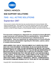
BEND ASIDE
BEND ASIDE
The CA-10 control panel should be installed in an enclosed space with normal humidity of air.
The space should be fitted with an available permanent (not detachable) 230 V power supply
circuit with protective grounding.
The control panel can be mounted in the CA-10 OBU housing (this
housing comprises a transformer designed for operation with the
control panel power supply), which permits installation of a battery with
17 Ah capacity. Before the housing is secured to the base, it is
necessary to mount inside the housing plastic distance plugs, which are
intended for subsequent installation of the main board.
In case the plugs tend to slip out, the catches fixing the plug in the
housing need to be slightly bent aside (Figure 2). When inserting the
plug, press the central part of the head firmly in so that it is blocked in
the housing hole. It is advisable to make sure that the plug, when
PRESS IN
pressed, does not slip out from the opening. During installation of the
Figure 2.
housing, be careful so as not to damage the wires which will be passed
through the hole in its back panel.
When the housing is secured, you can install the control panel main board and proceed to
making the connections.
IMPORTANT: Do not connect the mains power supply and the battery, until all the remaining
connections are completed.
The control panel is power supplied from 230 V AC mains. Negligence or wrong
connection may result in electric shock and pose a threat to life!
Therefore, be particularly careful when hooking up the control panel. In the
process of installation and connection of the control panel, the cable to be used
for mains supply must not be alive!
Connection of keypads
The keypad is designed to operate indoors in normal humidity. It should be mounted straight
on a flat surface. The spring provided on the tamper contact must adhere to the base so that
the contact will open at an attempt to tear the keypad off the wall.
16
Installer Manual
SATEL
The control panel can operate both with LCD and LED keypads in any configuration.
Notes:
• We recommend keypad CA-10 LED-S v1.2 or newer to be used, because older keypads
LED S may work incorrect with keypad LCD v3.08 and next version (it regards to the
CA-10 KLED-M keypads, which were produced earlier, as well).
• Only zone expanders with version 2 are allowed (label dated February 1998 or later).
• The LCD display is fragile. It can be broken if the keypad is dropped to the floor!
● After power-up of the KLED-S keypad, and when the control panel quits the service mode,
the keypad will remain disabled and will not react to pressing any keys for 5 seconds.
During that time the system settings are being read, and the keypad backlight is blinking
with a high frequency. Simultaneously, the keypad restores the automatic mode of keypad
illumination. The mode can be changed with the user function by holding down the key [9].
The keypads should be connected to the control panel connectors COM, +KPD, DATA,
CLK1, CLK2, CLK3, CLK4. The connectors COM, +KPD and DATA are common for all
partitions, while the connectors CLK1, CLK2, CLK3 and CLK4 determine the partition the
keypad belongs to. Where the system will be operated with less than 4 keypads, they should
be connected starting from the CLK1.
The keypads should not be connected in parallel to one CLK signal (one partition – two
keypads). It applies to all LCD keypads, as well as the CA-10 KLED-S keypads. The only
exception are the CA-10 KLED keypads, which may be connected in parallel.
Each keypad should be connected with a separate cable. The distance between the keypad
and the panel can be up to 200 m. Unscreened cables are recommended to be used for
connecting the keypads.
It is recommended to use an untwisted unshielded cable 8x0,5 mm2 (do not use twisted pair
cables). With recommended cable, the following distances between keypad and control panel
may be used to ensure appropriate power supply:
№ of cable cores
LCD keypad
LED keypad
2x1
2x1
2x1
2x1
Distance
Connection
up to 50 m
Power supply & ground
CLK & DATA signals
50–100 m
Power supply & ground
CLK & DATA signals
2x2
2x1
2x1
2x1
100–200 m
Power supply & ground
CLK & DATA signals
2x4
2x1
2x1
2x1
The keypads may be power supplied from the +KPD panel connector only. This output
can also be used for power supply of the keypad connected detectors.
As the LCD keypad current consumption is larger than that of the LED keypad (particularly
with active illumination of the keypad and display), it is important that resistance of the power
supply and ground lead-ins be taken into account when planning the cabling installation.
Caution: The supply voltage measured across the terminal block of LCD keypad with active
backlighting should not be less than 11 V.
The keypad tamper contact has no connection with the system anti-tampering circuit. Its state
is defined by the control panel, based on the data received from the keypad. When the
control panel is in the service mode, the tamper contact is not controlled.
CA-10
Installer Manual
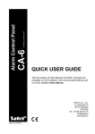
Z2 COM Z1
17
DESCRIPTION OF
TERMINALS
KPD CLK DTA
KEYPAD
PANEL
KPD
DTA
+KPD
DATA
CLK1
or CLK2
or CLK3
or CLK4
COM
CLK
COM
D
C
Z1 – to detector
Z2 – to detector
B
Additional
system zones
A
keypad adress
jumpers
tamper contact
buzzer
Figure 3. View of the CA-10 KLED-S keypad board.
keypad address
jumpers
tamper contact
D C B A
tamper contact
keypad backlight
jumper
RS-232
+KPD CLK DATA Z1 COM Z2
+KPD CLK DATA Z1 COM Z2
Figure 4. View of the CA-10 KLED
keypad board.
Figure 5. View of the CA-10 KLCD
keypad board.
The keypad Z1 and Z2 connectors permit connecting any detectors. They are supported by
the control panel in the same way as the main board zone inputs. The Z1 connector, partition
1 keypad, is recognized by the panel as zone 9, the Z2 connector, partition 1 keypad – as
zone 10, etc. (see: fig. 7) Thus, with four keypads, the control panel has 16 zones.
Alternately, a lower number of keypads and a zone expander can be used.
18
Installer Manual
SATEL
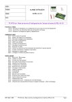
COM CLK DTA KPD
tamper contact
RS-232
Z1
Z2
buzzer
Figure 6. View of the CA-10 KLCD-L keypad board. The CA-10 KLCD-S
board only differs in its outside dimension.
COM +KPD DATA CLK1 CKL2 CLK3 CKL4
Control panel main board
zone 9
zone 10
Partition 1
+KPD CLK DATA Z1
COM
zone 11
Z2
keypad
zone 12
Partition 2
+KPD CLK DATA Z1
COM
zone 13
Z2
keypad
zone 14
Partition 3
+KPD CLK DATA Z1
COM
Z2
keypad
Figure 7. Connection of three keypads to the control panel.
CA-10
Installer Manual
19
Setting keypad addresses
The address is keypad's additional tamper protection. A different (arbitrary) address
should be set in each keypad. To set an address in LED keypad, put jumpers on
corresponding pairs of the ABCD pins (see figures: 3, 4 and description of the service
function FS111). In LCD keypad, the address must be programmed. The programming
consists in entering four digits in binary code (by analogy with the LED keypads: 1=pins
shorted, 0=pins open). The control panel does not support LED keypads in which either all
jumpers or no jumpers are set, as well as LCD keypads in which the address 0000 or 1111
has been programmed. The address is stored in the panel EEPROM (non-volatile) memory,
together with the other system parameters.
The LCD-keypad address can be changed in two ways:
1. Directly (skipping the service code):
• Disconnect the keypad power supply and the data bus wires (CLK, DATA).
• Short-circuit the CLK and DATA terminals of the keypad.
• Switch on the keypad power supply. The following text will be displayed: „Keypad
hardware address: 1001” (the default value, corresponding to the jumpers read out in
the ABCD sequence).
• Using the [0] and [1] keys, enter the proper address and then press the [#] key.
The „Address set” text will be displayed on the keypad.
• Connect the keypad to the control panel in appropriate way (CLK, DATA).
2. By means of the keypad service functions:
• Activate the control panel service mode.
• Select in turn the items in menu of displayed functions: LCD keypad; Settings;
Keypad address.
• Using the [0] and [1] keys, enter the proper address and then press the [#] key.
The keypad will display the text: „Set addresses (FS124) ? 1=Yes”.
• Press the [1] key to automatically perform the FS124 service function and save the
settings.
Note: For correct handling of the LCD keypads by the CA-10 control panel, the FS124
function must be performed on each of the LCD keypads connected to the panel.
It may turn out on starting the control panel that the keypad is not supported (no reaction to
pressing the keys). A message appears then on the LCD keypad display that there is no
communication with the control panel. This is usually because the keypad address is different
than the one programmed in the panel. Depending on whether other keypads are also
connected to the panel, or this keypad is the only one in the system, you can follow either of
the two ways:
3. Call the service mode in another keypad and start the FS124 service function, which will
result in correct keypad addresses being automatically read out by the control panel.
In this case, remember to start the FS124 service function in all LCD keypads connected
to the panel.
4. Enter the service mode by means of jumpers and program a correct keypad address in the
control panel (see: Starting the Control Panel).
Connection of zone expander
In order to increase the number of zones, a zone expander can be connected, instead of
a full set of keypads. It makes available the zones of keypads required for full configuration.
The expander should be connected as a next keypad. It can be used in combination with
a different number of keypads. For details regarding the connection see the expander
installation manual.
20
Installer Manual
SATEL
The LCD keypads can only interface in the alarm system with the expander version
manufactured since February 1998.
The expander address should be programmed as the address of consecutive keypads:
• second, third and fourth – if the expander is connected to CLK2;
• third and fourth – if the expander is connected to CLK3;
• fourth – if the expander is connected to CLK4.
Connection of detectors
The CA-10 can operate with any type of detectors. Each zone of the control panel can work
in the configuration:
• NC (normally closed),
• NO (normally open),
• EOL (End Of Line Resistors),
• 2EOL/NO (Double End Of Line Resistors, NO type detector),
• 2EOL/NC (Double End Of Line Resistors, NC type detector).
When the zone works in a EOL configuration, a 2.2 kΩ resistor should be used to make the
detector circuit. With 2EOL zone, the detector circuit is closed by two 1.1 kΩ resistors.
The zones of 2EOL type enable the status of detector and its tamper contact to be monitored
at the same time (see: Fig. 9).
The detectors may be power supplied from any of the electronically protected outputs (OUT1
to OUT4). The output should be programmed as the "POWER SUPPLY OUTPUT". Detectors
connected to the keypad zones can be power supplied from the +KPD output.
CA-10
Z1 COM Z2
Z3 COM Z4
Z5 COM
supply
NC
NC TMP TMP COM 12V
NC
Fig. 8. Example of connecting NC type detector to control panel (NO type detector is to be
connected in the same way).
CA-10
Installer Manual
21
CA-10
2,2k
Z1 COM Z2
NO
C
Z3 COM Z4
Z5 COM
supply
TMP TMP COM 12V
EOL/NO
Fig. 9. Example of connecting NO type detector in EOL configuration to control panel.
CA-10
2,2k
Z1 COM Z2
NC
Z3 COM Z4
Z5 COM
supply
NC TMP TMP COM 12V
EOL/NC
Fig. 10. Example of connecting NC type detector in EOL configuration to control panel.
22
Installer Manual
SATEL
CA-10
NC
1,1k
1,1k
Z1 COM Z2
Z3 COM Z4
Z5 COM
supply
NC TMP TMP COM 12V
2EOL/NC
Fig. 11. Example of connecting NC type detector in 2EOL configuration to control panel
(NO type detector is to be connected in the same way).
Figures show how the detectors should be connected to zones working in various
configurations. Separation of the detector power supply ground and the line ground makes it
possible to eliminate the harmful effect of wiring resistance. Assuming that the wire is rather
short, and only one detector is connected to it, the installation can be simplified by using one
wire for the power supply ground (GND) and the signaling ground (COM).
The NO and NC detectors in 2EOL configuration are connected in the same way, it is only
important to correctly indicate to the control panel, what type of detector is connected to the
zone input (2EOL/NO or 2EOL/NC).
Notes:
• The real system tamper circuit should also include the tamper contacts of sirens, control
panel housing (NC type of line), etc.
• For figures 8, 9 and 10 it is assumed that the zone no. 2 is a tamper line (preprogrammed
as: 24H TAMPER line).
Connection of Sirens
Figures 12 and 13 show how the sirens should be connected.
+12 V
LIMITER
2.2A
COM
OUT1
LOAD
COM
LIMITER
2.2A
OUT2
LOAD
COM
OUT3
LOAD
COM
LIMITER
2.2A
LIMITER
2.2A
LIMITER
2.2A
OUT4
COM
+KPD
LOAD
Caution: outputs OUT1, OUT2, OUT3 & OUT4 must be loaded with resistors 2.2 k Ω
Figure 12. Diagram of high-current outputs.
CA-10
Installer Manual
23
The CA-10 panel can control sirens of any kind. Each of the panel outputs can perform any of
41 different functions. Therefore, the system is very flexible and can suit almost every
application. If there are sirens installed in the system, the alarm function will have to be
assigned to corresponding outputs.
Where sirens are used that give alarm when energized, it is convenient to assign the alarm
function to one of the outputs OUT1 to OUT4. If this is the case, the "+ " of siren power
supply should be connected to the control panel respective OUT output, and the siren
"ground" – to the control panel COM connector. In this mode, even four independent sirens
can be set. It is possible e.g., after programming one output for operation during a preset
time, and the other for operation until cut off, to control the audible/visual sirens.
The outputs OUT1 to OUT4 perform monitoring for the presence of a load. For their
correct operation, the connected sirens must incorporate a parallel 2.2kΩ resistor.
If there are undesired low sounds in disconnected siren, this resistor value should be
reduced.
+Ucc
+12V
R
OUT n
COM OUT6 OUT5 +12V
power supply +12V
OUT5
OUT6
COM
ground shorting
output
-
+
12 V
load
50 mA
OUT n
P
relay output
Figure 13. Diagram of OUT5, OUT6 low-current outputs and load connection.
Where sirens with their own internal battery are employed, the OUT4 output can be used to
power the sirens, and the triggering signals can be provided by the OUT5 and/or OUT6
low-current outputs.
The OUT5 and OUT6 outputs can be used to control the relays switching on any sirens or
other equipment. The relays may be directly connected to the outputs, as shown in Figure 13.
NR2-DSC transmitter socket
8
CA-10
low-current
outputs
COM OUT6 OUT5 +12V
(PGM)
to battery „+”
15
(TAKT)
14
13
12
fuse
250 V/2 A
to main board AC terminal
2
9
1
DB-15
to COM terminal (next to OUT1 terminal)
Figure 14. Connection of NR2-DSC controlled transmitter, made by NOKTON.
24
Installer Manual
SATEL
The OUT4 and OUT5 outputs can also be used to control the NOKTON NR2-DSC radio
monitoring transmitter (NEMROD system – format PC16OUT). In such a case it is necessary
to change the operating mode of these outputs by activating a suitable option in the service
function FS5. During operation with the NOKTON transmitter, the outputs are used for
transmitting a number of data on the control panel state (zone alarms, fire alarms, troubles,
armed mode, etc.) and do not perform functions programmed with the standard service
functions.
When hooking up any equipment with a considerable current consumption (e.g.
a radio monitoring transmitter) to the control panel, their "+" should be
connected to the battery "+" (a fuse is recommended on the feeder cable).
The ground must be connected to any COM contact of the control panel, but not
directly to the battery "-". Connection of the common ground to the battery "-"
causes incorrect operation of the charging current limiter and quick discharge
of the battery but can even damage the control panel.
Connections of telephone line
If the control panel telephone communicator is used in the alarm system (for monitoring,
messaging or remote programming), it is necessary to connect telephone line to the control
panel. It should be led to a connector situated on the right side of the printed board. In order
to ensure proper messaging, the control panel must be directly connected to the line
(connectors designated as TIP and RING), and any other devices (telephone, telefax) – after
the control panel (connectors designated as T-1 and R-1). Such a connection will make it
possible for the control panel to fully engage the line for the time of calling, which prevents
the messaging function from being blocked by lifting the handset. Additionally, the telephones
connected after the control panel do not signal the dialing by the control panel.
Caution:
• Do not send telephone signals and alarm system signals by one multicore cable. This may
result in a damage to the system in case of a high-voltage punch-through from the
telephone line.
• Telephone terminals of the panel should be connected to PSTN lines only. Connecting to
ISDN lines may lead to damage of the equipment.
• System installer should give the necessary information on the way of connection with
telephone network to system owner.
Connection of voice synthesizer
control panel
board
ground
low-frequency signal
release
tel. line monitoring
power supply +
Figure 15. Description of SM-2 voice
synthesizer connector.
Where the function of alarm messaging with
voice announcements is used, a voice
synthesizer must be connected to the control
panel.
The CA-10 panel interfaces with the SM-2
synthesizer.
The
synthesizer
socket
(designated as: SM-2 VOICE SYNTHESIZER)
is situated on the right-hand side of the
printed board, between the telephone line
connector and the socket of OUT5, OUT6
outputs. The SM-2 synthesizer should be
directly plugged into this connector. It is fitted
with minijacks for playback of the message
and "monitoring" of the telephone line.
CA-10
Installer Manual
25
Connection of printer or computer
If a detailed documentation of events occurring in the alarm system is required, a printer must
be connected.
The printer can be connected either permanently or just for printing the event log. When the
printer is connected permanently, all the events occurring in the system are printed instantly.
The printout line includes the date, time, description and source of the event (zone number,
partition number or user number).
The control panel is designed to control printers having an RS-232 port. On the control panel
board, the RS-232 port is linked to the J24 connector (RJ socket). The control panel RS-232
port also enables the panel to be connected to the computer.
65
PANEL
PRINTER
2
COM
TXD
COM
RXD
4
DSR
DTR
5
DB9M CONNECTOR
1
2
1
RS-232 PORT
RJ SOCKET ON PCB
6
5
3
4
MEFKA
PRINTER SOCKET
MALE CONNECTORS FROM SOLDERING POINTS SIDE
Fig. 16. Connection of a printer to the control panel RS-232 port.
PANEL
COMPUTER
COM
TXD
RXD
RTS
GND
RXD
TXD
CTS
DSR
DTR
5
4
3
8
2
DB9F CONNECTOR
654 3 1
RS-232 PORT
FEMALE CONNECTORS FROM SOLDERING POINTS SIDE
RJ SOCKET ON PCB
Fig. 17. Connection of computer to the control panel RS-232 port.
The arrangement of signals and the hookup of printers or a computer to this connector are
shown in Figure 16 and 17. As a rule, the panel TXD signal is supplied to the printer or
computer RXD input, and the computer TXD signal to the panel RXD input. The printer or
26
Installer Manual
SATEL
computer notifies the panel with a DTR signal of its readiness to receive data. Lack of this
signal is reported by the panel as a trouble of the RS-232 port.
After starting the DLOAD10 proprietary program (on the included CD), selecting the
appropriate communication port (CONFIGURATION window) and activating the FS112
service function in the control panel, it is possible to program the control panel from the
computer.
Connection of power supply
The control panel is permanently connected to the mains power supply. Hence, before you
start to work on the system cabling, make yourself familiar with the electrical installation in
the facility. In order to power the control panel, select a circuit where voltage is always
present. This circuit should be protected with an appropriate fuse.
Before connecting the control panel to its power supply circuit, you must turn
off voltage in that circuit.
Description of electrical connections to the CA-10 OBU housing:
1. Connect the 230 V alternating voltage leads to the transformer terminals marked
"AC 230 V".
2. Connect the output voltage wires of the transformer secondary winding to the "AC" (~18 V)
terminals on the control panel main board.
3. Connect the wire of the PE electric shock protection circuit to the terminal block situated
next to the transformer and marked with the ground symbol
. This circuit should also be
connected to the control panel protective terminal.
Do not connect the "neutral" wire of the 230 V AC mains supply circuit to the
ground terminal. If there no separate electric shock protection circuit in the
facility, this terminal should be left free.
Control panel power-up starting procedure:
1. Connect the emergency power supply wires to the corresponding battery terminals (the
red one to the battery plus, the black one to the minus). The control panel will not start
on connecting the battery alone (without the mains power connected), however, it will
keep on working in case of the 230 V AC voltage trouble, provided it was already started.
2. Switch on the 230 V AC mains supply – the control panel start follows.
Connection of the power supplies in the prescribed order will permit correct functioning of the
power supply unit and the control panel electronic safety devices, thus avoiding damage to
the security system elements caused by possible installation faults.
Note: If it is necessary to completely disconnect the control panel power supply, the 230 V
alternating voltage should be disconnected first, then the battery. Re-connection of the
power supply is to be performed in the above mentioned order (the battery first, then
the 230 V alternating voltage).
As the control panel has no isolating switch to disconnect the mains supply,
it is important that the owner or the user of the security system be informed on
how the system is to be disconnected from the mains (e.g. by indicating the fuse
which protects the control panel supply circuit).
Starting the control panel
When all electrical connections are made and checked for correctness, you can proceed to
starting the system. It is recommended to begin the work with the control panel with no sirens
connected, as the load can exceed capacity of the power supply unit, thus making start of the
control panel impossible. The sirens can be connected after programming parameters of the
realized alarm system is completed.
CA-10
Installer Manual
27
If the control panel operates with one keypad, having a default address (1001 – jumpers on
pins „A” and „D”), then, after the power is switched on, the keypad will report readiness for
work with four short beeps followed by a long one.
Note: The control panel with default settings will not support a keypad connected to the
CLK1 signal if the default address (1001) has been changed in that keypad.
If the control panel is alarming after power-up, clear the alarm by means of the user access
code (default master code for partition 1: [1][2][3][4]) and proceed to programming
parameters in the service mode.
Upon entering the default service code [1][2][3][4][5] and confirming it with the [#] key, the
control panel will enter the service mode. The
[ARMED] LEDs will be
[ALARM] and
blinking alternately. Now, you can proceed to programming the control panel.
Note: For the safety reasons it is recommended that the keypad default address be
changed. Having done the changes, you must run the FS124 function.
If the system includes more keypads or where the zone expander is installed, the control
panel will not support any devices connected to the signals CLK2, CLK3, CLK4 until their
addresses have been programmed in the control panel memory.
Hardware access to the service mode
If the panel does not „see” the keypad when the power is on, and does not respond to the
keystrokes (access code entry), or keeps on alarming, it is necessary to carry out the
procedure of hardware access to the service mode. This allow to program of the
keypad/expander addresses before the normal operating mode is restored. In the other case,
the control panel will start alarming right after the power-up because it has detected the
keypad tampering.
To start the service mode by means of jumpers follow the procedure below:
1. Disconnect in turn the mains supply and the emergency supply.
2. Check the keypad address jumpers and tamper contacts for correct settings.
3. Put a jumper on the control panel RESET pins (J19).
4. Connect in turn the emergency supply and the mains supply.
5. After the keypad beep, remove the jumper from the RESET pins (J19). The operation
will activate the service mode in partition 1 keypad. This will be signaled by the
keypads with four short and one long beeps.
6. Call the service function FS124. The function automatically reads the keypad address and
prepares the control panel for work in a new configuration.
Note: If LCD keypads are installed in the alarm system, call the FS-124 service function
in each LCD keypad. When activated from the LCD keypad, this function automatically
performs additional configuring operations and its activation in each LCD keypad is
necessary for proper operation of the system.
7. To make sure that all the settings are in accordance with the default values, you can
perform the service functions FS107, FS108 and FS110.
Having completed the procedure, exit the service mode using the function FS0 and activate
the service mode again – this time from the keypad – by entering the default access code
[1][2][3][4][5] confirmed with the [#] key.
If the control panel has re-entered the service mode, it means that its functioning is correct
and that you may proceed with further installation of the system (connection of sensors,
sirens, establishing communication with a computer, if required) and programming of all
necessary parameters.
28
Installer Manual
SATEL
If the described procedure is unsuccessful, the option of hardware access to the service
mode must have been disabled in the control panel by software means. If this is the case,
it is necessary to carry out another procedure which would enable the control panel and
restore the default settings:
1. Disconnect in turn the mains supply and the emergency supply.
2. Set a jumper on J19 RESET pins.
3. Connect in turn the emergency supply and the mains supply.
4. Wait about 60 seconds (±5 sec.) and remove the jumper.
5. Enter from keypad the code: [1][2][3][4][5] (the code should be entered within 15 seconds)
and confirm by pressing the [#] or [*] key.
Programming the control panel from the computer
Programming the control panel from the computer via the RS-232 port should be initiated by
calling the service mode and the FS112 communication function in the control panel.
Provision is also made for starting communication without calling the function FS112 – which
is convenient if the control panel is already installed on the site and there is no keypad in the
vicinity. In order to start communication without the use of keypad do the following:
1. Disconnect in turn the mains supply and the emergency supply.
2. Connect the cable to RS-232 ports in control panel and computer (Fig. 17).
3. Start the DLOAD10 program in the computer.
4. Select in the program the communication port to which the cable is connected.
5. Select in turn the following functions from the program menu: Communication; Local
connection with...; CA10 (RS-232, without the use of keypad).
6. Follow the messages displayed by the program.
ACTIVATING SELECTED FUNCTIONS
Performance of some functions of the control panel requires that a few to more than a dozen
parameters be programmed simultaneously. This section contains detailed information on
how to program such functions as: telephone messaging, monitoring and downloading.
Guard control function
The functioning of the guard control function consists in automatically checking that the,
so-called, guard code is entered on the keypad with a preset frequency. The entry of the
code is saved in the log event, and so is the trouble to enter the code after a preset period of
time, which can be signaled on an output which has the proper function. These events can be
reported to the monitoring station.
To activate the function you must:
• program the guard code – in the user function 2 (creating new user) a code with authority
level 5 (instead of the guard code, the user function 7 can also be used – activation of the
„switch MONO" output)
• set a suitable timer to perform the „partition monitoring” function (FS106)
• program the timer control time (functions FS102–FS105, depending on the partition).
Telephone messaging – alarm reporting
The telephone messaging function requires that the following be programmed:
• FS5, FS131 – activate the “telephone messaging” option, set the “dialing system” option
as required by the telephone exchange,
CA-10
•
•
•
Installer Manual
29
FS87 to FS94 – enter at least one telephone number,
FS95 – define the partitions from which alarms are to be reported to the telephone
numbers programmed in functions FS87–FS90,
FS100 – number of telephone messaging queues higher than zero and number of redials
in a queue.
Note: You should also program in FS95 what kind of message will be sent – if no message is
selected for the pager, the control panel will notify with a voice message from the voice
synthesizer.
When the above parameters are correctly programmed and the alarm is triggered, the onboard LED (designated as „DIALER”) should go on, which indicates that the panel has
started telephone messaging (with pulse dialing the LED is blinking). It is recommended to
test the messaging. To this purpose, use the ordinary headset connected to the „telephone
line monitoring” jack in the SM-2 synthesizer (parallel connection of a telephone set to
„monitor” the communication will interfere with the messaging operation). The telephone
messaging will start immediately after triggering the alarm. Alarm clearing will interrupt the
telephone messaging.
Typical problems with starting the voice messaging:
• control panel takes no attempts to call – not all of the above mentioned items were
programmed;
• control panel goes on line but fails to dial – no dial tone or a non-standard dial tone
from the telephone exchange – find out the cause of missing signal or deactivate the dial
tone test option in FS5 if the signal is non-standard;
• control panel establishes connection, but sends no voice message – wrongly
programmed FS95 – messaging to pager selected, but not voice message from the
synthesizer;
• control panel establishes connection, sends a message too early or too late – the
control panel recognizes answering the call on the basis of sound signals on the telephone
line, with permissible message sending delay up to 4 seconds from lifting the handset – if
commutation signals on the telephone line are non-standard or there is strong interference
(clicks, hum), the panel automatic equipment may not function properly – then you can
extend the message by activating the “double message” option in FS5 or deactivate the
call answer recognition option;
• control panel reports the alarm more times than the preprogrammed number of
queues – the control panel recognizes answering the call on the basis of a callback signal
– if the user lifts the handset too quickly (during the first ring), the control panel may
disregard the message and call again.
Reporting to telephone monitoring station
The monitoring station operator should provide the installer with the data necessary for the
monitoring software. These are:
• monitoring station telephone numbers;
• transmission format or a list of available formats;
• alarm system identifier (facility number – one or more for detailed reporting from a big
system);
• list of event codes.
In order to start monitoring, the following items should be programmed:
• FS43 – monitoring station telephone number – if there are two numbers or two
stations, the other number should also be programmed in FS44.
30
•
•
•
•
•
•
Installer Manual
SATEL
FS45, FS46 – station transmission formats – in case of a multi-format station, select
format which is as fast as possible (e.g. Ademco Express or Radionics 2300 with parity).
FS47 – monitoring options.
FS48 to FS59 – monitoring stations identifiers, an identifier should have 3 or 4 nonzero characters (characters from “1” to “F”, “0” – no character), some stations use
identifiers composed from digits from 0 to 9 – then character “A” is to be programmed
instead of digit “0” (e.g. “A1A2” instead of “0102”).
At least three identifiers should be programmed (can be identical):
− zone identifier,
− partition identifier,
− system event identifier.
FS60 to FS66 & FS69 to FS72, FS81, FS82, FS126 – event codes according to the list
from the monitoring station operator, the codes can be one-digit (the other character
being 0) or two-digit – as required by the station, the codes with inappropriate length may
block communication with the station.
if reporting with event sorting to both stations has been selected in the options, events
assignment should be programmed in the functions FS67–FS68, FS73–FS80, FS83,
FS84.
FS5 – activate the option “Monitoring” after the above items have been programmed.
Typical problems with starting the monitoring:
• Control panel takes no attempts to call – not all of the above mentioned items have
been programmed – the control panel will not call the monitoring station if the
programmed data do not allow sending a correct transmission to the station because of
e.g. missing telephone number, identifier being shorter than 3 non-zero characters,
missing event code, etc.
• Problems with dialing – no dial tone or a non-standard dial tone from the telephone
exchange – find out the cause of missing signal or disable the dial tone test option in
FS5 if the signal is non-standard.
• Control panel sends no codes when connected to the station – wrongly selected
format or low quality of telephone connection (the panel does not “understand” the
station dial tone).
• Station does not receive or acknowledge the codes sent by the panel – wrongly
selected format, inadequate identifier length (3 characters, while the station requires 4),
inadequate event code length (1 character, while the station requires 2) or low quality of
telephone connection.
• Control panel does not send codes of some events, despite of the codes being
properly entered – identifier of the particular group of events is missing, e.g., if the
partition 1 identifier is missing, no reports on this partition arming/disarming will be sent.
• Control panel automatically changes the option „transmission to Station 1 or to
Station 2” into transmission to one station only – if with this monitoring option
selected the number of identifiers for Station 1 and Station 2 is different (there are
codes which have an identifier for one station, but not for the other), the panel cannot
report to both stations in the „Station 1 or Station 2” mode and will change the option for
transmission to the station which has a larger number of identifiers.
Note: For the Ademco Express transmission format the identifier „0000” is correct (sending
"zero" is possible), while for the other formats it means no identifier ("zero" is not sent).
A headset connected to the "telephone line monitoring" jack in the SM-2 synthesizer can be
helpful in analyzing the problems with communication to the monitoring station.
CA-10
Installer Manual
31
Connection with the station is established in the following way:
• the station answers the call and sends the, so-called, handshake signal (one or a few in
sequence if the station supports several transmission formats),
• the control panel recognizes the station handshake signal and if it matches the
programmed transmission format, the control panel answers by sending identifier and
event code in appropriate tones (once or twice, depending on the selected format) – in the
headset connected to the line monitoring jack, these sounds are much louder than the
monitoring station signals,
• if the station receives information, it will acknowledge it with the same signal as the
handshake,
• the panel disconnects or sends next codes if there still are some other events to be
reported to the station.
The most common monitoring problems result from inaccurate information on the
transmission formats supported by the given station (e.g., ambiguous names of the formats),
errors in the data entered into the control panel, as well as poor quality of the telephone
connections. Often only by “monitoring” the course of communication you are able to find the
cause of a problem.
Note: Some stations do not acknowledge reception of the event code if it has another format
(e.g., 4/1 instead of the required 4/2). If this is the case, the control panel will repeat its
attempts to establish communication, while telephones in the facility will be
disconnected – the costs of such connections may be very high. For this reason, it is
recommended that all the programmed codes be very carefully checked. It is possible
to activate the options 7 and 8 in FS-47, which makes the panel omit the codes
unacknowledged in 16 consecutive retries. Problems of this type do not occur in
professional, multi-format monitoring stations (including the Satel STAM-1).
Downloading – telephone communication with the computer
Telephone communication with the computer requires a modem. The modem must meet two
essential conditions:
1. enable operation in the transmission format UTI V.21 (CCITT V.21) or BELL 103
(operation at a rate of 300Bps on telephone line),
2. permit operation to be configured only in one of these formats (the function of automatic
format negotiating disabled).
Before starting the first connection between the computer and the control panel, appropriate
settings must be entered in the DLOAD10 program (CONFIGURATION window). Information
on the modem configuration is contained in the DLOAD10 program „HELP” file (function
activated with F1 key), topic: “COMMUNICATION” and in chapter “Program configuration for
communication with the panel” of this manual. In the case of non-standard modems, you
must refer to the modem manual for the information on configuration procedures.
Modem initialization
The program initializes the modem after the „MODEM” item is selected from the
„COMMUNICATION” menu. In case of any trouble, the program will display one of the two
messages:
• MODEM NOT RESPONDING – which means a technical problem with communication
with the modem, e.g. an incorrect COM port number, conflict with the Windows system
drivers;
• BAD COMMAND – wrong command initializing the modem.
Correct initialization of the modem does not mean it is properly configured to work with the
control panel. The first initializing commands, as suggested in the program, are sufficient
32
Installer Manual
SATEL
for a correct operation of most older-generation modems (i.e. modems with a maximum
speed of 2400 Bps). The fast modems of a new generation require some extra commands
being added to limit their operation speed.
Remote communication procedure:
• program in the control panel:
− FS2: control panel identifier by which the program recognizes the alarm system
− FS3: computer identifier by which the control panel recognizes the computer
authorized to establish connection
− FS4: computer telephone number (which is not necessary)
− FS5: “external DOWNLOADING” option, “double call” option (any setting) and the
FS101 – number of rings before answer – if communication is to be initiated from the
computer
• start the DLOAD10 program, select the CA-10 control panel and its version, e.g. by
opening the data of such a panel and select the “MODEM” item from the
„COMMUNICATION” menu.
Note: The communication identifiers and the „double call” option settings must be identical
in the control panel and in the alarm system computer data.
Telephone connection with the control panel will be set up automatically after selecting any
communication command in the program (Read, Write, Event log read, ON-LINE mode).
You can also start communication from the panel with the user function 0.
Telephone communication error messages:
• “modem not responding” – the modem has not acknowledged the dialed number
(a rare case, usually a problem caused by modem hardware or e.g. missing the “V1”
initializing command),
• “panel not responding”, “no panel's carrier”, “no panel's initial greeting”
“insufficient line quality or bad PC's communication password!”, “panel's
communication password does not match PC data”:
− connection with the control panel was unsuccessful,
− the control panel was off hook but did not answer the modem signal because it was
much corrupted,
− the control panel was off hook but did not answer the modem signal because it was
not in the transmission format V.21 or BELL 103 (incompatible or incorrectly
configured modem),
− the control panel established connection, but the identifiers in the control panel and
computer are different – the panel disconnects,
• “connection interrupt” – the control panel stopped answering the computer signals.
Note: If the control panel answers the call but fails to establish communication and
disconnects, while the “double call” option is deactivated, it will be answering no
calls for the next 5 minutes.
Programming the LCD keypad from the computer
Programming the LCD keypad data is only possible in the local mode. You can program the
following data:
− keypad options,
− names of zones, partitions and outputs,
− message contents,
− user names.
CA-10
Installer Manual
33
Note: The names contained in the data of the first partition LCD keypad are used as
descriptions when scrolling through the event log.
In order to program the data you should:
• connect the RS-232 ports of keypad and computer with a corresponding cable (see:
DESCRIPTION OF CONTROL PANEL MAIN BOARD, point number 3 – RJ socket),
Note: For programming the LCD keypad a different cable is necessary than for
programming main board via RS-232 port. The cable for programming the LCD
keypad is available in the kit designated DB9F/RJ-KPL.
•
•
•
•
•
•
•
•
start the DLOAD10 program in the computer and select the COM port to which the cable
is connected (see: Program configuration for...),
open the file with alarm system data,
open the LCD keypads window and select the corresponding keypad (tabs:
LCD 1...LCD 4),
start the data readout by clicking on the Read field on the right-hand side of open window
(the correct readout operation is confirmed by the status bar indicator at the bottom of the
window),
enter the data in the corresponding fields of the computer screen,
save the data in the keypad memory by clicking on the Write field just below the Read
field,
disconnect the cable from the keypad RS-232 port,
repeat the programming operation for the other LCD keypads in the system.
REMOTE PROGRAMMING – DLOAD10
The DLOAD10 program delivered with the control panel is designed for programming the
CA-5, CA-6 and CA-10 panels, as well as the RX2K, RX4K radio controllers, GSM-4 and
GSM LT-1 module and ACU-100 wireless system controller from the computer. Additionally,
the program makes it possible to create documentation of alarm systems, sets of settings for
various configurations ("patterns" which facilitate the programming of new systems), event
sets for each system, as well as to remotely operate the control panel in the same way as
with the keypads.
The program is designed for IBM PC/AT compatible computers. It works in any computer
hardware configuration in the WINDOWS (9x/ME/2000/XP) environment. It is recommended
that the program be installed on the computer hard disk.
The control panel communicates with the computer through the RS-232 interface or via the
telephone line. For telephone communication with the panel, the program uses a modem
controlled by one of the COM ports (internal or external), compatible with the HAYES "AT
Command" standard. Communication with the control panel is possible in the CCITT V.21 or
BELL 103 standard (at 300 Bps). As the control panel transmits data only with a speed of
300 bauds, the modem must support this speed of operation.
Usually a suitable modem configuration is necessary – disabling the transmission
standard negotiating function and forcing the transmission speed of 300 Bps.
In order to install the program, run the D10setup.exe program from the CD, which is
delivered with the control panel. The installation completed, start the program. Access to the
program is protected with an access code. After installation, the code is 1234 and can be
changed to any sequence of 16 alphanumeric characters. As long as it has its factory form,
you can start the program (with default code 1234) by pressing the „ENTER” key (no access
code need to be entered).
34
Installer Manual
SATEL
Having started the program, configure and initialize the work of RS-232 port or modem by
means of which the control panel will be programmed. By default, the program opens
a window which enables the CA-10 panel to be programmed. Your next step can be starting
the connection (either remote or local).
A HELP system is provided which facilitates operating of the program, as well as the very
programming of control panel parameters. The system is accessible from the „HELP” menu,
or by pressing the F1 key on computer keyboard. To get an instant access to more detailed
information, first select the required element in the program window (by moving the mouse
pointer to and left-clicking on it), and then press the F1 key.
Program configuration for communication with the panel
Figure 18. Dialog boxes in DLOAD10 program.
CA-10
Installer Manual
35
In order to begin configuration, click on the
icon to open the „Configuration” window.
The „Port RS-232” tab permits selecting the computer port number in the case of
direct programming through the panel RS port. If the control panel is being
programmed by means of the modem, select the „Modem” tab and click on the „Details”
button.
After opening the „Modem” window, select the corresponding modem type or click on the
„! Change” button to enter data according to the documentation of your modem. Entering
a new name and initialization path, and confirming it with the „OK” button makes it possible
to add new settings to the list of modems. After clicking on the „! Change” button you can
also change the communication port number and the maximum transmission rate.
The „
Test” button permits checking interaction between the modem and the program – it
opens a window containing information on modem initialization.
Having properly initialized the operation, close the configuration windows.
In order to start communication through the RS port, follow the instructions contained in
section „Programming the control panel from the computer”.
The modem communication can be started by clicking on the
icon (or selecting the
„MODEM” command from the „COMMUNICATION” menu). The program will open a dialog
box enabling connection to be established and will prompt the further course of action.
For details see the section „Remote programming – DOWNLOADING”.
The type of control panel is recognized automatically on establishing connection, or can be
selected through the “File” menu.
) after the communication has
Calling the function of reading the control panel data (icon
been established may speed up the subsequent process of saving the changes made in the
control panel programming.
DEFAULT SETTINGS
Control panel configuration (restore with FS 107 function):
• one partition including all the available zones (Z1 to Z10),
• zone 1 (Z1) – ENTRY/EXIT function, EOL (End Of Line Resistors),
• zones 2 to 8 (Z2 ... Z8), 9, 10 (Z1 & Z2 in partition 1 keypad) – INSTANT function, EOL,
• zones 11 to 16 – not used,
• sensitivity of all zones – 0.48 sec.,
• PRIORITY option activated for all zones (FS 27, first option),
• other zone options deactivated, detector operation testing disabled,
• output OUT1 – BURGLARY ALARM function, operation time equal to global time,
polarity +12V, assigned to all zones (audible signaling),
• output OUT2 – BURGLARY ALARM function, operation time before cleared, polarity
+12V, assigned to all zones (visual signaling),
• output OUT3 – detectors power supply,
• output OUT4 – not used,
• output OUT5 – READY STATUS function (for all zones),
• output OUT6 – telephone usage status function (OUT5 & OUT6 output functions are
connected with testing the panel during production process),
36
Installer Manual
SATEL
• partition 1 keypad displays all zones available, no automatic zone bypasses, all
functions available, disabled audible trouble signaling only,
• most of the options deactivated (telephone messaging, monitoring, telephone
answering, etc.; tonal dialing and reporting suspending active),
• all data related to monitoring and telephone messaging erased,
• pager station signal parameters in accordance with the POLPAGER system,
• counting times of counters – 30 seconds; counter values – 0,
• global times:
− entry delay – 60 seconds,
− exit delay – 30 seconds,
− keypad alarm duration – 60 seconds.
Communication identifiers (restore identifiers with FS109 function):
• control panel identifier
|2|1|4|3|6|5|
• computer identifier
|6|5|8|7|0|9|
Control panel access codes (restore codes with FS110 function):
• service code
[1][2][3][4][5]
• master code partition 1 (A)
[1][2][3][4]
• master code partition 2 (B)
[2][3][4][5]
• master code partition 3 (C)
[3][4][5][6]
• master code partition 4 (D)
[4][5][6][7]
CA-10
Installer Manual
37
TECHNICAL DATA
Control panel
Main board supply voltage ............................................................................. AC 18 V ± 10%
Control panel DC power supply nominal voltage ......................................................DC 12 V
Main board current consumption ................................................................................. 95 mA
Outputs OUT1 to OUT4 and +KPD current-carrying capacity ....................................... 2.2 A
Outputs OUT5 & OUT6 current-carrying capacity ....................................................... 50 mA
Total capacity of power supply ...................................................................................... 1,7 A
Recommended standby battery supply ................................................................ 12V/17 Ah
Battery charging current (changeover) ............................................................... 350/700 mA
Battery cut-off voltage .................................................................................................. 10,5 V
Battery protection .................................................................................... polymer fuse 2.5 A
Operational temperature range........................................................................... -10…+55ºC
Housing dimensions ....................................................................................305x305x85 mm
Spacing of mainboard mounting holes ......................................................... 162.6x91.5 mm
Weight .......................................................................................................................... 223 g
LED keypads
Supply voltage .............................................................................................. 12 V DC ±15%
Current consumption min/max ................................................................................ 35/90 mA
Dimensions: CA-10 KLED ............................................................................. 145x78x27 mm
CA-10 KLED-S ........................................................................... 80x95x21 mm
Weight:
CA-10 KLED ............................................................................................ 154 g
CA-10 KLED-S .......................................................................................... 78 g
LCD keypads
Supply voltage ............................................................................................... 12 V DC ±15%
Current consumption min/max .............................................................................. 50/170 mA
Dimensions: CA-10 KLCD ........................................................................... 160x126x35 mm
CA-10 KLCD-L........................................................................ 145x114x29 mm
CA-10 KLCD-S ......................................................................... 115x95x25 mm
Weight:
CA-10 KLCD ............................................................................................ 317 g
CA-10 KLCD-L......................................................................................... 217 g
CA-10 KLCD-S ........................................................................................ 141 g
38
Installer Manual
SATEL
Table 1. Example of panel power supply load estimation and battery selection.
No. Loads
Max current
Mean current consumption
1
Main board CA-10
95 mA
95 mA
2
Keypads (2 LCD + 2 LED)
520 mA
200 mA
3
Outputs OUT1...OUT3
3 x 2.2 A **
2A
4
Output OUT 4 (detectors 15 pcs.*)
15 x 20 mA
15 x 20 mA
5
Outputs OUT 5...OUT 6
2 x 50 mA
50 mA
6
Battery charging current
700 mA
-
Total max current consumption by the system with ∑I = 95 mA +520 mA+300 mA+100 mA+700 mA
no alarm signaling
=1715 mA
Battery selection based on max. and mean
current consumption by the system, assumed
duration of power trouble 12 h, assumed 1 alarm
with 15 min (0.25 h) duration of signaling
∑AMax=1.25x(0,095x12+0.52x12+6.6x0.25+0.3x12+0.1x12)
=1.25 x 13,83 ≈ 17,29 mA
∑AAv= 1.25x(0,095x12+0.2x12+4x0.25+0.3x12+0.05x12)
=1.25 x 8,74 ≈ 10,93 Ah
Recommended standby power supply: battery 12 V/17 Ah
* Assumed current consumption by a single detector 20 mA.
** In case, where the capacity of the power supply is exceeded, the current is supplied by battery.
Notes:
• The control panel power supply unit has been designed for work with lead batteries or
other batteries with a similar charging curve (European Directives 91/157/EEC and
83/86/EEC).
• It is impermissible to connect a fully discharged battery (voltage on terminals without
a load less than 11 V) to the alarm panel. To avoid hardware damage, fully discharged or
never used battery should be charged initially using proper charger.
ATTENTION!
An efficient security system does not prevent burglary, assault or fire from happening,
however it diminishes the risk that such a situation will cause no alarm or notification.
Therefore, the SATEL Company recommends that operation of the whole security
system be regularly tested.
PORT
RS232
J24
battery charging
current (changeover)
high-current
programmable outputs
description of sirens
connection
on p. 22
description
on p. 13, 27
Z4
Z5 COM Z6
Z7 COM Z8
programmable zones description of detectors
connection on p. 20
Z3 COM
CA-10 Control Panel connection diagram (detailed description of main board terminals – see p. 13).
keypads terminals
description of keypads
connection on p. 15 – 18
BATTERY
CHARGE
RESET
J19
description of printer or
computer connection on p. 25
DIALER
AC
+
DATA CLK1 CLK2 CLK3 CLK4 COM Z1 COM Z2
18V COM OUT1 COM OUT2 COM OUT3 COM OUT4 COM KPD
transformer 18 V AC ± 10%
battery leads
12 V/17 Ah
AC
350mA
700mA
J20
R-1
TIP RING T-1
SM-2
VOICE
SYNTHESIZER
COM OUT6 OUT5 +12V
low-current programmable
outputs
description of use on p. 23
power supply outputs
voice synthesizer
description of
connection on p. 24
outside telephone
line
extension
telephone line
History of the manual updates.
Described in the table below are changes as compared with the manual for the CA-10 control panel with
firmware in version 4.10.
Date
July
2007
Version
Introduced changes
5.11
The control panel in version 5.11 supports the keypads with program version v3.12 or
later (p. 9).
The RS-232 port socket has been changed. A new cable is necessary for programming
the control panel from computer (p. 13).
Some of the figures have been changed, e.g. the detectors connection figure (p. 20).
SATEL sp. z o.o.
ul. Schuberta 79
80-172 Gdansk
POLAND
tel. + 48 58 320 94 00
[email protected]
www.satel.eu