1
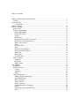
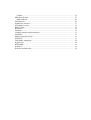
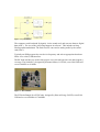
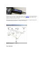
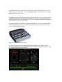
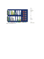
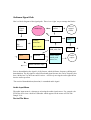
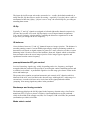
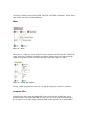
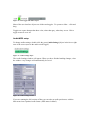
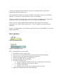
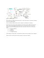
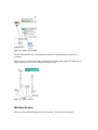
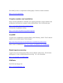
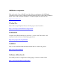
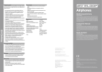
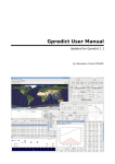
Software Defined Radio in Max/MSP
A software defined radio receiver.
Works with the Soft66lc2 (500 KHz to 30 MHz) and the FUNCubeDongle Pro (64 MHz
to 1.7 GHz)
Features include:
•
•
•
•
•
•
•
•
Support for generic IQ devices and files
SSB, AM, FM, and FMW
AGC, Notch/Peak filter, and Noise filters
Midi control-surface support
iPad control-surface support via touchOSC
Memory store/recall
Scanner interface
Synthesizer interface
Runs in Mac OS and Windows
Requires Max/MSP 5+ (distributed by Cycling74)
(iPad screens require touchOSC app)
For downloads, support, and tutorials: http://zerokidz.com/radio
Figure 1 - A software defined radio receiver in Max/MSP
Credits:
This project is derived from the work of the following developers:
•
•
•
•
•
•
•
•
Kazunori Miura, JA7TDO - Soft66lc2 hardware/software design
Thomas Horsten - Linux soft66add control software
Thomas Robin-Couerrier - PPC externals, conversion & testing
Howard Long, G6LVB - FUNCube hardware/software design
Alexandru Csete, OZ9AEC - QTHid FUNCube control software
Mario Lorenz, DL5MLO - FUNCube control software
David Pello, EA1IDZ - Linux FUNCube command line control software.
Joseph Zicarelli, KB1URI - Project design and testing.
Thank you.
Tom Zicarelli, KA1IS - November 19, 2011
Table of Contents
Software Defined Radio in Max/MSP ................................................................................ 1
Credits:............................................................................................................................ 2
System Design .................................................................................................................... 5
User Interface.............................................................................................................. 7
Software Design................................................................................................................ 11
Software Design................................................................................................................ 11
Source code ................................................................................................................... 11
Software Signal Path..................................................................................................... 12
Audio Input Menu..................................................................................................... 12
Device/File Menu...................................................................................................... 12
IQ flip........................................................................................................................ 13
IQ balancer................................................................................................................ 13
preamp/attenuator/RF gain control ........................................................................... 13
Bandscope and tuning controls ................................................................................. 13
Mode select control................................................................................................... 13
Mixer......................................................................................................................... 14
Lowpass filter............................................................................................................ 14
AGC .......................................................................................................................... 15
Detector (demodulator)............................................................................................. 15
Audio Notch/Peak filters........................................................................................... 16
Hum filter.................................................................................................................. 16
Noise filter ................................................................................................................ 16
Lowpass filter............................................................................................................ 17
Device control............................................................................................................... 17
Soft66lc2 ................................................................................................................... 17
FUNCube .................................................................................................................. 17
MIDI control ............................................................................................................. 17
User Manual...................................................................................................................... 19
Installation..................................................................................................................... 19
Hardware Setup............................................................................................................. 19
Cables........................................................................................................................ 19
Antennas ................................................................................................................... 20
Audio......................................................................................................................... 20
Using the program......................................................................................................... 20
Sliders, buttons, and toggles ..................................................................................... 20
Audio/MIDI setup..................................................................................................... 21
Basic operation.......................................................................................................... 22
Audio on/off.............................................................................................................. 23
Memory presets......................................................................................................... 23
Controlling Device Frequency.................................................................................. 24
Filters ........................................................................................................................ 24
Tuning tips and troubleshooting ............................................................................... 24
AGC .......................................................................................................................... 25
Scanner...................................................................................................................... 25
Midi Specification......................................................................................................... 27
Midi feedback ........................................................................................................... 29
iPad Interface ................................................................................................................ 29
Synthesizer interface ..................................................................................................... 31
[led] display screen ....................................................................................................... 31
What’s Next? ................................................................................................................ 32
References..................................................................................................................... 32
Antennas ....................................................................................................................... 32
Complex numbers and modulation ............................................................................... 33
CuteSDR ....................................................................................................................... 33
Digital signal processing............................................................................................... 33
FUNCube ...................................................................................................................... 33
GNURadio companion.................................................................................................. 34
IQ data files................................................................................................................... 34
PebbleSDR.................................................................................................................... 34
Soft66lc2 ....................................................................................................................... 34
Software defined radio.................................................................................................. 34
System Design
In a software defined radio system (SDR), components traditionally built with hardware,
are implemented in software using digital signal processing (DSP). Familiar products
like cell phones and wireless routers are examples of SDR’s. The project described here
is a software defined radio receiver with three physical components:
•
•
•
Antenna
RF front-end
computer
antenna
RF front end:
bandPassFilter
LO mixer
USB
Device
control
Baseband
IQ signal to
soundcard
Computer:
DSP &
device control
audio
output
In a direct conversion SDR, the RF front end sends input signals through a bandpass filter
to a mixer which shifts the frequency down into the audio spectrum. The mixer uses two
local oscillator (LO) signals that are 90 degrees out of phase to produce “I” and “Q”
signals (in-phase and quadrature). IQ signals are also referred to as complex or analytic
signals. Using IQ signals simplifies frequency shifting and demodulation.
Figure 2 - IQ modulator
The computer reads baseband IQ signals, via the sound card, and converts them to digital
data (ADC). The rest of the processing happens in software. This includes mixing,
filtering and demodulation. The final result is converted to analog audio by the sound
card (DAC).
Typically an SDR program also sets device frequency and selects appropriate hardware
filters via a serial (USB) interface.
The RF front-end devices used in this project were selected based on cost and frequency
coverage. The Soft66LC2, designed by Kazunori Miura, JA7TDO, costs $108 USD and
covers 500 KHz to 30 MHz.
Figure 3 - The Soft66lc2
The FUNcubeDongle Pro (FUNCube), designed by Howard Long, G6LVB, costs $186
USD and covers 64 MHz to 1700 MHz.
Figure 4 - The FUNCubeDongle Pro
This project was developed in Max/MSP 5 (Max), from Cycling74 on an Apple Macbook
(OS 10.6). Max provides a wealth of audio DSP objects which are easily adapted to the
signal processing requirements of SDR
Max external objects for device control are written in C. They are compiled using Xcode
4 for the Mac and Visual Studio C++ Express for Windows.
Figure 5 - A Max patch
User Interface
The radio interface is designed to fit a small screen while still providing access to the
underlying processing blocks. Like most SDR applications, the goal is to make it look
and feel like a hardware radio.
In addition to the standard Max user interface (UI) objects the receiver supports remote
operation via Midi and the iPad (running touchOSC). Max has an extensive library of
MIDI interface objects. This makes it possible to use control surface hardware with real
knobs and buttons to operate the radio.
A complete MIDI specification is included in the appendix. It has been tested with the
Behringer BCR2000 but any programmable Midi device can be used to control and
receive feedback from the radio.
Figure 6 - BCR2000 Midi control surface
Remote iPad operation is accomplished using the touchOSC and Airphones apps.
touchOSC sends and receives data using the Open Sound Control (OSC) protocol. Here
are examples of the iPad radio screens:
Figure 7 - iPad radio screen
Figure 8 - iPad scanner screen
Figure 9 - iPad synthesizer screen
touchOSC communicates with Max via Wifi. Max sends audio back to the iPad via Wifi
using the Airphones App. This allows the iPad to be used as a self contained remote
receiver – using the laptop as a server for the radio hardware.
An alternative user interface display using Max [led] objects is shown below
Figure 10 - [led] display screen
Software Design
Max uses a visual design paradigm featuring object boxes and patch cords. A Max patch
looks a lot like a circuit schematic diagram. Processing blocks can be encapsulated into
sub-patches, simplifying the top level view.
Source code
In Max, the visual representation of a patch is equivalent to source code. Links to files for
this project are at: http://zerokidz.com/radio . You can view code within a Max sub-patch
by double clicking its object box. Source code for Max external device control objects is
written in C and compiled in Xcode. This code will be available from the same site. If
you don’t have a full copy of Max you can still run and view max patches using the Max
runtime program, a free download, from Cycling74.
In this text, Max objects are referenced in square brackets [ ]. For example, [adc~].
For each of the following sections please refer to appropriately named sub-patches in the
source code for precise detail.
Software Signal Path
Here’s a block diagram of the signal path. There is no ‘right’ way to arrange the blocks.
IQ
signal
input
bandscope
Frequency
control
mixer
IQ control:
preamp/
attenuator
flip
balancer
Device
control
(USB)
Bandpass
filter
gain control
Mode select:
SSB, AM, FM
AGC
Detector
Audio filters:
notch, peak
noise, etc.,
to AGC
Audio
output
MIDI controller input
Prior to demodulation the signal is in IQ format, which facilitates frequency shifting and
demodulation. The IQ signal is called a baseband signal because the carrier frequency has
been “shifted out” by the front end LO mixer – effectively moving the radio signal down
into the audio spectrum.
The result of demodulation (detection) is a standard audio signal.
Audio Input Menu
The audio input menu is a shortcut to selecting the audio signal source. For example, the
FUNCube device has a built in USB audio which appears on the menu as FUNCube
Dongle V1.0.
Device/File Menu
The input device/file menu selects the current device - a radio, the default soundcard, or
an IQ data file. IQ data files are useful for testing – especially if you don’t have a radio or
an antenna. In Max the [sfplay~] object is set to “loop” the selected IQ file, providing an
unending data stream.
IQ flip
Typically “I” and “Q” signals are assigned to left and right audio channels respectively.
On some devices this is reversed. IQ flip simply reverses input channel assignments.
You can tell if polarity is backwards by watching the direction a signal moves on the
scope when you change the device frequency.
IQ balancer
Correct balance between “I” and “Q” channels improves image rejection. The balancer is
an audio panning control. Current SDR designs employ adaptive balancing methods to
determine levels based on signal content. In general it’s more effective to achieve correct
balancing in the LO mixer circuit of the hardware front end. Signals which overload the
front end tend to show the worst image rejection. False images appear opposite and
equidistant from the center frequency.
preamp/attenuator/RF gain control
Levels of incoming signals vary widely, depending on device, frequency, and signal
strength within the passband. The preamp is an audio gain control combining presets and
a variable level control. A predictable signal level at this stage gives better results in the
mixer and bandscope.
The preamp also contains an optional automatic gain control (AGC) function which is
identical to the AGC used just before the detector stage. Although AGC at this stage is a
convenience, it tends to increase noise levels later in the signal path and exhibits
‘pumping’ from strong signals anywhere in the passband.
Bandscope and tuning controls
The bandscope displays the full IQ signal in the frequency domain using a fast Fourier
transform (FFT). It gives a picture of relative signal amplitudes across the passband –
which is the width of the sample rate (SR). For example, if SR is 96 KHz, the passband
(and bandscope width) is 96 KHz.
Mode select control
Currently available modes include SSB, AM, FM, and FMW (wideband). Mode choice
affects filter selection and demodulation.
Mixer
Figure 11 – mixer
The mixer is a software version of the LO mixer found in the RF front end. It shifts the
center frequency within the passband by complex multiplying the IQ signal with the
output of a variable complex oscillator having a frequency range of +- SR/2.
Figure 12 - variable mix oscillator
Tuning within the passband is done by varying the frequency of the mix oscillator.
Lowpass filter
Following the mixer stage the bandwidth is narrowed from the width of the entire
passband to the minimum bandwidth necessary to convey all of the information in a
given signal. For example single sideband (SSB) audio generally has a bandwidth <=
3000 Hz. The choice of mode determines filter width. You can adjust the filter, while
listening, to reduce interference (narrower) or increase fidelity (wider).
Figure 13 - Lowpass filter
Modern receiver designs usually employ filters at several stages. For example, roofing
filters at the front end, bandpass filters at conversion stages, and various audio and noise
reduction filters after demodulation.
AGC
The automatic gain control (AGC) is an audio compressor. It makes quiet signals louder
and loud signals quieter. Placing AGC after the bandpass filter makes it less susceptible
to strong signal interference in the passband. It also presents a constant signal level to the
detector.
Detector (demodulator)
The detector extracts audio information from the baseband signal. SSB requires no
demodulation when using IQ signals. For amplitude modulation (AM) and frequency
modulation (FM), the IQ signal is converted to polar form. Vector length (a) is amplitude.
The angle (theta) is phase. With AM the amplitude is the audio information.
Figure 14 - AM detector
In FM the audio information is the amplitude of the phase difference from one sample to
the next. This type of FM detector is called a differentiator.
Figure 15 - FM detector
Most modern FM detectors use the amplitude of the error signal from a phase locked loop
(PLL).
Filtering is required after the detector to remove spurious artifacts of demodulation.
Audio Notch/Peak filters
Adjustable notch filters remove carriers and other frequency specific noise. Peak filters
emphasize specific frequencies - helpful with weak signal reception in CW mode.
Hum filter
The hum filter is a notch filter set to 60 Hz.
Noise filter
The noise filter used in this radio uses logarithmic smoothing algorithm with the Max
[slide~] object.
Lowpass filter
A medium “Q” (not too sharp) low pass filter (LPF) is placed at the end of the signal path
to act as a ‘tone’ control.
Device control
The two currently supported devices (Soft66lc2 and FUNCube) require USB control
messages to set frequency and select filters. Although the developers supply control
software, it’s more convenient to set the frequency directly from Max. It also simplifies
the use of MIDI control surfaces.
Device control requires the use of Max externals (user defined objects written in C). The
current external objects don’t run in Windows.
By the way, if anyone wants to send me a radio, I’ll write a Max object to control it.
Soft66lc2
The soft66lc2 uses the FDTI USB driver. The Max external is essentially a copy of the
Visual Basic application supplied by the developer. Currently only two functions are
supported: detect device, and set frequency. Filter settings respond to frequency changes.
FUNCube
The FUNCube uses libUSB drivers. FUNCube has an extensive API for device control,
including filtering, amplification, bootloader mode, and frequency control. Currently only
two functions are supported: detect device, and set frequency. Filter settings respond
frequency changes.
MIDI control
Using an optional MIDI control surface lets you control the radio using real knobs and
buttons. Most of the user interface objects can be controlled with MIDI. In general,
sliders are assigned to MIDI controller messages (CC) and buttons are assigned to MIDI
note-on messages.
Future plans include a MIDI “learn mode” for simple compatibility with any MIDI
device.
If you have a translator program, like MIDI ox, or ability to program your control
surface, you can make it work with this project.
The MIDI implementation table can be found in the next section.
User Manual
Installation
The project is available as a zipped archive file (.zip)
Download the latest version of the program from http://zerokidz.com/radio
Unzip the downloaded file. It will be a folder. Feel free to rename the folder to something
more convenient. For example, maxsdr5. In this document we'll call it the maxsdr5
folder.
The main patch is called: maxsdr5c.maxpat
If you can’t find the main patch – look for a file with a similar name like
“maxsdr5e.maxpat” - assuming the patch was upgraded more recently than this
document.
Please check the file README.txt either online, or in the maxsdr5 folder. It contains the
latest installation information, and known issues.
Currently, the Soft66lc2 requires installation of library files on both Mac OS and
Windows. See the README.txt file for the latest instructions.
Hardware Setup
Cables
A list of cables:
•
•
For the Soft66lc2:
o USB cable
o stereo audio cable (1/8” “mini” jack)
o Antenna cable (SMA)
For the FUNCube :
o Antenna cable (SMA)
Antennas
In practice, an outdoor dipole antenna, >= 40 feet long (~12 meters) fed with coax, or
balanced line into a balun, is an adequate general purpose all band receiving antenna.
For specific frequencies, or to improve gain in a particular direction there are way too
many options. Check out the ARRL antenna links to get started.
Most radios work best with when presented with an antenna matched to an unbalanced 50
ohm transmission line.
In general:
•
•
Outdoor antennas outperform indoor antennas
Higher, and in the clear, is better
Audio
If your device (Soft66lc2) generates computer soundcard input…
•
•
•
Use a stereo audio cable
Use the line-in jack (not microphone). In Mac Os this is set in System
Preferences.
Make sure that system software settings for line-in levels are turned up and not
muted.
The FUNCube has a built-in soundcard and will show up as a microphone device on your
computer.
Using the program
Unless you are running the standalone Mac Os version, you will need to install Max/MSP
on your computer before you can run the program.
Either the full version or the free runtime version will work. You can download
Max/MSP from Cycling74
Sliders, buttons, and toggles
Figure 16 - Max toggle and slider objects
Most of the user interface objects are sliders and toggles. To operate a slider – click and
drag.
Toggles are square buttons that show color, other than gray, when they are on. Click a
toggle to turn it on or off.
Audio/MIDI setup
To change audio settings, double-click the green [audioSettings] object in the lower right
area of the screen (next to the audio on/off toggle).
Figure 17 - audio settings object
The Audio Settings window will appear. When you have finished making changes, close
the window. Any changes will automatically be saved.
Figure 18 - audio settings window
If you are running the full version of Max you can also set audio preferences with the
Max menu item: Options/Audio Status (DSP status in Max5).
If you are using the Soft66lc make sure you have selected the line-in port on the
soundcard as the Max input device.
The recommended sample rate setting is 96 KHz or the highest value your soundcard
supports. If you select a value that doesn’t work, try reducing it.
If you are using the FUNCube, make sure it is selected as the input device. Plug in the
FUNCube before you run Max otherwise it won’t show up in DSP Status.
Note: If you are using an SDR, like the Soft66lc2, which requires a soundcard
connection, use a stereo cable so that both “I” and “Q” signals are connected to the
computer.
See the “Troubleshooting” section below and check the online “README” file for more
helpful suggestions.
Basic operation
Figure 19 - audio input menu
Figure 20 - Input select menu
These 7 steps will help you get started.
1.
2.
3.
4.
5.
6.
Turn audio on (lower right corner)
Select a source from the audio input menu (if other than Built-in Input)
Select a device or file from the radio device/file menu
Adjust preamp RF gain for a reasonable level
Select mode (SSB, AM, FM, FMW)
Enter device frequency by:
a. Typing a frequency in MHz into the device tuning panel (see below)
b. Using the left/right arrow keys (see below)
c. Using a control surface
d. Recalling a previously saved memory preset (see below)
7. Adjust main tuning slider (under the bandscope)
Audio on/off
Figure 21 - The master switch
In the lower right hand corner you will see a large toggle button labeled: “audio on/off”.
This is the main on/off switch. It will turn green when it’s on.
Memory presets
Figure 22 - Presets
To save or recall a memory preset, enter the number into the yellow preset number box
and click the save or recall buttons. The “new” button creates a new memory preset in the
next available slot. The “clear” button clears the currently selected memory preset. Preset
number 1 is the master reset slot. Its not available for user presets. Presets 2-7 contain
example settings using sample IQ data files. But you can overwrite them with your own
data. The tag field allows you to type in a description of the memory preset that will be
saved along with the radio data.
To change default settings you’ll need to unlock preset number one. Open the [pstorage]
sub-patch by double-clicking it. Look for a green [comment] near the center of the patch
that says, “unlock preset 1” Click on the “lock 1 0” [message] to the left of the comment.
Then return to the main screen, set the controls the way you want them, select memory
preset number 1, and click the save button.
Controlling Device Frequency
Set the device frequency in the device tuning panel.
Figure 23 - Device tuning panel
There are several methods:
1. Arrow Keys: Make sure the “arrow-keys on/off” toggle is on. The up and down
arrows control the tuning step (from 1 Hz to 2.5 MHz). The right and left arrows
tune the frequency up and down. Note: if you adjust a gain slider using the mouse,
the focus of the arrow keys will go to that object instead of the device frequency
control. If this happens just click anywhere in the white (empty) space on the
program screen.
2. Manual data entry: type the frequency (in MHz) into the data entry number box
in the device control panel. And press Enter. For example, type 3.850 to hear the
75 meter phone band.
3. Use the coarse/fine sliders: Note: If you are using these sliders with the
FUNCube make sure the UHF toggle is on.
4. Use an external program to control the device frequency: Select
“defaultAudioInput” from the input select menu.
Filters
The Lowpass filter width gets set automatically by choosing a mode.
If you hear annoying carriers use the notch filter to eliminate them. Hint: start with the
filter set wide and narrow it after you find the carrier. The hum filter banishes low
frequency interference. The noise filter tackles static and electrical interference.
Tuning tips and troubleshooting
The FM detector is a work in progress. If you hear a slowly growing raspy buzzing sound
that reappears every minute or two, try increasing the Signal vector size in Options | DSP
Status. Try values of 128, 256, 512, 1024, etc., until the problem subsides. We’re actually
not sure if this is an issue with the FUNCube or the FM detector.
If the FM doesn’t sound right, try re-clicking the mode selection button (FM or FMW).
You can actually receive FM, using an AM detector, by tuning off to one side of the
signal. This is called edge detection. Near the edges, amplitude varies proportionally to
frequency modulation.
Zap high pitched carriers using the notch filters. Any of the fixed filter settings (in the
detectors for example) can be changed by editing the patches.
If you think you’ve have messed up critical settings, just reselect the mode. Or try
shutting off notch, hum, and noise filters. Or press the master reset button. If all else fails
restart the program.
If the main tuning slider is at the very center of the bandscope you will sometimes hear a
low level carrier signal caused by distortion in the mixer or outside interference. If this is
a problem, set the device frequency above or below the target and move the main tuning
slider off center. For example, to tune 10.0 MHz, try entering a device frequency of
10.01.
Keep an eye on the input RF gain level. Keep it under 0 db to minimize distortion. Use
the preamp buttons and RF gain slider to make adjustments.
If you’re hearing way too much noise, especially with the Soft66lc2, try disconnecting
nonessential USB devices like external hard drives, Midi controllers, and other radios. I
have not had any success using outboard USB audio devices with the Soft66lc2. It seems
to be easily susceptible to radio interference from other USB devices. I have used MOTU
firewire audio devices and they sound great.
AGC
AGC should generally be left on – although you may get a cleaner FM sound by shutting
it off. You can decrease the threshold slider to lessen its effect. If you double-click on
the [AGC] object box you can change the AGC response speed by adjusting the attack
and release sliders.
Scanner
Double-click the [scanner] subpatch to access the control screen
Figure 24 - scanner patch
The scanner uses memory presets (see above). Save some presets, if you haven’t already,
before proceeding further.
Note: currently the iPad scanner screen is a better user interface for scanning.
The scanner uses a search engine that allows selection by device (ISM) and clock time
(hour). Set the toggle buttons and number boxes to restrict the search, or search for
particular values. The ISM (input select menu) is the index of the device in the input
menu
• 0 = default soundcard
• 1 = soft66lc2
• 2 = FUNCube
• >2 = example data files
Time matches are done with a 24 clock based on the local time setting of your computer.
When you have set the search criteria, press the “search reset” button.
Figure 25 - scanner search engine
The hit count number box will indicate the number of memory presets available for
scanning.
At this point you can set the timing controls for the scanner and toggle scan start/stop to
begin. Memory presets will be chosen in random order.
Figure 26 - scanner controls
Midi Specification
Here are default Midi mappings for the UI controls. There are two categories:
•
•
Toggles and buttons use Midi note messages
Sliders and dials use Midi control change (CC) messages
The note and control numbers are mapped to UI object script names which you can check
using the object inspector or by viewing the [pattrhub] Client Window in the [pstorage]
patch.
Mappings are contained in text files.
File: maxsdr_note.txt – toggles and buttons. Fields:
•
•
•
1,
9,
7,
5,
6,
21,
8,
20,
10,
22,
11,
12,
13,
14,
15,
16,
33,
41,
60,
4,
Midi note number
Max UI script name
Default toggle setting (not used)
AGCToggle 1;
IQFlipToggle 1;
autoLevelToggle 1;
deviceTuningArrowKeysToggle 1;
deviceTuningUHFToggle 1;
fineTuningResetButton 0;
humFilterToggle 1;
mainTuningResetButton 0;
notchFilter1Toggle 1;
peakToggle 1;
noiseFilterTypeToggle 1;
testNoiseToggle 1;
tuningStepDownButton 0;
tuningStepUpButton 0;
freqChangeDownButton 0;
freqChangeUpButton 0;
pstorageStoreNextButton 0;
pstorageRecallButton
0;
pstorageMasterResetButton
0;
pstorageSaveButton
0;
File: maxsdr_cc.txt – (sliders) Fields:
•
•
•
•
•
Midi CC number
Max UI object script name
Low range value
High range value
Encoder Mode Flag (0 = off, 1 = on ) Encoders will output 0 to decrease, 1 to
increase
Note that all midi CC objects are assumed to have a range of 0-127
1,
2,
3,
4,
24,
5,
6,
7,
8,
9,
10,
11,
12,
13,
14,
15,
16,
17,
18,
19,
20,
21,
22,
23,
AFGain
-70
6
0;
AGCThresholdSlider
0
100
0;
LPF1CutoffFreqSlider
1
128
0;
LPF1QSlider 0
1
0;
lpf1FreqShiftSlider 0
128 0;
LPF2CutoffFreqSlider
1
10000 0;
RFGain
-70
6
0;
deviceTuningCoarseSlider
0
128
deviceTuningDataEntryFloat
0
1700
deviceTuningFineSlider 0
128
0;
fineTuningSlider 0
128
0;
humFilterWidthSlider
0
5
0;
inputSelectMenu
0
10
0;
mainTuningSlider 0
128
0;
modeSelectRadiogroup
0
3
0;
noiseFilterLevelSlider 0
64
0;
notchFilter1FreqSlider 1
6000 0;
notchFilter1WidthSlider 0
5
0;
tuningStepNumber 8
0
0;
deviceFreqEncoder 0
1
1;
preampRadiogroup 7
0
0;
scopeRangeSlider 0
25
0;
noiseFilter2LevelSlider 0
64
0;
pstoragePresetNumber
0
127
0;
0;
0;
The default Midi devices are set using menus in the [midi_control] and [midi_fb] subpatches
For now, we recommend programming your Midi device to use the data in the text files
rather than changing the text files to match your device. This is because the Midi
feedback to the device is ‘hardwired’ in [midi_fb] using Max [send]’s.
Midi feedback
If your control surface accepts feedback, the radio will send the Max UI data back to the
same note and CC numbers specified above.
touchOSC iPad Interface
One of the coolest aspects of this receiver is the iPad control surface. There are two radio
screens, a scanner screen, and a synthesizer screen. Example screenshots can be found
earlier in this document.
You will need to install the touchOSC app on the iPad. (available from iTunes App
Store).
Install the touchOSC editor (available from http://hexler.net/software/touchosc) on your
computer. The radio screen file is located in the OSC folder of the Max radio file folder.
The current filename is radio20.touchosc.
Follow the instructions on the touchOSC website to download the radio screen to the
iPad.
IP address settings
touchOSC communicates with Max via Wifi. You will need to know the IP address of the
computer running Max (host) and enter it into the network configuration settings of
touchOSC on the iPad.
Conversely Max needs to know the IP address of the iPad. Type the IP address of your
iPad into the blue [textedit] object labeled “touchOSC IP” in the lower right corner of the
main screen. Then press <enter>.
Your IP address setting will be saved and recalled the next time you run the program.
Port Settings
The default port settings are:
•
•
Receive data from touchOSC: 7400
Send data to touchOSC: 7402
touch_osc_config.txt
Settings for the IP address and ports are saved in touch_osc_config.txt. If for some
reason you need to change the default ports you can edit this file in a text editor.
Using the iPad interface
Once the network settings are complete, Max will detect your iPad when you select one
of the radio screens and touch a control. If the radio is running you should see activity on
the RF and AF gain meters, and the bandscope.
To select an iPad screen – touch the screen select tab bars at the top of the screen. The
available screens are:
1. radio standard
2. scanner
3. radio alternate
4. synthesizer
The mapping files for the touchOSC controls are:
maxsdr_note_osc.txt
maxsdr_cc_osc.txt
For more details look at the [touchOSC] and [touchOSC_fb] sub-patches
Synthesizer interface
You can operate the radio with a modular synthesizer interface.
Figure 27 - synthesizer module
For example, you can modulate the main tuning slider with a sine wave. There are five
modulator modules which modulate each other too.
Open the [synth] sub-patch or use the synthesizer screen on the iPad to get started.
For more information check http://zerokidz.com/radio for an instructional video
[led] display screen
Figure 28 - led's
If you are using a control surface, you may be interested to check out the alternative [led]
display screen. Open the [LEDpanel] sub-patch and click the large toggle button to start
the program.
For more information check http://zerokidz.com/radio for an instructional video
What’s Next?
We welcome your ideas.
Here’s what’s currently on our list…
•
•
•
•
•
•
Native cross platform support for more radios
TV and digital modes
Adaptive filtering - based on content
Transmitting
Spectrum analysis
Communication with animals
If you have ideas or suggestions please contact me at: [email protected]
Figure 29 - mind control
References
Deserving special mention is the anonymous author of this link:
http://www.geocities.jp/e_karakuri/sdr/contents.html (Japanese)
It describes a software defined radio in PureData (similar to Max). The site provides
valuable insights into SDR. Its very existence led me to believe this project was possible.
Antennas
The ARRL provides a comprehensive bibliography of articles related to antennas
http://www.arrl.org/antennas
Complex numbers and modulation
Katja Vetter has published a remarkable site exploring sinusoids, complex numbers and
modulation with numerous examples in Max and PureData. Here is the home page:
http://www.katjaas.nl/home/home.html#anchor2
A discussion of quadrature mixing:
http://www.katjaas.nl/quadmixing/quadmixing.html
CuteSDR
An open source multiplatform Qt based SDR by Moe Wheatley, AE4JY. The Technical
manual is an excellent resource for developers:
http://sourceforge.net/projects/cutesdr/files/doc/CuteSDR100.pdf/download
Source code is available here: http://www.rfspace.com/RFSPACE/CuteSDR.html
Digital signal processing
A great resource for learning about DSP is Steven Smith’s online book, “The Scientist
and Engineer’s Guide to Digital Signal Processing”. It’s a free download.
http://www.dspguide.com/pdfbook.htm
FUNCube
The FUNCube Dongle Pro:
http://www.funcubedongle.com/
GNURadio companion
This site by Alex Csete, OZ9AEC, provides links to experiments with GNURadio
Companion, an open source radio development platform which is part of the GNURadio
project. Alex is the developer of QtHID – a control program for the FUNCube.
http://www.oz9aec.net/
IQ data files
Most of the example IQ data files used in this project came from here:
http://www.rfspace.com/RFSPACE/Support.html
PebbleSDR
An open source SDR featuring easy to read C++ source code. The code is well
commented with references to underlying algorithms.
http://sites.google.com/site/pebblesdr/
Soft66lc2
Here is a link to information about the Soft66lc2 device used in this project:
http://zao.jp/radio/soft66ad/
Software defined radio
The ARRL provides a comprehensive bibliography of articles related to SDR
http://www.arrl.org/software-defined-radio