1
K1EL
K-40FILT
RTTY Filter Board Kit
Theory of Operation
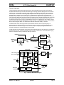
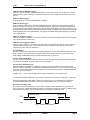
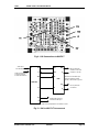
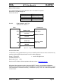
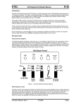
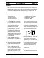
The following block diagram shows the basic sections of the K40 filter board. Audio from the receiver is
amplified and filtered through an initial active filter stage. This stage provides 16dB gain for low level audio
input and also provides some out of band signal rejection. This stage also isolates and protects the SCAF
from the input. The LMC6482 handles large input amplitudes well and clips very cleanly. The first narrow
bandpass filter is made up of two sections of an LTC1068 switched capacitor filter. It provides a filter
bandwidth of about 800Hz with a center frequency of 2210 Hz. The output of the bandpass filter is then fed
into a pair of tone filters made up of the remaining two sections of the LTC1068. These filters are set to 2125
and 2295 Hz respectively. The filtered tones are then fed directly into the PIC processor where they are
rectified, filtered and sliced to produce a digital Baudot serial output. Additionally the PIC provides a signal
gate to squelch output and the LED display if no signal is tuned in. A PWM signal is sent to a second PIC to
drive an LED tuning bar display. The LED bar also indicates mark/space activity on transmit.
In AFSK transmit mode, the PIC generates square waves at either the mark or space frequency as
determined by the FSK input from the K40. The square waves are fed through the bandpass filter which
filters the harmonic content resulting in a clean sine wave output. Frequency change is made at zero
crossing so that there is no phase discontinuity in the signal.
In FSK transmit mode, the K40 KEY output is fed to the transmitter FSK input. The K40 PTT is connected to
the transmitter key input. In other words, KEY controls frequency shift and PTT controls transmitter keying,
with Rx/Tx changeover timing controlled by settings in the K40.
DigiFSK
Mark Filter
2125Hz
1/2 LMC6482
Audio
Input
(AF)
SCAF BPF
4 pole 2210Hz
Input
Bandpass
& Gain
1/2 LTC1068
Mark
Analog
1/4 LTC1068
Space Filter
2295Hz
Space
Analog
1/4 LTC1068
AFSK Buffer
Gain=1
Analog
Gnd
1/2 LMC6482
PIC16F684
Mark Analog
Space Analog
Full
Wav e
Rectify
Low
Pass
IIR
SUM
FO
LED
PWM
Gen
LED
Driver
Tuning
LEDs
PIC12C508
Compare
Thres
hold
IIR LP
20 MHz
Low Pass
Rx/nTx(TR)
TxData(TI)
Tx/Rx
Sw itching
Valid
Signal
Detect
Gate
Rx Out (RO)
DigiFSK
Generate
DigiFSK
Fig 1 – K40 Filter Board Block Diagram
K40FILT User’s Manual
2/20/2007
Page 3