
1
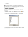
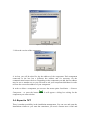
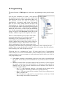
JR eLight
JR Express Light v1.0
User Manual
1. INTRODUCTION .................................................................................................................................. 3
1.1. BUTTONS’ BAR .................................................................................................................................. 4
1.1.1. Buttons related to installations. ................................................................................................ 4
1.1.2. Buttons related to connection ................................................................................................... 4
1.1.3. Others........................................................................................................................................ 5
2. INSTALLATIONS ................................................................................................................................. 6
2.1. CREATING A NEW INSTALLATION ....................................................................................................... 6
2.2. INSTALLATION DATA ......................................................................................................................... 8
2.3. ADDING COMPONENTS ....................................................................................................................... 8
2.4. EXPORT TO TXT ................................................................................................................................ 9
3. PROGRAMMING................................................................................................................................ 11
4. STATE ................................................................................................................................................... 13
4.1. GENERAL ......................................................................................................................................... 13
4.2. OUTPUTS ......................................................................................................................................... 14
4.3. ANALOGICAL ................................................................................................................................... 14
4.4. WIRELESS ........................................................................................................................................ 14
4.5. GRAPHIC STATE............................................................................................................................... 15
4.5.1. Edit mode ................................................................................................................................ 15
4.5.2. Visualization state ................................................................................................................... 17
5. EVENTS ................................................................................................................................................ 19
6. CONNECTIONS .................................................................................................................................. 21
7. KEYPAD ............................................................................................................................................... 23
8. LOG ....................................................................................................................................................... 23
1. Introduction
JR eLight (Express Light) is a software developed for PC communications with central
security panels and its components included in the security installation. Using the
software it’s possible to program the panels and its components. In addition, it’s
possible to receive the state and do a remote control, it means, remote arming and
disarming of the system, zone omission and on. At last, it’s possible to receive the
report events stored in the panel memory and its components.
An installation is a set of components with their respective programs, configurations
and states. The installations can be saved locally in the PC memory as a XML files.
Which this manner it’s possible to open and save installations at any time or using other
PCs as any other typical computer file.
Connecting to central panel can be done using five different systems: Local or direct
connection – using local port or USB adapter -, via analog Modem, using a digital CSD
Modem, by TCP/IP or accessing across a GPRS communicator.
Figure 1 – A global program screenshot.
1.1. Buttons’ bar
Next there is detailed a list of the functions that the user can realize using the buttons.
1.1.1. Buttons related to installations.
Creates a new installation.
Opens an existing installation.
Saves the current installation using the last name.
Saves the current installation with a different name.
Add a new component to the installation.
Removes a component of the installation. Note: The central panel or main device
can’t be removed, only the extra components.
Closes the installation.
1.1.2. Buttons related to connection
Opens some dialog windows asking parameters to configure the connections.
Connects using the current configuration. It needs a type of connection selected
(Local, Modem, CSD, TCP/IP, GPRS) and it must be configured. Otherwise, first will
appear the
dialogs and then it will connect.
Disconnects.
Receives the data of the group or section selected.
Sends the data of the group or section selected.
Sends the Apply instruction to the central panel or the selected component. It
instruction will apply the new configuration.
Verifies values of the programming codes in the group and subgroups selected.
The verification process receives the remote values and compare it with the local ones.
1.1.3. Others
Reset the programming codes with the default values. Note: reset applies to local
values, it means that it will be necessary to send this values in order to change it
remotely.
Shows / hides the KeyPad bar. KeyPad is used to direct program codes like a bus
keypad.
Shows / Hides the log bar.
Quits.
2. Installations
JR eLight is oriented to installations. An installation is a set of components, data and
configurations. An Installation can be saved in XML format and can be opened and
edited by the program at any time. Using this format, the saved files can be copied, sent,
exported etc. independently where the software is installed.
2.1. Creating a new installation
The first step to start using JR eLight is to create a new installations. To do it, follow
these instructions:
1. Select the option Installation->New… in the main menu or click the
the toolbar.
button of
2. You will be asked for the model of the panel you want to add. Select one and press
Ok
Figure 2 – Select model dialog
3. When the selected model has different versions it will appear a dialog box asking for
the model of your device:
Figure 3 – Select version dialog
2.2. Installation data
Once your new installation is created, the first recommended step is to fill the data
section.
Figure 4 – Installation data.
Inside this section the user can set a name to the installation, fill the data of the client
and configure the connections.
Some of the parameters of the connection belong to the installation. For example, the
telephone numbers necessary to call or the remote IP and TCP port depend on the
installation. It’s possible to configure all of this parameters in the data section or using
the
option.
2.3. Adding components
If the installation is not only one central panel and has some other devices like
expansion modules or communicator adapters it will be necessary to add them to the
installation. In order to add a component follow these steps:
1. Select Installation->Add component… in the menu, or press
2. Choose the corresponding model for the component you want to add.
Figure 5 – Choosing model dialog
3. Select the version of the component
Figure 6 – Choosing version dialog
4. At last, you will be asked for the bus address of the component. Each component
connected to the bus has a different bus address and it’s necessary for the
communication between devices. Depending on the component you add, the bus address
may be one or another one so you will need to ask your component distributor in order
to know the correct bus address of your component.
In order to delete a component you can user the menu option Installation -> Remove
Component… or press the button
component you want to delete.
. It will appear a dialog box asking for the
2.4. Export to TXT
There is another possibility in the installation management. You can save and open the
installations whenever you want but sometimes you need a format more visual and
printable than XML. So, JR eLight has the option to export the programming data to a
TXT file. The TXT file will show a tabulated list of all the programming codes of the
central panel and its components. The user will be able to open the TXT file with any
text editor (Word, Notepad, etc.) and print it if it’s necessary.
To export, use the menu option Installation -> Export programming…
3. Programming
The main function of JR eLight is to make easier programming security panels using a
PC.
Once the new installation is created, it will appear in
the installation tree the model of the main device of the
installation and all the other components added to it.
The structure of the tree tries to represent the
installation in a hierarchic mode. Inside each model,
there are one or more folders and one of them is the
Programming one. Inside the Programming folder the
user can find some folders representing different groups
of programming codes or including other subfolders.
When the user selects a folder in the last hierarchic
level all the programming codes that belongs to this
group will appear in the edit panel (main panel of the
window) with their respective description and values.
There are some different types of codes. Some codes
represents options that you can check or uncheck
depending on your configuration. Others are
represented by a grid of selection cells where you can
check or uncheck any of them. Some of the codes are a
textbox that the user has to fill with the correct value
for his configuration. Each code accepts some values
depending on the data which is representing. Consequently, some codes only accept
numbers, other accepts hexadecimal values and other accept strings. Read the manual to
know which type of values accepts each code.
Following, there is a explanation of how to fill some typical types of programming
codes. However, it’s several recommended to read the manual of every central panel or
component that you want to program to really understand which values you need for
each programming code.
•
•
User codes: 4 numbers corresponding to the user code used to arm and disarm
the system. In case that you want to disable the user, fill the text box with value
FFFF.
Phones: Normally filled with phone numbers until 28 characters. If the length of
the number is lower than 28 it will be filled by ‘F’ characters by the program. In
addition, there are some especial characters used to indicate some aspects or
functions explained below:
o One ‘C’ at the beginning indicates to the panel that the phone call is
done using pulses and not by DTMF tones (normal behavior).
o One ‘A’ indicates a pause before continue. Useful when calling across a
PBX or internal calls.
o One ‘D’ indicates to the panel to wait until detects a dial tone. Useful
when calling across PBX or internal calls.
•
•
•
•
Hours: In order to introduce hours for schedules or others you have to enter it in
the format HH:MM. It means, two numbers representing the hour of the day
from 0 to 23, two points ‘:’ separating, and two more numbers indicating the
minutes. The minutes accuracy is usually limited to quarters. It means that if you
enter a value different of 0, 15, 30 or 45 your value will be approximate to the
nearest quarter.
Texts: The text strings use to be limited to 16 characters. The program will fill
with spaces the final characters if your text length is less than 16 characters. The
program doesn’t let you to type more than 16 characters so you may have to
delete the final spaces sometimes when you edit texts.
Times: Use to be a decimal number between 0 and 255.
Reports: Use to be two hexadecimal characters (from ‘0’ to ‘9’ and from ‘a’ to
‘f’) representing some formats and options for report events. More information
in the manual of the device.
The user can reset the codes of a group with the default values using the
reset
button of the toolbar when he is editing it. When the user is selecting a group in the
installation tree, the option applies to the group and all the subgroups inside it.
Consequently, if the user is selecting the Programming group, this option will reset to
the default values all the programming codes of the selected device. The reset option
applies in local so the user may have to send the programming values in order to apply
the changes to the central panel or the component. Read the connection chapter to know
more about transmitting programming values.
4. State
4.1. General
Figure 7 – State panel
General State is a control panel showing all the important information about the state of
the central panel. As seen in the figure 7, in the top left corner is showed the date and
the time of the device. It can be synchronized with the PC time with the first button next
to the date. If the user wants to set the time of the device manually, he can do it using
the second button.
In the first list starting on the left are showed all the zones of the central panel and their
state. Each zone can have five different states: ok, failure, bypassed, detecting and
alarm. Using the buttons just below the zones list the user can bypass a zone or restore
it.
The areas list of the central panel is in the right at the top of the window of the General
State. An area can have two different states, armed and disarmed, and the user can
change it using the buttons just below the list control.
Below the areas zone, there is another list showing the outputs of the device. The list
shows the state of each output (active, inactive) and using the buttons below the list, the
user can change it state.
At last, in the bottom of the state panel the user will be advised with some messages
corresponding with the warning messages of the central panel. There are eight possible
messages:
Pre-fire Alarm.
Inaccurate Date and Time.
No power supply.
Low battery.
Failures.
Entry time.
Exit time.
Alarm memory.
4.2. Outputs
In this section the user can consult the state of the outputs. It’s only informative, so the
user can’t modify it from here.
4.3. Analogical
In this section the user can consult the values of some analogical measures of the central
panel. It shows values like voltage, resistances, temperature, etc.
4.4. Wireless
If the central panel has wireless zones, in this section the user can consult the state of
them.
4.5. Graphic State
In the Graphic State section it’s possible to visualize the state of the zones and outputs
represented by icons in a map. Using the editor, the user can assign a position in the
map for each zone and output. It’s possible too to specify a different type of sensor for
every zone. In addition, it’s possible to have a mosaic of four maps to see all four
simultaneously.
Every time the state is actualized, the maps and images will be actualized too, and it will
show to the user the state (detecting, alarm, failure, etc.) in a very graphical mode.
Figure 8 – Mosaic of maps in the Graphic State
4.5.1. Edit mode
In order to use the Graphic mode JR eLight needs to know which image the user wants
to use as a map. The first step is to select which map the user want to edit and enter in
the edit mode. To enter in the edit mode and add a image as a map follow this steps:
1. Choose the map’s number to edit in the combo box at the top of the graphic state
panel.
2. Press the button “Enter in edit mode”.
3. In the bottom of the panel there is a text box and a button with the caption
“Browse…”. Use the browse button to search the image of your map. The image
must be in GIF format.
Figure 9 – Edit mode
Once the map is added the user can start adding graphic components. There are graphic
components for sensors and for outputs and relays. Use the toolbar in the left of the
panel to add components. The first six icons represents sensors for zones. To add a
sensor in the graphic state follow the next steps:
1. Click the icon in the toolbar of the sensor you want to add.
2. It will appear a window asking for the zone of the central panel assigned to the
sensor. Select one and press Ok.
3. Click in the map in the exact position where you want to put the icon of the
sensor.
4. If you want to change the position of a sensor, drag it to another place. To drag
is keep pressed the left button of the mouse while you move it across the map.
It’s possible to assign the same zone to different sensors. The different sensor that the
user can add are::
Smoke sensor, detects fire.
Water sensor, detects floods.
Infrared sensor, detects intrusions.
Beam sensor, detects intrusions.
Contact sensor, detects doors or windows opening.
Gas sensor, detects gas escapes.
The steps needed to add a new output or relay are very similar to the steps needed to add
a sensor. Follow the steps below:
1. Click the icon in the toolbar of the sensor you want to add.
2. It will appear a window asking for the zone of the central panel assigned to the
sensor. Select one and press Ok.
3. Click in the map in the exact position where you want to put the icon of the
sensor.
4. If you want to change the position of a sensor, drag it to another place. To drag
is keep pressed the left button of the mouse while you move it across the map.
The are three types of outputs in the graphic state:
Horn. Output connected to a horn.
Output. An output connected to anything different of a horn.
Relay.
To delete a component press the icon
want to delete in the map.
and the select the sensor, output or relay you
When all the changes are made the user can exit of the edit mode pressing the button
“Exit of edit mode”. Refresh the state using
.
4.5.2. Visualization state
Outside the edition mode it’s possible to obtain information about the sensors, outputs
and relays pressing the left button of the mouse over the component. Keeping press the
button it will appear a box with information about the component and its state.
Figure 10 – Components state
5. Events
In the events section the user can receive and browse the events stored by the central
panel. It is recommended to download the events of the devices as frequently as
possible because the events memory of the devices is limited.
Figure 11 – Events Panel
There are some different options to list the events in some different ways. First of all,
the user can select which type of events wants to see in the list, filtering the others.
Selecting or unselecting the following checkboxes, the users selects the filters to apply.
The filtering options are:
•
•
•
•
•
•
Show Alarms: list/filter alarms and restores events.
Show Failures: list/filter failures and restores events.
Show ON/OFF: list/filter armings, openings and disarmings and closings
events.
Show Supervisory: list/filter supervisory events.
Show Tests: list/filter tests events.
Show Bypasses: list/filter bypasses events and its restores.
In addition, there is the option of invert the order of the list. The events use to be listed
from the oldest to the newer but sometimes is interesting to see the newest first. In this
case the user can select the invert order checkbox.
Each column of the table shows different information about each event. First, it’s
showed the date and time of the event. The next column corresponds to the contactID
code protocol, which is a very used protocol of alarm events. The column type of event
indicates the type of event and if it is an alarm or a restoration. Every type can be
filtered with the filter options explained before. At last, the column Zone/User indicates
the subject or cause of the event, sometimes a user, sometimes a zone, and sometimes
nobody.
The Export option exports the list to a CSV file. The CSV type of file is importable by
Excel and others spreadsheets like Excel. It is recommended to export the list frequently
and clear the list of JR eLight because, in other case, the list will grow too much and
the installation file will be too large. It may cause some memory and speed problems to
the software.
The Clear button clears the local list of events. It is recommended its use only after
export the events.
At last, there is an option to receive all the events memory. This option will receive all
the memory, so it’s possible that the user receives repeated events downloaded before or
null and erroneous events of the zones not used yet by the central panel. It’s not
recommended to use this option as a normal method to receive the events. To receive
the events normally, it’s recommended to use the
button.
6. Connections
There are five different ways to connect a PC to a central panel using JR eLight
software:
• Local: Using the local LPC-USB connector.
• Modem: Calling using an analogical modem. The modem’s speed is 1200 bps.
• Modem CSD: Calling using a GM29 modem using GSM’s data channel (CSD).
• TCP/IP: LAN or Internet. Only possible when the central panel has the option
and an Internet acces or LAN connection.
• GPRS: Connection TCP/IP with a GPRS communicator. From PC’s point of
view is almost the same as a TCP/IP connection but some details change and it
needs to know if the central panel is connecting to a normal LAN adapter or a
GRPS.
All five types of connection are bidirectional (full duplex).
In order to configure the connections the user can use the button
or fill the form in
the Data section. The program configures automatically all the basic parameters for the
connection like bits per second, bits of data, parity, etc. so the user doesn’t need to
worry about it and he only will have to introduce the parameters really necessary for
every type of connection.
These are the parameters asked by the program depending on the type of connection
selected:
•
Local:
1. Serial (COM) Port where the LPC-USB connector is connected.
•
Módem:
1. Serial (COM) Port where the modem is connected.
2. Phone to call for the bidirectional connection.
3. Use Callback mode Yes/No?
•
Módem CSD:
1. Serial (COM) Port where the modem is connected.
2. Phone to call for the bidirectional CSD connection.
3. Use Callback mode Yes/No?
•
TCP/IP:
1. IP address of the destination.
2. TCP Port of the destination.
•
GPRS:
1. IP address of the destination.
2. TCP Port of the destination.
All of this data (except serial port) are saved with the installation data and are editable
in the data section of the installation. The serial port is saved in the internal
configuration of the software because it doesn’t use to change in the same computer.
However, it can be changed anytime using the option
.
button and wait. The program will
In order to start the connection press the
advise the user when it is connected or will display an error message otherwise.
Once connected, the user can use the following functions:
Disconnects.
Receives the data of the selected group or section.
Sends the data of the selected group or section.
Sends the Apply programming instruction to the selected device.
Verifies the values of the codes inside the selected groups. The verify process
consist in receive the remote values and compare it with the local values.
The function Receive, Send and Verify always apply to the selected section when the
user press the toolbar button. Consequently, when the user is for example in the Events
section and use the option “Receive”, the user will receive the events of the selected
component. In other case, for example, when the user is in a group of the programming
he will receive the values of all the programming codes inside the group.
Because of this behavior, if the user selects a group parent of others groups and uses one
this functions (Receive, Send or Verify), the function will be executed for all the codes
of all the groups inside the parent group. Therefore, to receive, send or verify all
programming, select the folder Programming in the installation tree and use
or
.
,
7. KeyPad
Pressing the button
bar.
of the toolbar appears in the bottom of the window the KayPad
Figure 9 – KeyPad Bar
The user can use the KeyPad Bar to program codes of the central panel or any
component in the bus directly. This is a useful option when the user wants to edit codes
directly using the keypad address of them.
In order to receive the value of a code using the KeyPad bar follow the instructions
below:
1. Type the bus address of the component you want to program (normally the
central panel has the address ‘0’).
2. Type the keypad address of the code to receive.
3. Press the small
near the keypad address textbox.
Once the value is received the user can edit it and send the new value using the small
button
near the value textbox.
8. Log
This application has a log where saves relevant information about executed instructions.
During a normal execution it is not necessary to view the log so it can be hidden.
However, in case of errors in the communication or when the software behavior is not
normal the technical service would use the log to try to find an explanation for the
problems.
Press
to show or hide the Log bar.


![[ENG] CE60-3 GSM Software ComCE v4-2](http://vs1.manualzilla.com/store/data/005829621_1-1503a18c5b086c34f94e34b38a52b968-150x150.png)