1
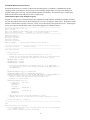
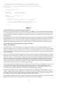
Loop forever, periodically updating the time stamp message object.
The CAN controller will transmit the time stamp message when it receives a
remote frame for it, without any intervention from the CPU. Returns: never
-----------------------------------------------------------------------------*/
void main(void)
{
printf("Program A start\n");
/* Set up */
setup_can();
init_timer();
/* set up CAN interface */
/* initialize timing */
/* Run */
while (1) {
/* infinite loop */
unsigned long t;
t = timer();
update_can_transmit_message(TIME_MO, &t, LEN_CAN_TIME_MSG);
/* Put the processor in idle mode to conserve power.
The next interrupt (from the timer) will wake it up again.
*/
_idle_();
}
}
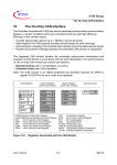
Figure 2
A Brief Description of the C167CR On-chip CAN Interface
The C167CR on-chip CAN interface is an XBUS peripheral. The XBUS is the on-chip manifestation of the external
bus. XBUS peripherals look like external devices to the software and have the same characteristics as external devices.
Since the processor's bit addressing capabilities do not apply to external devices; registers of the CAN module are not
bit-addressable.
The CAN module interfaces to the CPU through several general registers and 15 message objects. Most of the general
registers affect the overall operation of the CAN module and are located from 00’EF00H to 00’EF0FH. Each message
object consists of 15 bytes of registers located from 00’EF10H to 00’EFFEH. Message objects 1 through 14 can be
configured as either transmit or receive objects. Message object 15 is a double-buffered receive-only message object.
Some Unusual Aspects of Programming the On-chip CAN Module:
Message Control Registers
One of the registers in each message object is the message control register. These contain flags which are set and
cleared in a rather unusual way. Each flag is represented by a pair of bits. When the register is read, the value of each
bit pair will be either 01, meaning the flag is clear (i.e. false), or 10, meaning the flag is set (i.e. true). When writing to
the register, these same values may be written to the bit pair to set or clear the flag, or 11 may be written to the bit pair
to leave it unchanged.
There is a good reason for this unusual design. Because the on-chip CAN interface is an XBUS peripheral, it is not bitaddressable. The CPU must access its registers as whole bytes or words. When the CPU needs to change just some of
the bits in a register it can read the register, change the necessary bits, and write the modified value back to the register.
In the case of the message control registers of the message objects, this approach would cause a problem: the CAN
controller may change some of the bits between the time the CPU reads the register and the time the CPU writes the
modified value back. The CAN controller's changes to the register would be lost, even when the bits changed by the
CAN controller are among the bits the CPU was not trying to change.
The example programs in this application note use a collection of preprocessor macros for computing the value to write
to a message control register to set, clear, and leave unchanged any combination of flags. Each of these macros
compiles to a 16-bit unsigned constant in which all but one of the bit pairs is 11. The remaining bit pair is 01 in the
x_CLR macros, or 10 in the x_SET macros. These macros are defined in the file canregs.h.
To change several flags at one time, combine the corresponding macros using the bitwise-AND operator, '&'. For
example, writing CPUUPD_CLR & TXRQ_SET to a message control register simultaneously clears the CPUUPD flag
and sets the TXRQ flag, while leaving the other flags unchanged. Don't combine the x_SET and x_CLR macros for
the same flag, because that would produce the illegal value 00 for that flag's bit pair.
The CPUUPD and MSGLST flags are actually the same bit pair, but the meaning of that bit pair is different depending
on whether the message object is a transmit object (CPUUPD) or a receive object (MSGLST).
3