1
INNOVATIVE TREATMENT SOLUTIONS
•
A 12 mm through hole in the panel board is required.
•
The camera connector is guided through this hole.
•
The camera connector provides the ground connection to the shielding of the MR cabinet.
For temporary use, the camera cable can be brought into the MR cabinet by other means, e.g.
through a service entry hole. In this case, an additional grounding cable should be used to connect
the camera connector to the shield panel grounding.
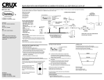
Figure 4: Device and cable configuration
E. Connection of power supply
The power for the camera is transmitted via the camera connector cable. Therefore, the power
supply is connected to the filter box (see figure 5). The required power values are 200 mA, 6-12V.
Video
connector
Power
supply
MR_CAM_12M-Mount_UserManual_v3.sxw
SF - 11/24/05
version: 3
Figure 5: Filter box (rear side)
page 4 of 5
status: approved