1
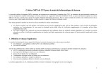
User Manual
PON OLT Series
PON 8510
Headquarters:
No. 25, Alley 15, Lane 120,
Sec. 1. Nei-Hu Rd,
Version: 1.0
Taipei 114, Taiwan
Date: 2007/11/16
TEL: 886-2-26583000
FAX: 886-2-26583232
Beijing Branch:
3F, A Building,
113 Zhi Chun Lu,
HaiDian District,
Beijing, China
Zip Code: 100086
TEL: 86-10-62522081~87
FAX: 86-10-62522077
P/N: 07008-00105
PON 8510 User Manual
Copyright © 2007 TAINET COMMUNICATION SYSTEM CORP.
All right reserved
Notice
This document is protected by the international copyright law. No part of this publication
may be reproduced by any means without the permission of Tainet Communication System
Corporation.
TAINET is a registered trademark, and PON 8510 is trademarks of Tainet Communication
System Corporation.
Other product names mentioned in this manual are used for identification purposes only
and may be trademarks or trademarks of their respective companies.
The information provided from Tainet Communication System Corporation is believed to be
accurate. Any changes and enhancements to the product and to the information thereof will
be documented and issued as a new release to this guide.
Trademark
All products and services mentioned herein are the trademarks, service marks, registered
trademarks or registered service marks of their respective owners.
-i
PON 8510 User Manual
About This Manual
This section guides users on how to use the manual effectively. The manual contains
information needed to install, configure, and operate TAINET’s PON OLT Series. The
summary of this manual is as follows:
Chapter 1:
Overview
Chapter 2:
Specification
Chapter 3:
Basic Operation
Chapter 4:
More Advanced Configuration
Chapter 5:
Maintenance
Chapter 6:
Monitor
Appendix A:
Console PIN Assignment
Appendix B:
Command Line Mode
-ii-
PON 8510 User Manual
Symbols Used in This Manual
3 types of symbols may be used throughout this manual. These symbols are used to advise
the users when a special condition arises, such as a safety or operational hazard, or to
present extra information to the users. These symbols are explained below:
Warning:
This symbol and associated text are used when death or
injury to the user may result if operating instructions are not
followed properly.
Caution:
This symbol and associated text are used when damages to
the equipment or impact to the operation may result if
operating instructions are not followed properly.
Note:
This symbol and associated text are used to provide the
users with extra information that may be helpful when
following the main instructions in this manual.
-iii
PON 8510 User Manual
LIMITED WARRANTY
TAINET’s DISTRIBUTOR shall be responsible to its customers for any and all warranties,
which it makes relating to Products, and for ensuring that replacements and other
adjustments required in connection with the said warranties are satisfactory. TAINET
warrants to DISTRIBUTOR that the Products to be delivered hereunder will be free of
defects in material and workmanship under normal use and service for a period of
twenty-four (24) months [twelve (12) months in Taiwan] following the date of shipment to
DISTRIBUTOR.
If during the warranty period, any component part of the equipment becomes defective by
reason of material or workmanship, and DISTRIBUTOR notifies TAINET of such defect
within seven days after knowing of such defect, TAINET shall, for any Product that TAINET
agrees is defective, at its option, supply a replacement part, request return of equipment to
its plant for repair, or perform necessary repair at the equipment’s location.
At TAINET's
option, DISTRIBUTOR shall destroy any Product that TAINET agrees is defective and shall
provide satisfactory proof of such destruction to TAINET.
TAINET is not responsible for
Products damaged by misuse, neglect, accident or improper installation, or if repairs or
modifications were made by persons other than TAINET’s own authorized service
personnel, unless such repairs by others were made with the written consent of TAINET.
THE ABOVE WARRANTY IS IN LIEU OF ALL OTHER WARRANTIES, EXPRESSED OR
IMPLIED.
THERE ARE NO WARRANTIES THAT EXTEND BEYOND THE FACE
HEREOF, INCLUDING, BUT NOT LIMITED TO, WARRANTIES OF MERCHANTABILITY
AND FITNESS FOR A PARTICULAR PURPOSE, AND IN NO EVENT SHALL TAINET BE
LIABLE FOR CONSEQUENTIAL DAMAGES. If DISTRIBUTOR extends to its customers
any additional warranty with respect to Products that is broader in scope than the warranty
provided by TAINET, DISTRIBUTOR shall be solely responsible for any and all liabilities,
obligations and damages resulting from the extension of such warranty.
-iv-
PON 8510 User Manual
TAINET shall not be liable to any person for any special or indirect damages, including, but
not limited to, lost profits, from any cause whatsoever arising from or in any way connected
with the manufacture, sale, handling, repair, maintenance or use of the Products, and in no
event shall TAINET’s liability exceed the purchase price of the Products.
Software Products are provided “as is” and without warranty of any kind.
TAINET
disclaims all warranties including the implied warranties of merchantability and fitness for a
particular purpose. TAINET shall not be liable for any loss of use, interruption of business
or indirect, special, incidental or consequential damages of any kind. TAINET shall do its
best to provide end users with Software updates during the warranty period under this
Agreement.
TAINET has not been notified of any intellectual property rights or others which may be
infringed by the Products or the promotion, marketing, sale (or resale), or servicing thereof
in the Territory, but TAINET makes NO WARRANTY, EXPRESS OR IMPLIED, WITH
RESPECT THERETO.
-v
PON 8510 User Manual
CONTENT
CHAPTER 1. OVERVIEW ..................................................................................... 1
1.1
OVERVIEW ............................................................................................................................1
CHAPTER 2. SPECIFICATION ............................................................................ 5
2.1
2.2
2.3
2.4
2.5
2.6
PON INTERFACE ...................................................................................................................5
NNI INTERFACE ....................................................................................................................6
MANAGEMENT INTERFACE ....................................................................................................7
CRAFT INTERFACE .................................................................................................................8
FEATURE AND SPECIFICATION ...............................................................................................9
OPERATION ENVIRONMENT .................................................................................................10
2.6.1 Power requirement...................................................................................................................... 10
2.6.2 Temperature ................................................................................................................................ 10
2.6.3 Humidity ..................................................................................................................................... 10
CHAPTER 3. BASIC OPERATION .................................................................... 11
3.1
CONFIGURATION .................................................................................................................12
3.1.1 System......................................................................................................................................... 12
CHAPTER 4. MORE ADVANCED CONFIGURATIONS................................ 15
4.1
CONFIGURATION .................................................................................................................15
4.1.1 OLT ............................................................................................................................................. 15
CHAPTER 5. MAINTENANCE........................................................................... 21
5.1
SYSTEM ...............................................................................................................................21
5.1.1 Firmware Upgrade ...................................................................................................................... 21
5.1.2 Device Maintenance ................................................................................................................... 22
5.1.3 Log.............................................................................................................................................. 22
5.1.4 Save Configuration ..................................................................................................................... 22
5.2
OLT ....................................................................................................................................24
5.2.1 Testing......................................................................................................................................... 24
CHAPTER 6. MONITOR...................................................................................... 27
APPENDIX A CONSOLE PIN ASSIGNMENT .................................................. 29
APPENDIX B COMMAND LINE MODE ........................................................... 31
-vi-
PON 8510 User Manual
FIGURE
FIGURE 1-1 PON NETWORK STRUCTURE ..............................................................................................1
FIGURE 1-2 FRONT PANEL OF OLT DEVICE............................................................................................2
FIGURE 1-3 REAR PANEL OF OLT DEVICE .............................................................................................3
FIGURE 3-1 LOGIN INTERFACE ............................................................................................................ 11
FIGURE 3-2 GENERAL INFORMATION OF SYSTEM.................................................................................12
FIGURE 3-3 CLOCK OF SYSTEM ...........................................................................................................13
FIGURE 3-4 IP ADDRESS OF SYSTEM ....................................................................................................13
FIGURE 3-5 USERS INFORMATION OF SYSTEM .....................................................................................14
FIGURE 4-1 GENERAL INFORMATION OF OLT......................................................................................15
FIGURE 4-2 BRIDGE TABLE .................................................................................................................16
FIGURE 4-3 MULTICASTING MANAGEMENT .........................................................................................16
FIGURE 4-4 PORT STATUS OF OLT MODULE.........................................................................................17
FIGURE 4-5 PVID INFORMATION ........................................................................................................17
FIGURE 4-6 QOS CONFIGURATION OF OLT .........................................................................................19
FIGURE 4-7 TRAFFIC CONFIGURATION OF OLT....................................................................................20
FIGURE 4-8 VLAN CONFIGURATION OF OLT......................................................................................20
FIGURE 5-1 FIRMWARE UPGRADE........................................................................................................21
FIGURE 5-2 DEVICE MAINTENANCE ....................................................................................................22
FIGURE 5-3 SYSTEM LOG FUNCTION ...................................................................................................22
FIGURE 5-4 SAVE CONFIGURATION ......................................................................................................23
FIGURE 5-5 TESTING ...........................................................................................................................24
FIGURE 5-6 ONU SELECTING..............................................................................................................24
FIGURE 5-7 MESSAGE OF TESTING RESULT ..........................................................................................25
T
-vii
PON 8510 User Manual
TABLE
TABLE 1-1 LEDS STATUS INDICATION ...................................................................................................2
TABLE 2-1 PON INTERFACE ..................................................................................................................5
TABLE 2-2 NNI INTERFACE ...................................................................................................................6
TABLE 2-3 MANAGEMENT INTERFACE ..................................................................................................7
TABLE 2-4 CRAFT PORT.........................................................................................................................8
T
TABLE A- 1 RJ-45 TO DB-9 PIN ASSIGNMENT .....................................................................................29
-viii-
Chapter 1 Overview
Chapter 1. Overview
1.1
Overview
“Ethernet Passive Optical Network” (hereafter called “EPON Network”)
comprises an Optical Line Terminal (OLT) system using its individual OLT to
interconnect with one or more specific groups of Optical Network Units (ONUs)
via a corresponding number of Passive Optical Distribution Networks (ODNs) to
construct a broadband point-to-multipoint access network between central office
and customer premises. A Server Provider can provide the broadband triple
play services by way of the EPON Network, such as high-speed Internet access,
VoIP and IPTV services. The PON network diagram is as shown as Figure 1-1.
Figure 1-1 PON network structure
There are two modules can be inserted into the OLT device, each module has
four PON interfaces and four NNI (Gigabit Ethernet) interfaces. The maximum
capacity of OLT device is up to eight NNI interfaces and eight PON interfaces.
-1-
Chapter 1 Overview
The NNI interface of OLT is used to uplink to core network through physical GE
(Gigabit Ethernet) link. One PON interface connects OLT to splitter through an
optical fiber and each splitter can be divided into 16 or 32 optical links each
connected with one ONU. Subscriber’s network can be connected to the UNI
interface of ONU device by physical FE (Fast Ethernet) medium.
On the right side of front panel, there is a MPU module with two management
ports and craft port for OLT as well as ONU devices configuring. Through the
management ports (MGMT 1 or MGMT 2) on the MPU, administrator is able to
configure the device by web interface mode. The pin assignment of craft port is
as Appendix A .
The LEDs of front panel indicate the status as following:
Table 1-1 LEDs status indication
LED
Function
PWR
(green LED)
When OLT power is on,light PWR LED
ALM
(red LED)
When power or fan fail,light ALM LED
NNI (GE) interface *4
GE port for NNI link (1~4 ports)(w/LNK & ACT LED)
Management interface*2
LAN port for management (w/LNK & ACT LED)
PON Link (green LED)*4
Indicating OLT PON port link (1~4 ports)
There is an RST button on each module to reset its configurations to default
values.
PON Interface
Management Port
NNI Interface
Figure 1-2 Front panel of OLT device
-2-
Craft Port
Chapter 1 Overview
AC Power
Fan
DC Power
Figure 1-3 Rear panel of OLT device
The power requirement of OLT device is ether AC or DC.
-3-
Chapter 2 Specification
Chapter 2. Specification
2.1
PON Interface
Table 2-1 PON interface
Item
Transmitter Center wavelength
Parameter
1490nm(1480 to 1500 nm)
Transmitter Spectrum width
Compliant with IEEE 802.3ah
Transmitter Average Launched Power +2~+7 dBm
Receiver Center wavelength
1310nm(1260 to 1360 nm)
Receiver Minimum Sensitivity
-28dBm
Receiver Input Saturation Power
(Overload)
-6.5dBm
Connector type
SC
Data rate
1.25Gbps
Transmission distance
20Km
Transmission method
Single fiber, bi-direction transmission
(2-wavelength WDM)
-5-
Chapter 2 Specification
2.2
NNI Interface
Table 2-2 NNI interface
Item
Supported standards
Parameter
Support auto-negotiation, 1000Base-T Full duplex only
Number of ports
4
Connector
RJ45
Type of cable
Cat.5e , auto MDI/MDI-X
-6-
Chapter 2 Specification
2.3
Management Interface
Table 2-3 Management interface
Item
Supported standards
Parameter
Support auto-negotiation, 10/100 Base-T
Number of ports
2
Connector
RJ45
Type of cable
Cat.5 , auto MDI/MDI-X
-7-
Chapter 2 Specification
2.4
Craft Interface
Table 2-4 Craft port
Item
Supported standards
Parameter
RS232C
Number of ports
1
Baud rate
38400
Connector
RJ45
Type of cable
Need RJ45 to DUB9 adapter
-8-
Chapter 2 Specification
2.5
Feature and Specification
Full compliance to IEEE 802.3ah (Clause 64 and Clause65)
Complete processing and generation of MPCP control messages
Point-to-point emulation between each ONU and OLT using LLID (logical
link identifier)
IEEE 802.1D compliance bridging
Support of up to 8K MAC address learning table
Configurable two QoS mode of operation : 802.1p and DSCP
Traffic profile derived from the service level agreement (SLA) with two
configurable parameters per ONU
Committed Information Rate (CIR)
Peak Information Rate (PIR)
Support of eight priority classes
Strict priority (SP) or weighted round-robin (WRR) or SP+ WRR
scheduling
Intelligent Dynamic Bandwidth Allocation (DBA) algorithms
Per-ONU based upstream traffic policing and downstream traffic shaping
and policing
Support multicast shaping feature to shape specified multicast group
stream
Support ONU remote upgrade
Support IGMP v1/v2 protocol
Support of up to 512 multicast group addresses
In-band management based on Ethernet OAM frames and Ethernet frames
Full compliance with IEEE 802.3ah OAM function
Support per-ONU based OAM loopback
Security management including 802.1x authentication (future)
Support downstream traffic AES or Churning encryption (future)
-9-
Chapter 2 Specification
2.6
Operation Environment
2.6.1
Power requirement
AC: 90~264VAC, 50/60Hz, Input (90W)
DC: -36~-72VDC, Input (92W)
2.6.2
2.6.3
Temperature
Operating
+0℃ ~ +50℃
Storage
-25℃ ~ 75℃
Humidity
Operating
5% ~ 95% non-condensing
Storage
0% ~ 75% non-condensing
-10-
Chapter 3 Basic Operation
Chapter 3. Basic Operation
Administrator can configure the device through web browser by connecting PC to the
Management ports (MGMT1 or MGMT2) of device. The default IP address of device is
192.168.0.1. Administrator can modify the IP address through command line mode or web
configuring mode. Please refer to Appendix B for configuring IP address through command
line mode.
On web configuring mode, the default login user name and password for administrator are:
admin and admin, respectively.
The connection between OLT and ONU device is shown as Figure 1-1.
NOTE: All the OLT and ONU devices must only be configured through the management
port.
Figure 3-1 Login interface
There are three main menu pages on the web interface: Configuration, Maintenance and
Monitor.
-11-
Chapter 3 Basic Operation
3.1
Configuration
3.1.1
System
3.1.1.1
General
For viewing the general information such as: software, hardware and firmware
information, administrator can go to the General submenu.
Figure 3-2 General information of system
3.1.1.2
Clock
To configure or modify the correct time and date of device, administrator can go
to the Clock submenu. Administrator can Key in the correct information and
press Apply button to activate it.
-12-
Chapter 3 Basic Operation
Figure 3-3 Clock of system
3.1.1.3
Host IP
To configure or modify the network IP of device, administrator can go to the
Host IP submenu.
Figure 3-4 IP address of system
-13-
Chapter 3 Basic Operation
3.1.1.4
Users
To change the default user name and password, administrator can go to the
Users submenu. Three roles for different logging levels can be selected. Admin
has not only the highest authority to configure the device but also change other
users’ name as well as password. Operator has the permission as Admin but
not include changing other users’ name and password. User only has the
permission of reading.
Figure 3-5 Users information of system
-14-
Chapter 4 More Advanced Configuration
Chapter 4. More Advanced Configurations
4.1
Configuration
4.1.1
OLT
4.1.1.1
General
This submenu shows the general information of OLT module as Figure 4-1
shown:
Figure 4-1 General information of OLT
4.1.1.2
Bridge
Administrator can select either OLT1 or OLT2 to configure static or dynamic
FDB table. The dynamic FDB learning mode is active after enabling Learning
Enable field and pressing Apply button. Administrator can manual adding one
static destination MAC address, VLAN ID and Egress Port to the FDB table, It
is active after press Add button.
NOTE: the range of Aging Time is 0~1048 seconds. The maximum entry of
Static FDB is 32.
-15-
Chapter 4 More Advanced Configuration
Figure 4-2 Bridge table
4.1.1.3
Multicasting
Administrator can select either OLT1 or OLT2 to configure static or dynamic
Multicast mode (default is dynamic mode). Administrator also can specify one or
more NNI port(s) to enable Multicast traffic on the port(s). The system supports
either IGMPv1 or IGMPv2 (default is IGMPv2).
Administrator can enable the function of multicast traffic shaping by enabling
Action and specifying any desire limit rate. It is active after pressing Apply
button.
Figure 4-3 Multicasting management
-16-
Chapter 4 More Advanced Configuration
4.1.1.4
Port
Administrator can force either NNI or PON port of OLT to be activated or not.
Figure 4-4 Port status of OLT module
4.1.1.5
PVID
To prevent any untagged packet from dropping by OLT, administrator can
manually add VLAN ID to one or more specified NNI port(s). Any VLAN ID can
not be added if it was not specified in the VLAN submenu, in advance. Please
refer to the section 4.1.1.8.
NOTE: The VLAN ID administrator aim to insert must be added to VLAN
submenu in advance and the range of VLAN ID is 1~4094.
Figure 4-5 PVID information
-17-
Chapter 4 More Advanced Configuration
4.1.1.6
QoS
On this submenu, administrator can select the QoS criteria mode, queue
mapping, default CoS queue, default 802.1p value and the scheduling mode of
frame in egress.
Administrator can select one active module to configure it by alternating OLT-1
or OLT-2. Administrator determines the QoS mode by selecting either DSCP or
802.1p mode, and then press the Apply button.
For the QoS Mapping item, administrator can set the DSCP or 802.1p to output
queue mapping table. The three most significant bits of the packet’s DSCP [0:2]
value is used for the mapping (IP precedence) and the allowed range is 0~7.
The greater number it is, the higher priority it has. Administrator can assign each
priority (0 ~ 7) to the same or different queue.
Administrator can set the default 802.1p value to a VLAN tagging packet. The
default value is 0. The default CoS value is used for mapping a packet to an
output queue when QoS mode is 802.1p and the packet is untagged. The value
of CoS can not be set when QoS mode was set to DSCP and the packet was
not recognized as the IP packet. In this scenario, therefore, the value is referred
to the default 802.1p value and its queue mapping.
For selecting the frame egress scheduling mode, there are three modes can be
selected:
Strict Priority: All top priority frames are egress a port until that priority
queue is empty, and then the next lower priority queue frames are sent out.
WRR (Weighted Round Robin): Weights from 1 to 255 can be selected for
each of the 8 queues. The utilization of each queue is scaled to its own
weight value.
Hierarchical mode: queue 7 and 6 are in strict priority and remaining
queues are in WRR mode.
-18-
Chapter 4 More Advanced Configuration
Figure 4-6 QoS configuration of OLT
4.1.1.7
Traffic
Select one OLT entity, enable or disable the Flow Control then press Apply
button to activate or inactivate the Flow Control function. It will generate 802.3x
PAUSE frame on the NNI port after enabling Flow Control.
In DBA mode, there are three items can be selected:
WorkConserv: As long as sufficient bandwidth is available in a cycle and
there are no other contending ONUs , an ONU may get as much bandwidth
as its demand. In other word, the bandwidth allocated to an ONU is not
upper-bounded by its PIR value.
NonWorkConserv: an ONU never get more bandwidth than PIR value
even if there is spare bandwidth available.
CBR: the CIR value is allocated on the each registered ONU even if its
demand for this cycle is less than this value.
-19-
Chapter 4 More Advanced Configuration
Figure 4-7 Traffic configuration of OLT
4.1.1.8
VLAN
Administrator can add one VLAN ID to the specified NNI and/or PON port(s).
The packet with a VLAN ID will be forwarded to the designated port assigned
with the same VLAN ID or it will be drop if OLT didn’t find any matching entries
in the VLAN Table. For example: administrator aim to tag one VLAN ID: 3000 to
any packets through NNI-3 and PON-3 ports. Therefore administrator keys in
3000 on the VLAN ID field and check NNI-3 and PON-3. Finally, press the Add
button to make it available.
NOTE: The maximum entry of VLAN table is 512.
Figure 4-8 VLAN configuration of OLT
-20-
Chapter 5 Maintenance
Chapter 5. Maintenance
The main purpose of this menu is to do system maintenance such as firmware upgrading,
configuration saving, system reboot…etc.
5.1
System
5.1.1
Firmware Upgrade
Please connect the TFTP server to the management port through Ethernet link,
first. To upgrade the firmware of system, administrator has to specify the correct
IP address of TFTP server and the file name of firmware, then, press Apply
button.
Figure 5-1 Firmware upgrade
-21-
Chapter 5 Maintenance
5.1.2
Device Maintenance
Press the Apply button to reboot the system or restore the system to default
value.
Figure 5-2 Device maintenance
5.1.3
Log
This submenu provides system log and download the log to one’s PC. The
system log is recorded when the Log Enable is set to Enable after pressing
Apply button. Press the Download button to download the log information to
administrator’s PC.
Figure 5-3 System log function
5.1.4
Save Configuration
Go to this submenu to save configuration of OLT or ONU if any value was
modified.
-22-
Chapter 5 Maintenance
Figure 5-4 Save configuration
-23-
Chapter 5 Maintenance
5.2
OLT
5.2.1
Testing
Go to the OLT >>Testing submenu to test any ONU unit connected to the OLT
entity.
Figure 5-5 Testing
Press << Select ONU >> button to select one ONU entity, which will be tested.
On the list of ONU units, click one ONU you aim to test (it’s MAC or Name will
be displayed on bold) and return to the OLT Testing submenu. Press Apply
button to see the testing result. Administrator can specify the size and count
number for the testing.
Figure 5-6 ONU selecting
-24-
Chapter 5 Maintenance
The testing result will be shown as following if OLT got response from ONU unit:
Figure 5-7 Message of testing result
-25-
Chapter 6 Monitor
Chapter 6. Monitor
Administrator can view major event logs through the Event Log submenu.
-27-
Appendix A Console Pin Assignment
Appendix A Console Pin Assignment
RJ-45 to DB-9 pin assignment is as following:
Pin Number
1
Description
NC
Note
2
NC
3
RXD
DUB9 pin2 (Output)
4
GND
DUB9 pin5
5
TXD
DUB9 pin3 (Input)
6
NC
7
NC
8
NC
Table A- 1 RJ-45 to DB-9 pin assignment
-29-
Appendix B
Command Line
Appendix B Command Line Mode
Administrator can login to PON 8510 through craft port(Speed:38400, Data bit: 8, Parity: No,
Stop bit: 1, Flow control: No) on the front panel to configure the device. The default user
name is: root and password is: admin.
There are two items can be specified on the command line mode. The first one is to specify
the network configuration. Administrator can specify the network configuration of the device
before entering the mode of web setting interface.
For example:
EPON login: root
Password: *****
=====================
GEPON
=====================
login[54]: root login
on `tty'
1) Modify Network Configuration
2) Show Event Log
3) Restore to default
>1
IP Address (172.16.5.191):192.168.0.118
Netmask (255.255.255.0): 255.255.255.0
-31-
Appendix B Command Line
Default Gateway (172.16.5.254): 192.168.0.1
New system configuration
IP Address: 192.168.0.118
Netmask: 255.255.255.0
Default Gateway: 192.168.0.1
Apply these settings? (Y/N): y
Apply system configuration succeed
Save settings? (Y/N): y
Saving system settings ok.
Bye!
The second item is to show event logs of the device.
1) Modify Network Configuration
2) Show Event Log
>2
n: last n records from now
n=10
Event log total 10 entries:
timestamp
entity
2007-09-28:13:40:04
OLT-2-NNI-3
NNI port up
2007-09-28:13:40:04
OLT-2-NNI-4
NNI port up
2007-09-28:13:40:04
OLT-2-PON-1
type
PON port up
-32-
Appendix B
2007-09-28:13:40:04
OLT-1-NNI-1
NNI port up
2007-09-28:13:40:04
OLT-1-NNI-2
NNI port up
2007-09-28:13:40:04
OLT-1-NNI-3
NNI port up
2007-09-28:13:40:05
OLT-1-NNI-4
NNI port up
2007-09-28:13:40:06
ONU-00:90:bb:14:53:14
On Line
2007-09-28:14:26:15 SYS-FAN-1 Fan fail
2007-09-28:14:26:39 SYS-FAN-1 Fan normal
Bye!
The third item is to restore configuration to default.
1) Modify Network Configuration
2) Show Event Log
3) Restore to default
>3
-33-
Command Line