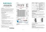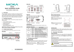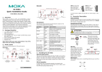
1
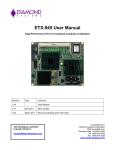
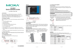
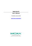
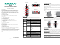
Front View
Power Input
V-
DI x 4
V+
DO x 4
12-48V
1. Overview
4. Installing the W406
COM
DI0
DI1
DI2
DI3
GND
DO0
DO1
DO2
DO3
GSM/GPRS/EDGE
Antenna
W406
Quick Installation Guide
First Edition, April 2009
Top View
Power Input
STEP 1: Insert the top of the DIN-Rail into the slot just below the stiff
metal spring.
LED Indicators
(Ready,Storage)
DIN-Rail Mounting
The aluminum DIN-Rail attachment plate is already attached to the
product casing. When attaching the plate to the W406, make sure that the
stiff metal spring is at the top.
LED Indicators
(Serial Rx/Tx)
Cellular Enable
Bottom View
Signal Strength
The W406 embedded computer has two RS-232/422/485 serial ports,
one 10/100 Mbps Ethernet port, an embedded GSM/GPRS/EDGE
module, an SD socket interface for storage expansion, one USB 2.0
host port, four digital input channels, and four digital output channels.
This combination of features makes the W406 ideal for your wireless
embedded applications.
Serial Port x 2 (RS-232/422/485) Reset Button
Cellular
Reset Button
P1
SD/SIM Card
Socket
P2
Reset to Default
USB 2.0 Host x 1
RS-232/422/485
10/100 Mbps
Ethernet x 1
STEP 2: The DIN-Rail attachment unit will snap into place as shown
below.
metal
spring
metal
spring
Console
Console Port
(RS-232)
2. Package Checklist
DIN-Rail
Before installing the W406, verify that the package contains the
following items:
y 1 W406 embedded computer
y Quick Installation Guide
y Document & Software CD
y Cross-over Ethernet cable: RJ45 to RJ45, 100 cm
y Console port cable: CBL-4PINDB9F-100, 4-pin header to
female DB9 cable
y 1 dBi antenna
y Product Warranty Statement
Optional Accessories
y Wall Mounting Kit
Please notify your sales representative if any of the above items are
missing or damaged.
DIN-Rail
LED Indicators
The following table describes the LED indicators located on the front
panel of the W406.
LED Name
Ready
Storage
GSM/GPRS/
EDGE
LED Color
Green
Off
Green
Off
Green
Off
3. W406 Panel Layout
The W406 comes with two RS-232/422/485 serial ports, one RS-232
console port, one 10/100 Mbps LAN port, an embedded
GSM/GPRS/EDGE module, an SD socket interface for storage expansion,
one USB 2.0 host port, and four digital input channels and four digital
output channels. The following figures show the panel layouts of the
W406.
Signal
Strength
LAN
TxD
P1-P2
RxD
P1-P2
Green
Off
Orange
Green
Off
Green
Off
Yellow
Off
LED Function
Power is on and functioning normally
Power is off or power error exists
SD card is detected
SD card is not detected
ON:
Cellular is ready
Blinking: Conflict with GPRS/EDGE IP,
or DHCP server not responding
GPRS/EDGE is not ready or function error
exists
Number of glowing LEDs indicates signal
strength:
5: Excellent
4: Very good
3: Good
2: Fair
1: Bad
No signal, or GPRS connection failed
10 Mbps Ethernet link
100 Mbps Ethernet link
Disconnected or short circuit
Serial ports P1-P2 transmitting data
Serial ports P1-P2 not transmitting data
Serial ports P1-P2 receiving data
Serial ports P1-P2 not receiving data
P/N: 1802004060010
—1—
—2—
Wall or Cabinet Mounting (optional)
The W406 comes with one metal bracket for attaching it to a wall or the
inside of a cabinet. Using two screws for the bracket, first attach the
bracket to the rear of the W406. Next, use four screws per side to attach
the W406 to a wall or cabinet.
Screws Screws
Screws
5. Connector Description
Power Connector
Connect the 12 to 48 VDC LPS or Class 2 power line to the W406’s
terminal block. If the power is supplied properly, the Power LED will
light up. The OS is ready when the Ready LED glows a solid green.
Grounding the W406
Grounding and wire routing help limit the effects of noise due to
electromagnetic interference (EMI). Run the ground connection from the
ground screw to the grounding surface prior to connecting the power.
ATTENTION
This product is intended to be mounted to a well-grounded mounting
surface, such as a metal panel.
—3—
V+
V-
SG
SG: The Shielded Ground (sometimes called
Protected Ground) contact is the bottom contact of
the 3-pin power terminal block connector when
viewed from the angle shown here. Connect the SG
wire to an appropriate grounded metal surface.
Ethernet Ports
The 10/100 Mbps Ethernet port uses RJ45 connectors.
PIN
Signal
1
ETx+
1
8
2
ETx3
ERx+
6
ERxSerial Ports
The serial ports use DB9 connectors. Each port can be configured by
software for RS-232, RS-422, or RS-485. The pin assignments for the
ports are shown in the following table:
Pin RS-232
1
2
3
4
5
6
7
8
DCD
RxD
TxD
DTR
GND
DSR
RTS
CTS
RS-422
TxDA(-)
TxDB(+)
RxDB(+)
RxDA(-)
GND
-------
RS-485
(4-wire)
TxDA(-)
TxDB(+)
RxDB(+)
RxDA(-)
GND
-------
RS-485
(2-wire)
----DataB(+)
DataA(-)
GND
-------
1 2 3 4 5
6 7 8 9
SD Slot
The W406 has an internal SD slot for storage expansion. The SD slot
allows users to plug in a Secure Digital (SD) memory card compliant
with the SD 1.0 standard for up to 1 GB space, and a Secure Digital High
Capacity (SDHC) memory card compliant with the SD 2.0 standard for
up to 16 GB of additional memory. To install an SD card, first use a
screwdriver to remove the SD slot cover on the front panel to access the
slot. Plug the SD card directly into the socket, and then replace the SD
slot cover.
Console Port
The serial console port, located at the bottom panel is a 4-pin pin-header
RS-232 port. It is designed for serial console terminals, which are useful
for viewing boot-up messages. Use the CBL-4PINDB9F-100 cable
included with the product to connect a PC to the W406’s serial console
port.
USB
The W406 has 1 USB 2.0 full speed host (OHCI) that uses a type A
connector. The port supports keyboard and mouse, and can also be used
—4—
to connect a FlashDisk for storing large amounts of data.
DI, DO
The W406 has an 4-ch digital input and 4-ch digital output. The pinouts
for the I/O are shown in the following figure. For wiring, please refer to
the W406 Hardware User’s Manual for details.
SIM Card Installation
The SIM slot is located on the front panel. Before you install a SIM card,
be sure to shut down the operating system. Use a screwdriver to remove
the protective cover to access SIM card slot. Make sure the chip on the
SIM card is facing up and then plug the SIM card directly into the slot.
Reset to Default
Press the “Reset to Default” button at the bottom panel of the W406 and
hold it in for at least 5 seconds to load the factory default configuration.
After the factory default configuration has been loaded, the system will
reboot automatically. The Ready LED will blink on and off for the first 5
seconds, and then maintain a steady glow once the system has rebooted.
Real-time Clock
The W406’s real-time clock is powered by a lithium battery. We strongly
recommend that you do not replace the lithium battery without help from
a qualified Moxa support engineer. If you need to change the battery,
contact the Moxa RMA service team.
ATTENTION
There is a risk of explosion if the battery is replaced by an incorrect type
of battery.
To use Telnet, you need to know the W406’s IP address and netmask.
However, please note that the W406 uses a DHCP server to acquire an IP
address. You must have a DHCP server within your network. The W406
will acquire an IP address automatically from the DHCP server once it is
connected. For Linux users, use “ifconfig”, for Windows CE users, use
“ipconfig” to know the IP address and the netmask of the W406. Then
you can use telnet to connect to the W406.
Once the W406 is powered on, the Ready LED will light up, and a login
page will open. Use the following default Login name and Password to
proceed. The defaults are:
Login: root
Password: root
8. Configuring the Ethernet Interface
Linux users should follow these steps:
When you power on the computer that has not connected to the local
network or there is no DHCP server available, it will take about 60
seconds for the system to perform the reboot procedure. When it is ready,
use the console port for the first-time configuration of the network
settings with the following command.
#ifdown –a
Disable LAN1 interface (eth0) first, before you reconfigure the LAN
settings.
#vi /etc/network/interfaces
After the boot setting of the LAN interface has been modified, use the
following commands to activate the LAN settings immediately:
#sync ; ifup –a
WinCE 6.0 users should follow these steps:
6. Powering on the W406
To power on the W406, connect the “terminal block to power jack
converter” to the W406’s DC terminal block (located on the top panel),
and then connect the power adaptor. Note that the Shielded Ground wire
should be connected to the bottom pin of the terminal block. It takes
about 30 seconds for the system to boot up. Once the system is ready, the
Ready LED will light up.
7. Connecting the W406 to a PC
Step 1: Go to Start Æ Settings Æ Network and Dial-Up
Connections.You will see two network interfaces.
Step 2: Right-Click the LAN interface to be configured and click
property. A configuration window will pop-up.
Step 3: Click OK after inputting the proper IP address and netmask.
NOTE: Refer to the W406 User’s Manual for other configuration
information.
There are two ways to connect the W406 to a PC: (1) through the serial
console port, or (2) by Telnet over the network. The COM settings for the
serial console port are: Baudrate=115200 bps, Parity=None, Data
bits=8, Stop bits =1, Flow Control=None.
ATTENTION
Use the CBL-4PINDB9F-100 cable included with the product to connect
a PC to the W406’s serial console port. Remember to choose “VT100”
terminal type.
—5—
Click here for online support:
www.moxa.com/support
The Americas:
Europe:
Asia-Pacific:
China:
+1-714-528-6777 (toll-free: 1-888-669-2872)
+49-89-3 70 03 99-0
+886-2-8919-1230
+86-21-5258-9955 (toll-free: 800-820-5036)
© 2009 Moxa Inc. All rights reserved.
Reproduction without permission is prohibited.
—6—